Table of Contents
Advertisement
Available languages
Available languages
Advertisement
Table of Contents

Related Manuals for MSI KA780G Series


Summary of Contents for MSI KA780G Series
- Page 1 KA790GX/ KA780G / KA780V Series MS-7526 (v1.X) Mainboard G52-75511X2...
-
Page 2: Copyright Notice
Alternatively, please try the following help resources for further guidance. Visit the MSI website for FAQ, technical guide, BIOS updates, driver updates, an d ot h er i n f orm at i on: h t t p: / / g l o ba l . -
Page 3: Safety Instructions
Safety Instructions Always read the safety instructions carefully. Keep this User’s Manual for future reference. Keep this equipment away from humidity. Lay this equipment on a reliable flat surface before setting it up. The openings on the enclosure are for air convection hence protects the equip- ment from overheating. -
Page 4: Fcc-B Radio Frequency Interference Statement
FCC-B Radio Frequency Interference Statement T h is eq uip men t h as been tested and found to c omply with the limits for a Class B digital device, pursuant to Part 15 of the FCC Rules. These limits are designed to provide reasonable protection against harmful interference in a residential installation. -
Page 5: Weee (Waste Electrical And Electronic Equipment) Statement
WEEE (Waste Electrical and Electronic Equipment) Statement... -
Page 8: Table Of Contents
CONTENTS Copyright Notice ......................ii Tradema rks ........................ii Revision History ......................ii Technical Support ...................... ii Safety Instructions ....................iii FCC-B Radio Frequency Interference Statement ..........iv WEEE (Waste Electrical and Electronic Equipment) Statement ....... v English ........................En-1 Mainboard Specifications ................. - Page 9 Français ........................Fr-1 Spécifications ..................... Fr-2 Guide rapide des composants ................Fr-4 Processeur : CPU ....................Fr-5 Mémoire ....................... Fr-8 Connecteur d’alimentation ................Fr-10 Panneau arrière ....................Fr-11 Connecteurs ..................... Fr-13 Cavaliers ......................Fr-19 Boutons ......................Fr-20 Interrupteur ....................... Fr-21 Slots ........................
-
Page 10: English
KA790GX/ KA780G/ KA780V Series User’s Guide English En-1... -
Page 11: Mainboard Specifications
Phenom FX/X4/X3/X2, Athlon 64 FX/X2, Sempron in the Socket AM2+/ AM2 package - Supports 4 pin CPU Fan Pin-Header with Fan Speed Control (For the latest information about CPU, please visit http://global.msi.com.tw/index.php?func=cpuform) Hyper Transport Bus - HyperTransport 3.0 supports speed up to 2600 MHz Chipset ®... - Page 12 Connectors Back panel - 1 PS/2 port for mouse or keyboard (auto detection) - 1 VGA port - 1 DVI-D port - 1 Optical S/PDIF-out jack - 1 HDMI port - 6 USB 2.0 ports - 1 ESATA port - 1 LAN jack - 6 flexible audio jacks On-Board Pinheaders/ buttons/ switch - 3 USB 2.0 pinheaders...
-
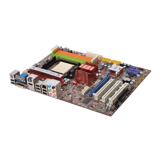
Page 13: Quick Components Guide
M S-7551 M ainboard Quick Components Guide OCSWITCH1, En-21 CPU, SYSFAN2, En-5 En-12 JPWR1, CPUFAN1, En-10 En-15 DDR2, En-8 Back Panel I/O, En-11 SYSFAN1, En-15 JPWR2, En-10 IDE1, En-13 JCI1, En-14 PCI Express POWER1/ RESET1/ slots, En-22 CLR_CMOS1,En-20 SATA1~5, En-14 JTPM1, En-16 PCI Slots, JFP2, En-18... -
Page 14: Central Processing Unit: Cpu
If you do not have the heat sink and cooling fan, contact your dealer to purchase and install them before turning on the computer. For the latest information about CPU, please visit http://global.msi.com.tw/index.php? func=cpuform Important Overheating Overheating will seriously damage the CPU and system. -
Page 15: Cpu Installation For Socket 478
M S-7551 M ainboard CPU Installation Procedures for Socket AM2+/ AM2 1. Please turn off the power and unplug the power cord before Open the lever installing the CPU. Sliding the plate 90 degree 2. Pull the lever s ideways away from the socket. - Page 16 Installing AMD Socket AM2+/AM2 CPU Cooler Set W hen you are installing the CPU, make sure the CPU has a heat sink and a cooling fan attached on the top to prevent overheating. If you do not have the heat sink and cooling fan, contact your dealer to purchase and install them before turning on the computer.
-
Page 17: Memory
M S-7551 M ainboard Memory These DIMM slots are used for installing memory modules. For more information on compatible components, please visit http://global.msi.com. tw/index.php?func=testreport DDR2 240-pin, 1.8V 56x2=112 pin 64x2=128 pin Dual-Channel Memory Population Rules In Dual-Channel mode, the memory modules can transmit and receive data with two data bus lines simultaneously. -
Page 18: Installing Memory Modules
Installing Memory Modules 1. The memory module has only one notch on the center and will only fit in the right orientation. 2. Insert the memory module vertically into the DIMM slot. Then push it in until the golden finger on the memory module is deeply inserted in the DIMM slot. The plastic clip at each side of the DIMM slot will automatically close when the memory module is properly seated. -
Page 19: Power Supply
M S-7551 M ainboard Power Supply ATX 24-Pin Power Connector: JPWR2 This connector allows you to connect an ATX 24-pin power supply. To connect the ATX 24-pin power supply, make sure the plug of the pin 13 power supply is inserted in the proper orientation and the pins are aligned. -
Page 20: Back Panel
Back Panel Mouse / Optical keyboard VGA Port S/PDIF-Out USB Port Line-In RS-Out Line-Out CS-Out HDMI Port SS-Out USB Port DVI-D Port USB Port ESATA Port M ouse/Keyboard ® ® The standard PS/2 mouse/keyboard DIN connector is for a PS/2 mouse/keyboard. - Page 21 M S-7551 M ainboard The standard RJ-45 LAN jack is for connection to Yellow Green / Orange the Local Area Network (LAN). You can connect a network cable to it. Color LED State Condition LAN link is not established. Left Yellow On (steady state) LAN link is established.
-
Page 22: Connectors
Connectors Floppy Disk Drive Connector: FDD1 This connector supports 360KB, 720KB, 1.2MB, 1.44MB or 2.88MB floppy disk drive. FDD1 IDE Connector: IDE1 This connector supports IDE hard disk drives, optical disk drives and other IDE devices. IDE1 Important If you install two IDE devices on the same cable, you must configure the drives separately to master / slave mode by setting jumpers. - Page 23 M S-7551 M ainboard Serial ATA Connector: SATA1~5 This connector is a high-speed Serial ATA interface port. Each connector can con- nect to one Serial ATA device. SATA1 SATA3 SATA5 SATA2 SATA4 Important Please do not fold the Serial ATA cable into 90-degree angle. Otherwise, data loss may occur during transmission.
- Page 24 Fan Power Connectors: CPUFAN1, SYSFAN1, SYSFAN2 The fan power connectors support system cooling fan with +12V. W hen connecting the wire to the connectors, always note that the red wire is the positive and should be connected to the +12V; the black wire is Ground and should be connected to GND. If the mainboard has a System Hardware Monitor chipset on-board, you must use a specially designed fan with speed sensor to take advantage of the CPU fan control.
- Page 25 M S-7551 M ainboard Front Panel Audio Connector: JAUD1 This connector allows you to connect the front panel audio and is compliant with ® Intel Front Panel I/O Connectivity Design Guide. JAUD1 Pin Definition SIGNAL DESCRIPTION AUD_MIC Front panel microphone input signal AUD_GND Ground used by analog audio circuits AUD_MIC_BIAS...
- Page 26 Front USB Connector: JUSB1 / JUSB2 / JUSB3 ® This connector, compliant with Intel I/O Connectivity Design Guide, is ideal for con- necting high-speed USB interface peripherals such as USB HDD, digital cameras, M P3 players, printers, modems and the like. Pin Definition SIGNAL SIGNAL...
- Page 27 M S-7551 M ainboard Front Panel Connectors: JFP1, JFP2 These connectors are for electrical connection to the front panel switches and LEDs. ® The JFP1 is compliant with Intel Front Panel I/O Connectivity Design Guide. JFP1 Pin Definition SIGNAL DESCRIPTION Power Power HD_LED +...
-
Page 28: Jumpers
Jumper Clear CMOS Jumper: JBAT1 There is a CMOS RAM onboard that has a power supply from an external battery to keep the data of system configuration. W ith the CMOS RAM, the system can auto- matically boot OS every time it is turned on. If you want to clear the system configuration, set the jumper to clear data. -
Page 29: Buttons
M S-7551 M ainboard Buttons The motherboard provides the following buttons(optinoal) for you to set the computer’s function. This section will explain how to change your motherboard’s function through the use of button. Power Button: POWER1 (optional) This power button is used to turn-on or turn-off the system. Press the button to turn- on or turn-off the system. -
Page 30: Switch
Switch This mainboard provides the following switch for you to set the computer’s function. This section will explain how to change your mainboard’s function through the use of s witch. Overclock FSB Switch: OCSWITCH1 You can overclock the FSB to increase the processor frequency by changing the switch. -
Page 31: Slots
M S-7551 M ainboard Slots PCI (Peripheral Component Interconnect) Express Slot The PCI Express slot supports the PCI Express interface expansion card. The PCI Express 2.0 x16 supports up to 8.0 GB/s transfer rate. The PCI Express x1 supports up to 250 MB/s transfer rate. PCI Express x16 Slot PCI Express x 1 Slot Important... - Page 32 1. Select the Advanced View from the view drop menu. 2. From the Graphics Settings tree in the Catalyst Control Center, click CrossFire 3. From the Graphics Adapter list, select the graphics card that acts as the Display GPU. 4. Select Enable CrossFire 5.
-
Page 33: Pci Interrupt Request Routing
M S-7551 M ainboard PCI (Peripheral Component Interconnect) Slot The PCI slot supports LAN card, SCSI card, USB card, and other add-on cards that comply with PCI specifications. 32-bit PCI Slot PCI Interrupt Request Routing The IRQ, acronym of interrupt request line and pronounced I-R-Q, are hardware lines over which devices can send interrupt signals to the microprocessor. -
Page 34: Bios Setup
BIOS Setup This chapter provides basic information on the BIOS Setup program and allows you to configure the system for optimum use. You may need to run the Setup program when: * An error message appears on the screen during the system booting up, and requests you to run BIOS SETUP. - Page 35 M S-7551 M ainboard Entering Setup Power on the computer and the system will start POST (Power On Self Test) process. W hen the message below appears on the screen, press <DEL> key to enter Setup. Press DEL to enter SETUP If the message disappears before you respond and you still wish to enter Setup, restart the system by turning it OFF and On or pressing the RESET button.
- Page 36 The M ain Menu ® ® Once you enter AMI or AWARD BIOS CMOS Setup Utility, the Main Menu will appear on the screen. The Main Menu allows you to select from ten setup functions and two exit choices. Use arrow keys to select among the items and press <Enter> to accept or enter the sub-menu.
- Page 37 Select [Ok] and press Enter to save the configurations and exit BIOS Setup utility. Important The configuration above are for general use only. If you need the detailed settings of BIOS, please see the manual in English version on MSI website. En-28...
- Page 38 4. Cell Menu Introduction : This menu is for advanced user who want to overclock the mainboard. Important Change these settings only if you are familiar with the chipset. Current CPU/ DRAM Frequency These items show the current clocks of CPU and Memory frequency. Read-only. AMD Cool’n’Quiet The Cool’n’...
- Page 39 M S-7551 M ainboard Important To ensure that Cool’n’Quiet function is ac- tivated and will be working properly, it is required to double confirm that: 1. Run BIOS Setup, and select Cell Menu. U n d e r C e l l M e n u , f i n d A M D Cool’n’Q uiet, and s et this item to “Enable.”...
- Page 40 FSB/DRAM Ratio This item will allow you to adjust the FSB/Ratio of the memory. Adjusted DRAM Frequency (MHz) It shows the adjusted DRAM frequency. Read-only.. HT Link Speed This item allows you to set the Hyper-Transport Link speed. Setting to [Auto], the system will detect the HT link speed automatically.
-
Page 41: Software Information
Utility menu - The Utility menu shows the software applications that the mainboard supports. W ebSite menu- The W ebSite menu shows the necessary websites. Important Please visit the MSI website to get the latest drivers and BIOS for better system performance. En-32... -
Page 42: Deutsch
KA790GX/ KA780G/ KA780V Series Benutzerhandbuch Deutsch De-1... -
Page 43: Spezifikationen
Speicher - DDR2 1066/800/667/533 SDRAM (240Pin/ 1.8V) - 4 DDR2 DIMMs (max. 8GB) (W eitere Informationen zu kom patiblen Speicherm odulen finden Sie unter http://global.msi.com.tw/index.php?func=testreport) - Unterstützt die 10/100/1000 Fast Ethernet über Realtek 8111C Audio ® - Onboard Soundchip Realtek ALC888 - Flexible 8-Kanal Audio-Ausgang mit “Jack Sensing”... - Page 44 RAID - SATA1~5 unterstützen die Modi RAID 0/ 1/ 0+1/ 5 Anschlüsse Hintere Ein-/ und Ausgänge - 1 PS/2 Anschluss für Maus oder Tastatur (automatische Detektion) - 1 VGA Anschluss - 1 DVI-D Anschluss - 1 optische S/PDIF-Ausgang - 1 HDMI Anschluss - 6 USB 2.0 Anschlüsse - 1 ESATA Anschluss - 1 LAN Anschluss...
-
Page 45: Komponenten-Übersicht
M S-7551 M ainboard Komponenten-Übersicht OCSWITCH1, De-21 CPU, SYSFAN2, De-5 De-12 JPWR1, CPUFAN1, De-10 De-15 DDR2, De-8 Back Panel I/O, De-11 SYSFAN1, De-15 JPWR2, De-10 IDE1, De-13 JCI1, De-14 PCI Express POWER1/ RESET1/ slots, De-22 CLR_CMOS1,De-20 SATA1~5, De-14 JTPM1, De-16 PCI Slots, JFP2, De-18 De-24... -
Page 46: Cpu (Central Processing Unit
Sie sich bitte mit Ihrem Händler in Verbindung, um einen solchen zu erwerben und danach zu installieren, bevor Sie Ihren Computer anschalten. Um die neuesten Informationen zu unterstützten Prozessoren zu erhalten, besuchen Sie bitte http://global.msi.com.tw/index.php?func=cpuform Wichtig Überhitzung Überhitzung beschädigt die CPU und das System nachhaltig, stellen Sie stets ei ne korrekt e Funkti onsweis e des CP U Kühlers si cher, um di e CPU v or... - Page 47 M S-7551 M ainboard Vorgehensweise beim CPU Einbau beim Sockel AM2+/ AM2 1. Bitte Schalten Sie das System aus und ziehen Sie den Netz- Open the lever stecker, bevor Sie die CPU einbauen. Sliding the plate 90 degree 2. Ziehen Sie den Hebel leicht seitlich weg vom Sockel, heben Sie ihn danach bis zu einem Winkel von ca.
- Page 48 Installation des AMD Sockel AM2+/AM2 CPU Kühlersets W enn Sie die CPU einbauen, stellen Sie bitte sicher, dass Sie auf der CPU einen Kühlkörper mit aktiven Prozessorlüfter anbringen, um Überhitzung zu vermeiden. Verfügen Sie über keinen aktiven Prozessorlüfter mit Kühlkörper, setzen Sie sich bitte mit Ihrem Händler in Verbindung, um einen solchen zu erwerben und zu installieren, bevor Sie Ihren Computer anschalten.
-
Page 49: Speicher
M S-7551 M ainboard Speicher Diese DIMM-Steckplätze nehmen Arbeitsspeichermodule auf. Die neusten Informationen über kompatible Bauteile finden Sie unter http://global.msi. com.tw/index.php?func=testreport DDR2 240-polig, 1.8V 56x2=112 Pole 64x2=128 Pole Populationsregeln für Dual-Channel-Speicher Im Dual -Chan nel-M odus könn en Ar beit s s pei c herm odul e Dat en üb er z wei Datenbusleitungen gleichzeitig senden und empfangen. - Page 50 Installieren der Arbeitsspeichermodule 1. Das Arbeitsspeichermodul hat nur eine Kerbe in der Mitte und passt nur in eine Richtung in den Steckplatz. 2. Stecken Sie das Arbeitsspeichermodul senkrecht in den DIMM-Steckplatz ein. Drüc ken Sie ansc hließend das Arbeits speichermodul nach unten, bis die Kontaktseite richtig tief in dem DIMM-Steckplatz sitzt.
-
Page 51: Stromversorgung
M S-7551 M ainboard Stromversorgung ATX 24-poliger Stromanschluss: JPWR2 Mit diesem Anschluss verbinden Sie den ATX 24-poligen Anschluss des Netzteils. Achten Sie bei dem Verbinden des ATX 24-poligen pin 13 Stromanschlusses darauf, dass der Anschluss des Netzteils richtig auf den Anschluss an der Hauptplatine ausgerichtet ist. Drücken Sie dann den Anschluss des Netzteils fest nach unten, um eine richtige Verbindung zu gewährleisten. -
Page 52: Rücktafel
Rücktafel Maus / Optical Tastatur VGA Port S/PDIF-Out USB Port Line-In RS-Out Line-Out CS-Out HDMI Port SS-Out USB Port DVI-D Port USB Port ESATA Port Maus/Tastatur ® Die Standard PS/2 Maus/Tastatur Stecker Mini DIN ist für eine PS/2® Maus/Tastatur. VGA Anschluss Die DB 15-Pin Buchse dient zum Anschluss eines VGA Monitors. - Page 53 M S-7551 M ainboard Die Standard RJ-45 Buchse ist für Anschlus zum Gelb Grün / Orange an ein Lokales Netzwerk (Local Area Network - LAN). Hier kann ein Netzwerkkabel angeschlossen werden. Farbe LED Status Zustand Keine Verbindung mit dem LAN. Links Orange An (Dauerleuchten)
-
Page 54: Anschlüsse
Anschlüsse Anschluss des Diskettenlaufwerks: FDD1 Diese Anschluss unterstützt ein Diskettenlaufwerke mit 360KB, 720KB, 1.2MB, 1. 44MB oder 2.88MB Kapazität. FDD1 IDE Anschluss: IDE1 An diesen Anschluss können IDE Festplatten, optische Laufwerke und andere Geräte betrieben werden. IDE1 Wichtig Verbinden Sie zwei Laufwerke über ein Kabel, müssen Sie das zweite Laufwerk im Slave-Modus konfigurieren, indem Sie entsprechend den Jumper setzen. - Page 55 M S-7551 M ainboard Serial ATA Anschluss: SATA1~5 Der Anschluss ist eine Hochgeschwindigkeits Schnittstelle der Serial ATA. Anschluss kann ein S-ATA Gerät angeschlossen werden. SATA1 SATA3 SATA5 SATA2 SATA4 Wichtig Bitte falten Sie das Serial ATA Kabel nicht in einem Winkel von 90 Grad, da dies zu Datenverlusten während der Datenübertragung führt.
- Page 56 Stromanschlüsse für Lüfter: CPUFAN1, SYSFAN1, SYSFAN2 Die Anschlüsseunterstützen aktive Systemlüfter mit + 12V. CPU FAN kann Smart FAN Funktion unterstützen. Wenn Sie den Anschluss herstellen, sollten Sie immer darauf achten, dass der rote Draht der positive Pol ist, und mit +12V verbunden werden sollte, der schwarze Draht ist der Erdkontakt und sollte mit GND verbunden werden.
- Page 57 M S-7551 M ainboard Audioanschluss des Frontpanels: JAUD1 Dieser Anschluss ermöglicht den Anschluss von Audioein- und -ausgängen eines Frontpanels. Der Anschluss entspricht den Richtlinien des “ Intel ® Front Panel I/O Connectivity Design Guide”. JAUD1 Polzuweisung SIGNAL BESCHREIBUNG MIC_L Mikrofon - linker Kanal Erde MIC_R Mikrofon - rechter Kanal...
- Page 58 USB Vorderanschluss: JUSB1 / JUSB2 / JUSB3 ® Dieser Anschluss entspricht den Richtlinien des Intel I/O Connectivity Design Guide, ist bestens geeignet, Hochgeschwindigkeits- USB- Peripheriegeräte anzuschließen, wie z.B. USB Festplattenlaufwerke, Digitalkameras, M P3-Player, Drucker, M odems und ähnliches. Polzuweisung SIGNAL SIGNAL JUSB1/2/3 USB0-...
- Page 59 M S-7551 M ainboard Frontpanel Aanschlüsse: JFP1, JFP2 Diese Anschlüsse sind für das Frontpanel dienen zum Anschluss der Schalter und LEDs des Frontpaneels. JFP1 erfüllt die Anforderungen des “Intel Front Panel I/O Connectivity Design Guide“. JFP1 Polzuweisung SIGNAL BESCHREIBUNG Power Power Switch HD_LED +...
-
Page 60: Jumpers
Jumpers CMOS leeren-Jumper: JBAT1 Auf der Hauptplatine befindet sich ein CMOS RAM, das von einer zusätzlichen Batterie mit Strom versorgt wird, um die Systemkonfigurationsdaten zu behalten. Mit den Daten im CMOS RAM kann das System automatisch das Betriebssystem hochfahren, wann immer das System eingeschaltet wird. Wenn Sie die Systemkonfiguration löschen möchten, dann stellen Sie bitte den Jumper so ein, dass die Daten gelöscht werden. -
Page 61: Tasten
M S-7551 M ainboard Tasten Das Motherboard unterstützt die die folgenden Tasten (optinoal), um die Funktion des Computers einzustellen. Dieser Abschnitt beschreibt, wie man die Funktionen des Motherboards durch den Gebrauch der Taste ändert. Ein-/Aus-Schalter: POWER1 (optional) Dieser Ein-/ Aus-Schalter verwendet, um das System ein- und auszuschalten. Drücken Sie diese Taste, um das System ein- bzw. -
Page 62: Schalter
Schalter Die Hauptplatine stellt den folgenden Schalter für Sie zur Verfügung, um die Funktion des Computers einzustellen. Dieser Abschnitt erklärt, wie man Funktion der Hauptplatine durch den Gebrauch von Schalter ändert. Übertaktung FSB Steckbrücke: OCSWITCH1 Übertaken der FSB, um die Prozessorfrequenz erhöhen durch das Andern die Steckbrücke. -
Page 63: Steckplätze
M S-7551 M ainboard Steckplätze PCI (Peripheral Component Interconnect) Express-Steckplatz Der PCI Express-Steckplatz unterstützt eine Erweiterungskarte mit der PCI Express- Schnittstelle. Der PCI Express 2.0x 16-Steckplatz unterstützt eine Transferrate von bis zu 8.0 GB/ Der PCI Express x1-Steckplatz unterstützt eine Transferrate von bis zu 250 MB/s. PCI Express x16 Steckplatz PCI Express x1 Steckplatz Wichtig... - Page 64 1. W ählen Sie die vorgerückte Ansicht vom Ansichtaufklappmenü vor. 2. Vom Grafik-Einstellungen im Catalyst Control Center, klicken CrossFire 3. Von der Grafikadapter-Liste, wählen Sie die Grafikkarte aus, die als die Anzeige GPU dient. 4. W ählen Sie “Enable CrossFire TM”...
- Page 65 M S-7551 M ainboard PCI (Peripheral Component Interconnect)-Steckplatz Der PCI-Steckplatz kann LAN-Karten, SCSI-Karten, USB-Karten und sonstige Zusatzkarten aufnehmen, die mit den PCI-Spezifikationen konform sind. 32-Bit PCI Steckplatz PCI-Unterbrechungsanforderungs-Routing Eine IRQ (Interrupt Reques t; Unterbrec hungs anf orderung)-Leitung is t eine Hardwareleitung, über die ein Gerät Unterbrechungssignale zu dem Mikroprozessor schicken kann.
-
Page 66: Bios Setup
BIOS Setup Dieses Kapitel enthält Informationen über das BIOS Setup und ermöglicht es Ihnen, Ihr System optimal auf Ihre Anforderungen einzustellen. Notwendigkeit zum Aufruf des BIOS besteht, wenn: * W ährend des Bootvorgangs des Systems eine Fehlermeldung erscheint und Sie zum Aufruf des BIOS SETUP aufgefordert werden. - Page 67 M S-7551 M ainboard Aufruf des BIOS Setups Nach dem Einschalten beginnt der Computer den POST (Power On Self Test - Selbstüberprüfung nach Anschalten). Sobald die Meldung unten erscheint, drücken Sie die Taste <Entf>(<Del>) um das Setup aufzurufen. Press DEL to enter SETUP W enn die Nachricht verschwindet, bevor Sie reagieren und Sie möchten immer noch ins Setup, starten Sie das System neu, indem Sie es erst AUS- und danach wieder ANSCHALTEN, oder die “RESET”-Taste am Gehäuse betätigen.
- Page 68 Das Hauptmenü ® ® Nachdem Sie das AMI oder AWARD BIOS CMOS Setup Utility, aufgerufen haben, erscheint das Hauptmenü. Es weist zehn Setup- Funktionen und zwei Arten das Menü zu verlassen auf. Verwenden Sie die Pfeiltasten, um im Menü zu navigieren und drücken Sie die Eingabetaste (<Enter>), um ein Untermenü...
- Page 69 Drücken Sie auf [OK] und <Enter>, um die (neuen) Einstellungen zu speichern und das BIOS Setup zu verlassen. Wichtig Die Konfiguration oben dienen nur generellen Zwecken. Wenn Sie detaillierte BIO S- Einstellungen benötigen, dann sehen Sie bitte das Handbuch in Englischer Sprache auf der MSI Website ein. De-28...
- Page 70 4. Cell Menu Introduction : Das Menü ist für den weiteren Benutzer, der die Hauptplatine übertakten mögen. Wichtig Nur wenn Sie mit dem Chipsatz vertraut sind, können Sie die Einstellung ändern . Current CPU / DRAM Frequency Zeigt die derzeitige Frequenz der CPU/ Speicher. Nur Anzeige. AMD Cool’n’Quiet Die Cool’n’...
- Page 71 M S-7551 M ainboard Wichtig Für eine einwandfreie Funk tion v on Cool’n’Quiet muss folgende Vorgehens- weise unbedingt sichergestellt werden: 1. BIOS Setup ausführen und Cell Menu auswählen. Under Cell M enu setzen Sie AM D Cool’n’Quiet auf [Enabled]. 2. Öffnen Sie Windows und wählen Sie [Start]->...
- Page 72 FSB/DRAM Ratio Können Sie hier den FSB/Ratio des Speichers anpassen. Adjusted DRAM Frequency (MHz) Gibt der verstellt Frequenz des DDR Speicher. Nur Anzeige. HT Link Speed Gibt die maximale Betriebsfrequenz des Taktgebers des Hypertransport Links vor. Mit der Einstellung [Auto],erkennt das System die HT Link Geschwindigkeit automatisch.
-
Page 73: Software-Information
Gebrauchsmenmenü - das Gebrauchsmenü zeigt die SoftwareAnwendungen das die mainboard Unterstützungen. W ebSite Menü - das W ebsite Menü zeigt die notwendigen W ebsite. Wichtig Besichtigen Sie bitte die MSI Website, um die neuesten Treiber und BIOS für bessere System Leistung zu erhalten. De-32... -
Page 74: Français
KA790GX/ KA780G/ KA780V Séries Guide d’utilisation Français Fr-1... -
Page 75: Spécifications
M émoire supportée - DDR2 1066/800/667/533 SDRAM (240pin/ 1.8V) - 4 DDR2 DIMMs (8GB Max) (Pour plus d’informations sur les com posants com patibles, veuillez visiter http://global.msi.com.tw/index.php?func=testreport) - Supporte 10/100/1000 Fast Ethernet par Realtek 8111C Audio ® - Puce intégrée par Realtek ALC888 - 8-canaux audio flexibles avec détection de jack... - Page 76 Connecteurs Panneau arrière - 1 port PS/2 pour une souris ou un clavier (auto détection) - 1 port VGA - 1 port DVI-D - 1 jack S/PDIF-out optique - 1 port HDMI - 6 ports USB 2.0 - 1 port ESATA - 1 jack LAN - 6 jacks audio flexibles Connecteurs/ boutons/ interrupteurs intégrés...
-
Page 77: Guide Rapide Des Composants
Carte mère M S-7551 Guide rapide des composants OCSWITCH1, Fr-21 CPU, SYSFAN2, Fr-5 Fr-12 JPWR1, CPUFAN1, Fr-10 Fr-15 DDR2, Fr-8 Panneau arrière SYSFAN1, Fr-15 I/O, Fr-11 JPWR2, Fr-10 IDE1, Fr-13 JCI1, Fr-14 Slot PCI POWER1/ RESET1/ Express, Fr-22 CLR_CMOS1,Fr-20 SATA1~5, Fr-14 JTPM1, Fr-16 Slots PCI, JFP2, Fr-18... -
Page 78: Processeur : Cpu
équipée d’un ventilateur de refroidissement attaché sur le dessus pour éviter la surchauffe. Si vous n’en avez pas, contactez votre revendeur pour en acheter et installez les avant d’allumer votre ordinateur. Pour plus d’informations sur le CPU, veuillez visiter http://global.msi.com.tw/index. php?func=cpuform Important Surchauffe La surchauffe endommage sérieusement l’unité... - Page 79 Carte mère M S-7551 Procédure d’installation de CPU pour Socket AM2+/ AM2 1. Veuillez éteindre l’alimentation et en débrocher le cordon T i r e z l e Open the lever avant d’installer le CPU. l e v i e r B o u g e z Sliding l e pl at ea u...
- Page 80 Installation du ventilateur du CPU de AMD Socket AM2+/AM2 Quand vous installez votre CPU, assurez-vous que le CPU possède un système de refroidissement pour prévenir les surchauffes. Si vous n’en avez pas, contactez votre revendeur pour vous en procurer un et installer le avant d’allumer l’ordinateur.
-
Page 81: Mémoire
Carte mère M S-7551 Mémoire Ces slots DIMM servent à installer les modules de mémoire. Pour plus d’informations sur les composants compatibles, veuillez visiter http://global. msi.com.tw/index.php?func=testreport DDR2 240-pin, 1.8V 56x2=112 pin 64x2=128 pin Règles de population des mémoire à canaux-doules En mode de Canal double, les modules de mémoire peuvent transmettre et recevoir... - Page 82 Installation des modules mémoire 1. Le module de mémoire possède une seule encoche en son centre et ne s’adaptera que s’il est orienté de la manière convenable. 2. Insérez le module de mémoire à la verticale dans le slot du DIMM. Poussez-le ensuite jusqu’à...
-
Page 83: Connecteur D'alimentation
Carte mère M S-7551 Connecteur d’alimentation Connecteur d’alimentation ATX 24-Pin : JPWR2 Ce connecteur vous permet de connecter l’alimentation ATX 24-pin. Pour cela, assurez-vous que la pris e d’alimentation est bien pin 13 positionnée dans le bon sens et que les goupilles soient alignées. Enfoncez alors la prise dans le connecteur. -
Page 84: Panneau Arrière
Panneau arrière Souris / S/PDIF-Out Clavier Port VGA optique Port USB Line-In RS-Out Line-Out CS-Out Port HDMI SS-Out Port USB Port DVI-D Port USB Port ESATA Souris/Clavier ® Le standard connecteur de souris/clavier DIN de PS/2 est pour une souris ou un ®... - Page 85 Carte mère M S-7551 La prise standard RJ-45 LAN sert à la connexion Jaune Vert / Orange au réseau local (Local Area Network (LAN)). Vous pouvez y relier un câble de réseau. Couleur LED Statut Condition La connexion au réseau LAN n’est pas établie. Eteinte La connexion au réseau LAN est établie.
-
Page 86: Connecteurs
Connecteurs Connecteur Floppy Disk Drive : FDD1 Ce connecteur supporte le lecteur de disquette de 360KB, 720KB, 1.2MB, 1.44MB ou 2.88MB. FDD1 Connecteur IDE : IDE1 Ce connecteur supporte les lecteurs de disque dur IDE, lecteurs optiques de disque et d’autre périphériques IDE. IDE1 Important Si vous installez deux périphériques IDE sur le même câble, vous devez configurer... - Page 87 Carte mère M S-7551 Connecteur Sérial ATA : SATA1~5 Ce connecteur est un port d’interface de série ATA haut débit. Chaque connecteur peut être relié à un appareil de série ATA. SATA1 SATA3 SATA5 SATA2 SATA4 Important Veuillez ne pas plier le câble de série ATA à 90°. Autrement des pertes de données pourraient se produire pendant la transmission.
- Page 88 Connecteur d’alimentation du ventilateur : CPUFAN1, SYSFAN1, SYSFAN2 Les connecteurs de courant du ventilateur supportent le ventilateur de refroidissement du système avec +12V. Lors du branchement des fils aux connecteurs, faites toujours en sorte que le fil rouge soit le fil positif devant être relié au connecteur +12V; et que le fil noir soit le fil de mise à...
- Page 89 Carte mère M S-7551 Connecteur audio panneau avant : JAUD1 Ce connecteur vous permet de connecter un audio sur le panneau avant. Il est conforme au guide de conception de la connectivité Entrée/sortie du panneau avant Intel ® . JAUD1 Définition de pins SIGNAL DESCRIPTION...
- Page 90 Connecteur USB avant : JUSB1 / JUSB2 / JUSB3 Ce connecteur est conforme au guide de conception de la connectivité Entrée/sortie ® , il est idéal pour relier les périphériques d’interface USB à du panneau avant Intel haut débit tels les disques durs externes, les appareils photo numériques, les lecteurs M P3, les imprimantes, les modems et les appareils similaires.
- Page 91 Carte mère M S-7551 Connecteurs du panneau avant : JFP1, JFP2 Ces connecteurs sont fournis pour la connecxion électrique aux interrupteus et LEDs du panneau avant. Le JFP1 est conforme au guide de conception de la connectivité Entrée/sortie du panneau avant Intel ® . Définition des pins pour JFP1 SIGNAL DESCRIPTION...
-
Page 92: Cavaliers
Cavaliers Cavalier d’effacement du CMOS : JBAT1 Il y a un CMOS RAM intégré, qui possède un bloc d’alimentation alimenté par une batterie externe, destiné à conserver les données de configuration du système. Avec le CMOS RAM, le système peut lancer automatiquement le système d’exploitation chaque fois qu’il est allumé. -
Page 93: Boutons
Carte mère M S-7551 Boutons Cette carte mère fournit des boutons (optinonel), qui servent à régler la fonction de l’ordinateur. Cette partie vous explique comment changer la fonction de carte mère par l’utilisation de ces boutons. Bouton d’alimentation : POWER1 (optionnel) Le bouton d’alimentation sert à... -
Page 94: Interrupteur
Interrupteur Cette carte mère fournit un interrupteur comme suivant, qui sert à régler la fonction de l’ordinateur. Cette partie vous explique comment changer la fonction de carte mère par l’utilisation de l’interrupteur. Interrupteur du FSB d’overclocking : OCSWITCH1 Vous pouvez overclocker le FSB afin d’augmenter la fréquence du processeur en changeant l’interrupteur. -
Page 95: Slots
Carte mère M S-7551 Slots Slot PCI (Peripheral Component Interconnect) Express Le slot PCI Express supporte la carte d’expension de l’interface du PCI Express. Le slot PCI Express 2.0x 16 supporte un taux de transfert jusqu’à 8.0 GB/s. Le slot PCI Express x1 supporte un taux de transfert jusqu’à 250 MB/s. Slot PCI Express x16 Slot PCI Express x 1 Important... - Page 96 1. Choisissez cet Advanced View dans le menu de navigation View. 2. De l’arbre de réglages graphiques dans le Catalyst Control Center, cliquez CrossFire 3. Du liste Graphics Adapter, choisissez la carte graphique qui fonctionne comme un Display GPU. 4. Choisissez Enable CrossFire 5.
- Page 97 Carte mère M S-7551 Slot PCI (Peripheral Component Interconnect) Le slot PCI supporte la carte LAN, la carte SCSI, la carte USB et d’autres cartes ajoutées qui sont compatibles avec les spécifications de PCI. Slot 32-bit PCI Chemins de revendication d’interruption de PCI IRQ est l’abréviation de “interrupt request line”.
-
Page 98: Réglages Bios
Réglages BIOS Ce chapitre donne des informations concernant le programme de réglage de BIOS et vous permet de configurer le système pour obtenir des performances d’utilisation optimum. Vous aurez peut-être besoin de lancer le programme de réglage quand : * Un message d’erreur apparaît sur l’écran pendant le démarrage du système, qui vous demande de lancer SETUP (Réglage). - Page 99 Carte mère M S-7551 Réglages d’Entrée Allumez l'ordinateur et le système lancera le processus POST (Test automatique d'allumage). Lorsque le message ci-dessous apparaît à l'écran, appuyez sur la tou- che <DEL> pour entrer dans les réglages. Appuez sur DEL pour entrer dans SETUP (Réglages) Si le message disparaît avant que vous ne répondiez et que vous souhaitez encore entrer dans Setup (Réglages), redémarrez le système en OFF (éteignant) puis en On (rallumant) en appuyant sur le bouton RESET (Réinitialiser).
- Page 100 M enu principal ® ® Une fois entré dans l’unité de réglages AMI ou AWARD BIOS CMOS, le Menu princi- pal appaît sur l’écran. Le Menu Principal vous permet de sélectionner de dix foncions de réglage et deux choix de sortie. Utilisez les touches de flèche pour sélectionner parmi les objets et appuyez sur <Enter>...
- Page 101 Choisir [Ok] et appuyer sur Enter afin de sauvegarder les configurations et l’unité de réglages de quitter BIOS. Important Les configurations précédantes ne sont que pour l’utilisation générale. Si vous avez besoin de réglages détaillés du BIOS, veuillez vous référer au manuel de l’édition anglaise sur la page d’internet de MSI. Fr-28...
- Page 102 4. Cell Menu Introduction (Introduction du Menu cell) : Ce menu est pour des utilisations avancée destinée à overclocker la carte mère. Important Ne changez pas ces réglages sauf que vous connaissiez bien ces chipsets. Current CPU/ DRAM Frequency (Fréquence actuelle du CPU/ DRAM) Ces articles montrent les horloges actuelles de la fréquence du CPU ou de la mémoire.
- Page 103 Carte mère M S-7551 Important Afin d’assurer que la fonction Cool’n’Quiet est activée et qu’elle marchera correctment il est nécessaire de confirmer doublement que : 1. Fonc tionnez les réglages du BIO S, c ho is is s e z C el l M e nu . So us C el l M enu, trouv ez AM D Cool’n’Q uiet, mettez celui-là...
- Page 104 FSB/DRAM Ratio (Ratio FSB/ DRAM) Cet article vous permet d’ajuster le FSB/Ratio de la mémoire. Adjusted DRAM Frequency (MHz) (Fréquence ajustée du DRAM ) Il montre la fréquence ajustée du DRAM. Lecture uniquement. HT Link Speed (Vitesse de HT Link) Cet article pour permet de régrler la vitesse du Hyper-Transport Link.
-
Page 105: Information De Logiciel
Menu de services – Il m ontre les applications logicielles supportées par la carte mère. Menu du site W eb – Il vous indique les sites webs utiles Important Veuillez consulter le site Web de MSI pour obtenir les derniers pilotes et BIOS pour améliorer l’exécution du système de votre ordinateur. Fr-32... -
Page 106: Русский
Серия KA790GX/ KA780G/ KA780V Руководство пользователя Русский Ru-1... -
Page 107: Характеристики
SB700/ SB750 Память - DDR2 1066/800/667/533 SDRAM (240конт/ 1.8V) - 4 слота DDR2 DIMM (8GB Max) (За дополнительной информацией о совместимых компонентах посетите сайт http://global.msi.com.tw/index.php?func=testreport) - Поддержка 10/100/1000 Fast Ethernet на чипсете Realtek 8111C Аудио - Интегрированный чипсет Realtek ®... - Page 108 Коннекторы Задней панели - 1 PS/2 порт для мыши или клавиатуры (авто детектирование) - 1 порт VGA - 1 порт DVI-D - 1 разъем Optical S/PDIF-out - 1 порт HDMI port - 6 порта USB 2.0 - 1 порт ESATA - 1 разъем...
-
Page 109: Руководство По Размещению Компонентов
MS-7551 Системная плата Руководство по размещению компонентов OCSWITCH1, Ru-21 CPU, SYSFAN2, Ru-5 Ru-12 JPWR1, CPUFAN1, Ru-10 Ru-15 DDR2, Ru-8 Back Panel I/O, Ru-11 SYSFAN1, Ru-15 JPWR2, Ru-10 IDE1, Ru-13 JCI1, Ru-14 PCI Express POWER1/ RESET1/ slots, Ru-22 CLR_CMOS1,Ru-20 SATA1~5, Ru-14 JTPM1, Ru-16 PCI Slots, JFP2, Ru-18... -
Page 110: Cpu (Центральный Процессор
п е ре г р ев а пр о ц ес с о ра п ри е го р аб о те о б яз а тел ь н о у с та н о ви те процессорный кулер. Если у вас нет процессорного кулера, пожалуйста, свяжитесь с дилером с цель ю приобретения и его ус тановки до того, как включите компьютер. Самую последнюю информацию о CPU можно получить на сайте http://global.msi. com .tw/index.php?func=cpuform Внимание Перегрев... - Page 111 MS-7551 Системная плата Установка CPU в Socket AM2+/ AM2 1. Перед установкой CPU, пожалуйста, отключите Open the lever питание и выньте вилку блока питания из розетки. Sliding the plate 90 degree 2. Поднимите в вертикальное положение рычажок, находящийся сбоку розъема. 3.
- Page 112 Установка вентилятора процессора AM2+/AM2 в AMD Socket Во из бежание пе регрева пр и его рабо те обязате льно у стан овите вентилятор процессора. Ес ли у вас нет процес с орного вентилятора, пожалуйста, свяжитесь с дилером с целью приобретения и его установки до того, как...
-
Page 113: Память
MS-7551 Системная плата Память Эти слоты DIMM используются для установки модулей памяти. За дополнительной информацией о совместимых компонентах посетите сайт http://global.msi.com.tw/index.php?func=testreport DDR2 240-pin, 1.8V 56x2=112 pin 64x2=128 pin Правила установки модулей памяти для работы в двухканальном режиме В двухканальном режимемодули памяти могут передавать и принимать данные... - Page 114 Установка модулей памяти 1. Модули памяти имеют только одну прорезь в середине. Модуль войдет в разъем только при правильной ориентации. 2. Вставьте модуль в DIMM слот в вертикальном направлении. Затем нажмите на него, чтобы золоченые контакты глубоко погрузились в DIMM слот. Если модуль...
-
Page 115: Разъем Питания
MS-7551 Системная плата Разъем питания 24-контактный разъем питания ATX: JPWR2 Этот разъем позволяет подключить 24-контактный питания ATX. Для подключения источника убедитесь, что его разъем и pin 13 контакты правильно сориентированы. Затем плотно вставьте его в разъем на системной плате. Вы также можете исполь зовать 20-контактный AT X блок п... -
Page 116: Задняя Панель
Задняя панель Mouse / Optical keyboard VGA Port S/PDIF-Out USB Port Line-In RS-Out Line-Out CS-Out HDMI Port SS-Out USB Port DVI-D Port USB Port ESATA Port Разъемы мыши/клавиатуры Стандартные разъемы DIN PS/2 для подключения мыши/клавиатуры с ® интерфейсом PS/2 ® Порт... - Page 117 MS-7551 Системная плата Разъем LAN Стандартный разъем RJ-45 для подключения к Жёлт. Зелен./ Оранж. локальной вычислительной сети (LAN). К нему подключается кабель локальной сети. Цвет Состояние LED Описание Нет LAN соединение не установлено. Лев. Жёлт . Есть (постоянно) LAN соединение установлено. Есть...
-
Page 118: Коннекторы
Коннекторы Разъем FDD: FDD1 Разъем поддерживает FDD ёмкостью 360KB, 720KB, 1.2MB, 1.44MB или 2.88MB. FDD1 Разъем IDE: IDE1 Разъем поддерживает жёсткий диск IDE, дополнительное дисковое устройство и другие устройства с интерфейсом IDE. IDE1 Внимание При подключении двух устройств на одном кабеле, следует установить устройства... - Page 119 MS-7551 Системная плата Разъем Serial ATA: SATA1~5 Данный разъем является высокоскоростным портом интерфейса Serial ATA. Любой разъем Serial ATA может соединяться с одним устройством Serial ATA. SATA1 SATA3 SATA5 SATA2 SATA4 Внимание Избегайте, пожалуйста, резких изгибов кабеля Serial ATA. В противном случае...
- Page 120 Разъемы питания вентиляторов: CPUFAN1, SYSFAN1, SYSFAN2 Разъемы питания вентиляторов поддерживают вентиляторы с питанием +12В. При подключении необходимо помнить, что красный провод подключается к шине +12В, черный - к земле GND. Если на системной плате установлена микросхема аппаратного мониторинга, необходимо использовать специальные вентиляторы с...
- Page 121 MS-7551 Системная плата Выносной разъем аудио: JAUD1 Этот коннектор позволяет подключить выносной разъем аудио на передней панели и соответствует руководству Intel ® Front Panel I/O Connectivity Design. JAUD1 Pin Definition SIGNAL DESCRIPTION AUD_MIC Front panel microphone input signal AUD_GND Ground used by analog audio circuits AUD_MIC_BIAS Microphone power AUD_VCC...
- Page 122 Разъем USB передней панели: JUSB1 / JUSB2 / JUSB3 Разъем, соответствует спецификации Intel ® I/O Connectivity Design, идеально подходит для подключения таких высокоскоростных периферийных устройств, как USB HDD, цифровые камеры, MP3 плееры, принтеры, модемы и им подобные. Pin Definition SIGNAL SIGNAL JUSB1/2/3 USB0-...
- Page 123 MS-7551 Системная плата Коннекторы передней панели: JFP1, JFP2 Эти коннекторы ис поль зуются для подключения кнопок и индикаторов, расположенных на передней панели корпуса. Коннектор JFP1 соответствует руководству Intel ® Front Panel I/O Connectivity Design. JFP1 Pin Definition SIGNAL DESCRIPTION Power Power HD_LED + Hard disk LED pull-up...
-
Page 124: Перемычки
Перемычки Перемычка очистки CMOS: JBAT1 На плате установлена CMOS память с питанием от батарейки, хранящая данные о конфигурации системы. С помощью памяти CMOS, система автоматически загрузится каждый раз при включении. Если у вас возникает необходимость сбросить конфигурацию системы (очистить CMOS), вос пользуйтесь этой перемычкой. -
Page 125: Кнопки
MS-7551 Системная плата Кнопки На этой системной плате имеются дополнительные кнопки (опционально) для ус т ан ов к и фун к ц и й к ом п ь ю т ер а. Э т а г л ав а п оя с н я е т в оз м ож н ос т и использования... -
Page 126: Переключатели
Переключатели Н а э той с ис т ем ной п л ат е и мею тс я д оп олн ит ель н ые п ерек лю чат ел и (опциональ но) для установки функций компьютера. Эта глава поясняет возможности... -
Page 127: Слоты
MS-7551 Системная плата Слоты Слот PCI (Peripheral Component Interconnect) Express Слот PCI Express поддерживает карты расширения интерфейса PCI Express. Слот PCI Express 2.0x 16 поддерживает скорость передачи данных до 8.0 ГБ/с. Слот PCI Express x1 поддерживает скорость передачи данных до 250 МБ/с. Слот... - Page 128 1. Выберите Advanced View из меню View. 2. Из Graphics Settings в Catalyst Control Center, выберите CrossFire 3. Из списка Graphics Adapter, выберите видеокарту, которая будет выводить изображение. 4. Выберите Enable CrossFire 5. Нажмите Apply. При включении Hybrid Cros s FireX , функция...
- Page 129 MS-7551 Системная плата Слот PCI (Peripheral Component Interconnect) Слот PCI позволяет установить карты LAN, SCSI, USB и другие дополнительные карты расширения, которые соответствуют спецификации PCI. 32-bit слот PCI Маршрутизация запросов прерывания PCI IRQ - сокращение от interrupt reques t (line) - линия запроса прерывания, аппаратная...
-
Page 130: Настройка Bios
Настройка BIOS В этой главе приводятся основные сведения о режиме настройки BIOS (BIOS SETUP), который позволяет установить оптимальную конфигурацию системы. Этот режим может потребоваться в следующих случаях: * Во время загрузки системы появляется сообщение об ошибке с требованием запустить BIOS SETUP. * Вы... - Page 131 MS-7551 Системная плата Вход в режим настройки Включите питание компьютера. При этом запустится процедура POST (Тест включения питания). Когда на экране появится приведенное ниже сообщение, нажмите клавишу <DEL> для входа в режим настройки. Press DEL to enter SETUP Если с ообщение ис чезло, а вы не успели нажать клавишу, перезапустите систему, выключив...
- Page 132 The Main M enu (Главное меню) При входе в режим настройки BIOS от AMI ® или AWARD ® на экране отображается Главное меню. Главное меню позволяет выбрать десять функций настройки и имеет два варианта выхода. Для перемещения по пунктам используются клавиши...
- Page 133 Setup и нажмите <Enter>, появится следующее сообщение: Нажмите [Ok], чтобы сохранить конфигурацию и выйти из BIOS Setup. Внимание Приведенная выше конфигурация подходит для общего применения. Если же вам требуются более тонкие настройки BIOS, обратитесь к английской версии руководства на веб-сайте MSI. Ru-28...
- Page 134 4. Cell M enu Introduction : Это меню позволяет управлять тактовыми частотами при разгоне. Внимание Вам можно заменять эти устройства только при вашем знакомстве с чипсетом. Current CPU/ DRAM Frequency Эти пункты показывают текущие частоты CPU и памяти. Только для чтения. AMD Cool’n’Quiet Технология...
- Page 135 MS-7551 Системная плата Внимание Ч т о б ы у б е д и т ь с я в т о м , ч т о тех нол огия Cool’n’Q uiet вк лючена и работает правильно, необходимо: 1. Зайти в программ у BIOS Setup, и в...
- Page 136 FSB/DRAM Ratio Этот пункт позволяет регулировать коэффициент между FSB и памятью. Adjusted DRAM Frequency (МГц) Этот пункт показывает текущую частоту DRAM. Только для чтения. HT Link Speed Этот пункт позволяет установить скорость передачи по шине Hyper-Transport. При установке в [Auto], система автоматически определяет скорость HT. Auto Disable DRAM /PCI Frequency При...
-
Page 137: Сведения О Программном Обеспечении
активации устройства. Utility menu (Меню утилит) - Содержит прикладные программы для поддержки системной платы. W ebSite menu (Меню вебсайтов) - Содержит список необходимых вебсайтов. Внимание Если же вам требуются более тонкие настройки BIOS, обратитесь к руководству на веб-сайте MSI. Ru-32...
Need help?
Do you have a question about the KA780G Series and is the answer not in the manual?
Questions and answers