Table of Contents
Advertisement
Advertisement
Table of Contents

Related Manuals for MSI K8N Diamond Plus Series


Summary of Contents for MSI K8N Diamond Plus Series
- Page 1 K8N Diamond Plus Series MS-7220 (v1.X) ATX Mainboard G52-M7220X3...
- Page 2 FCC-B Radio Frequency Interference Statement This equipment has been tested and found to comply with the limits for a class B digital device, pursuant to part 15 of the FCC rules. These limits are designed to provide reasonable protection against harmful interference in a residential installation. This equipment generates, uses and can radiate radio frequency energy and, if not installed and used in accordance with the instruction manual, may cause harmful interference to radio communications.
-
Page 3: Copyright Notice
Copyright Notice T he material in this document is the intellec tual property of M ICRO-STAR INTERNATIONAL. W e take every care in the preparation of this document, but no guarantee is given as to the correctness of its contents. Our products are under continual improvement and we reserve the right to make changes without notice. -
Page 4: Technical Support
Alternatively, please try the following help resources for further guidance. † Visit the MSI homepage & FAQ site for technical guide, BIOS updates, driver updates, and other information: http://www.msi.com.tw & http://www.msi. -
Page 5: Weee Statement
WEEE Statement... -
Page 8: Table Of Contents
CONTENTS FCC-B Radio Frequency Interference Statement............ii Copyright Notice.......................iii Revision History.......................iii Technical Support....................iv Safety Instructions....................iv WEEE Statement......................v English......................E-1-1 Getting Started.....................E-1-3 Hardware Setup...................E-2-1 BIOS Setup....................E-3-1 Français.......................F-1 Manuel d’utilisation...................F-3 Deutsch.......................G-1 Benutzerhandbuch..................G-3 viii... -
Page 9: English
Getting Started K8N Diamond Plus Series User’s Manual English E1-1... - Page 10 M S-7220 ATX M ainboard E1-2...
-
Page 11: Getting Started
C51D & nForce™4 SLI chipsets for optimal sys- ® tem efficiency. Designed to fit the advanced AMD K8 Athlon 64 FX / Athlon 64X2/ Athlon 64 processor, the K8N Diamond Plus Se- ries mainboard delivers a high performance and professional desk- top platform solution. E1-3... -
Page 12: Mainboard Specifications
† Supports 1 PCI Express x4 slot interface supports PCI Express x2 transfer rate (supports PCI Express Bus specification v1.0a compliant) † Two 32-bit 3.3V/5V Master PCI Bus slots, includes one orange slot which supports 2 master for MSI special PCI function card (ex. wireless LAN and bluetooth combo card.). On-Board IDE †... - Page 13 Getting Started On-Board SATA † nForce 4 SLI supports 4 SATA-II ports (SATA1-4). Transfer speed is up to 3 Gb/ s. Supports RAID 0/ 1/ 0+1/ RAID 5 or JBOD mode. † Silicon Image’s SATARAID supports another 2 SATA-II ports (SATA5/6). Transfer rate is up to 3 Gb/s.
- Page 14 † ATX Form Factor (30.4 cm X 24.4 cm) M ounting † 9 mounting holes MSI Reminds You... To create a bootable RAID volume for a Windows 2000 environment, Microsoft’s Windows 2000 Service Pack 4 (SP4) is required. As the...
-
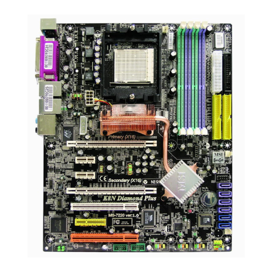
Page 15: Mainboard Layout
P CI _ E4 JCD1 JLPC1 PCI 1 CREATIVE VT6306 CA0106-DAT (Optional) Silicon Image P CI _ E5 RAID JFP2 (Optional) SYSFAN1 (Optional) (Optional) PCI 2 JUSB1 JUSB2 JUSB3 JFP1 JAUD1 J1394_1 J1394_2 K8N Diamond Plus (MS-7220 v1.X) Series ATX Mainboard E1-7... -
Page 16: Packing Contents
M S-7220 ATX M ainboard Packing Contents SATA RAID Driver MSI Driver/ Creative Audio Driver/ Utility CD Diskette MSI motherboard SATA Cable/ D-Bracket 2 SLI Video Link Card Power Cable (Optional) (Optional) Round Cable of Round Cable of 1394 Cable... -
Page 17: Hardware Setup
Hardware Setup Chapter 2. Hardware Setup Hardware Setup This chapter tells you how to install the CPU, memory modules, and expansion cards, as well as how to setup the jumpers on the mainboard. Also, it provides the instructions on connecting the periph- eral devices, such as the mouse, keyboard, etc. -
Page 18: Quick Components Guide
M S-7220 ATX M ainboard Quick Components Guide CPU, p.2-3 JPWR2, p.2-9 DDR DIMMs, p.2-6 CPUFAN1, S_FAN1, JCI1, p.2-20 JPWR3, p.2-9 p.2-15 p.2-15 JIR1, p.2-18 FDD1, p.2-15 Back Panel I/O, p.2-11 JPWR1, p.2-9 PCI_E1, p.2-25 IDE1/2, p.2-16 PWRFAN1, p.2-15 PCI_E2, p.2-25 JV1, p.2-24 PCI_E3, p.2-25 JDB1, p.2-21... - Page 19 If you do not have the heat sink and cooling fan, contact your dealer to purchase and install them before turning on the computer. For the latest information about CPU, please visit http://www.msi.com.tw/pro- gram/products/mainboard/mbd/pro_mbd_cpu_support.php. MSI Reminds You...
-
Page 20: Cpu Installation Procedures For Socket 939
M S-7220 ATX M ainboard CPU Installation Procedures for Socket 939 1. Please turn off the power and unplug the power cord before Open Lever installing the CPU. Sliding 2. Pull the lever s ideways away 90 degree Plate from the socket. Make sure to raise the lever up to a 90-de- gree angle. - Page 21 MSI Reminds You... Mainboard photos shown in this section are for demonstration of the cooler installation for Socket 939 CPUs only. The appearance of your mainboard may vary depending on the model you purchase.
-
Page 22: Introduction To Ddr Sdram
The mainboard provides 4 slots for 184-pin DDR SDRAM DIMM (Double In-Line Memory Module) modules and supports the memory size up to 4GB. You can install DDR266/333/400 modules on the DDR DIMM slots (DIMM1~4). For the updated supporting memory modules, please visit http://www.msi.com.tw/ program/products/mainboard/mbd/pro_mbd_trp_list.php. DIMM1~4 (from left to right) Channel A (DIMM1 &... -
Page 23: Recommended Memory Combination List
128MB~1GB 128MB~1GB 128MB~1GB 512MB~4GB MSI Reminds You... - Dual-channel DDR works ONLY in the 3 combinations listed in the table shown in the previous page. - Please select the identical memory modules to install on the dual channel, and DO NOT install three memory modules on three DIMMs, or it may cause some failure. -
Page 24: Installing Ddr Modules
3. The plastic clip at each side of the DIMM slot will automatically close. Notch Volt MSI Reminds You... You can barely see the golden finger if the module is properly in- serted in the socket. E2-8... -
Page 25: Power Supply
+12V JPWR2 JPWR3 MSI Reminds You... 1. These three connectors connect to the ATX power supply and have to work together to ensure stable operation of the mainboard. 2. Power supply of 450 watts (and above) is highly recommended for system stability. -
Page 26: Important Notification About Power Issue
M S-7220 ATX M ainboard Important Notification about Power Issue NForce chipset is very sensitive to ESD (Electrostatic Discharge), therefore this issue mostly happens while the users intensively swap memory modules under S5 (power-off) states, and the power code is plugged while installing modules. Due to several pins are very sensitive to ESD, so this kind of memory-replacement actions might cause system chipset unable to boot. -
Page 27: Back Panel
Hardware Setup Back Panel The back panel provides the following connectors: L-In RS-Out Parallel M ou se 1394 Port USB Ports SPDIF L-Out CS-Out Keyboard COM Port (Optional) SPDIF Out (Coaxial) (Optical) Mouse Connector (Green) / Keyboard Connector (Purple) ® The mainboard provides a standard PS/2 mouse/keyboard mini DIN connector ®... -
Page 28: Serial Port Connector
M S-7220 ATX M ainboard Serial Port Connector The mainboard offers one 9-pin male DIN connector as the serial port. The port is a 16550A high speed communication port that sends/receives 16 bytes FIFOs. You can attach a serial mouse or other serial devices directly to the connector. Pin Definition 1 2 3 4 5 SIGNAL... -
Page 29: Audio Port Connectors
Hardware Setup LAN (RJ-45) Jack The mainboard provides 2 standard RJ-45 jacks for connection to single Local Area Network (LAN). This Giga-bit LAN enables data to be transferred at 1000, 100 or 10Mbps. You can connect a network cable to either LAN jack. Giga-bit LAN Pin Definition SIGNAL DESCRIPTION... - Page 30 M S-7220 ATX M ainboard Parallel Port Connector: LPT1 The mainboard provides a 25-pin female centronic connector as LPT. A parallel port is a standard printer port that supports Enhanced Parallel Port (EPP) and Ex- tended Capabilities Parallel Port (ECP) mode. Pin Definition SIGNAL DESCRIPTION...
-
Page 31: Fan Power Connectors
SYSFAN1 PW RFAN1 NBF AN1 MSI Reminds You... 1. Always consult the vendors for proper CPU cooling fan. 2. CPUFAN1 supports fan control. You can install Core Center util- ity that will automatically control the CPU fan speed according to the actual CPU temperature. - Page 32 IDE2 (Secondary IDE Connector) IDE2 can also connect a Master and a Slave drive. MSI Reminds You... If you install two hard disks on cable, you must configure the second drive to Slave mode by setting its jumper. Refer to the hard disk documentation supplied by hard disk vendors for jumper setting instructions.
- Page 33 Take out the dust cover and connect to the hard disk devices Connect to serial ATA ports MSI Reminds You... Please do not fold the serial ATA cable in a 90-degree angle, which will cause the loss of data during the transmission. E2-17...
-
Page 34: Front Usb Connectors: Jusb1/Jusb2/Jusb3
M S-7220 ATX M ainboard Front Panel Connectors: JFP1 / JFP2 The mainboard provides two front panel connectors for electrical connection ® to the front panel switches and LEDs. JFP1 is compliant with Intel Front Panel I/O Connectivity Design Guide. JFP1 Pin Definition SIGNAL DESCRIPTION... -
Page 35: Front Panel Audio Connector
Hardware Setup MSI Reminds You... Note that the pins of VCC and GND must be connected correctly, or itmay cause some damage. Front Panel Audio Connector: JAUD1 The JAUD1 front panel audio connector allows you to connect to the front ®... - Page 36 M S-7220 ATX M ainboard IEEE 1394 Connectors: J1394_1 / J1394_2 (optional) The mainboard provides two 1394 pin headers that allow you to connect IEEE 1394 ports via an external IEEE1394 bracket. Pin Definition SIGNAL SIGNAL TPA+ TPA- Ground Ground J1394_1/ J1394_2 TPB+ TPB-...
-
Page 37: D-Bracket 2 Connector
Hardware Setup D-Bracket™ 2 Connector: JDB1 The mainboard comes with a JDB1 connector for you to connect to D-Bracket™ 2. D-Bracket™ 2 is a USB Bracket that supports both USB1.1 & 2.0 spec. It integrates four LEDs and allows users to identify system problem through 16 various combina- tions of LED signals. - Page 38 M S-7220 ATX M ainboard G reen Description D-Bracket™ 2 System Power ON The D-LED will hang here if the processor is damaged or not installed properly. Early Chipset Initialization Memory Detection Test Testing onboard memory size. The D-LED will hang if the memory module is damaged or not installed properly.
- Page 39 Hardware Setup D-Bracket™ 2 Description BIOS Sign On This will start showing information about logo, proces- sor brand name, etc... Testing Base and Extended Memory Testing base memory from 240K to 640K and extended memory above 1MB using various patterns. Assign Resources to all ISA.
- Page 40 Normal Mode Boost Mode (2.6V~3.2V for you (3.3V~4.1V for you to select in BIOS) to select in BIOS) MSI Reminds You... W e are not responsible for any damage from changing the default value of DDR voltage. E2-24...
- Page 41 PCI Express x 2 transfer rate) PCI Express x 1 Slot (PCI_E2/ PCI_E3) MSI Reminds You... Due to the North Bridge FAN’s location limitation, insert a graphics card that its back side depth value is less than 1.5 cm to the PCI_E1 (Primary PCIE x 16) slot.
-
Page 42: Nv Sli Technology
Hence, you only need to connect a monitor to the first PCI Express card. SLI Video Link Card MSI Reminds You... 1. Mainboard photos shown in this section are for demonstration only. The appearance of your mainboard may vary depending on the model you purchase. - Page 43 3. Restart your system and a pop-up will show in the system tray confirming that M ulti-GPU has been enabled. MSI Reminds You... If you want to remove one graphics card and quit the SLI function, make sure the "MultiGPU" function is disabled.
-
Page 44: Pci Interrupt Request Routing
M S-7220 ATX M ainboard PCI (Peripheral Component Interconnect) Slots: PCI1/ PCI2 The PCI slots allow you to insert the expansion cards to meet your needs. W hen adding or removing expansion cards, make sure that you unplug the power supply first. -
Page 45: Bios Setup
SETUP. ² You want to change the default settings for customized features. MSI Reminds You... 1. The items under each BIOS category described in this chapter are under c ontinuous update for better s y s tem performanc e. -
Page 46: Entering Setup
M S-7220 ATX M ainboard Entering Setup Power on the computer and the system will start POST (Power On Self Test) process. W hen the message below appears on the screen, press <DEL> key to enter Setup. Press DEL to enter SET UP If the message disappears before you respond and you still wish to enter Setup, restart the system by turning it OFF and On or pressing the RESET button. -
Page 47: Getting Help
BIOS Setup Getting Help After entering the Setup menu, the first menu you will see is the Main Menu. M ain M enu The main menu lists the setup functions you can make changes to. You can use the control keys ( to select the item. -
Page 48: The Main Menu
M S-7220 ATX M ainboard The Main Menu ® Once you enter AMI BIOS CMOS Setup Utility, the Main Menu will appear on the screen. The Main Menu allows you to select from twelve setup functions and two exit choices. Use arrow keys to select among the items and press <Enter> to accept or enter the sub-menu. - Page 49 BIOS Setup Load Fail-Safe Defaults Use this menu to load the default values set by the BIOS vendor for stable system performance. Load Optimized Defaults Use this menu to load the default values set by the mainboard manufacturer specifi- cally for optimal performance of the mainboard. BIOS Setting Password Use this menu to set the password for BIOS.
-
Page 50: Advanced Chipset Features
M S-7220 ATX M ainboard Advanced Chipset Features DRAM ECC Enable This item allows hardware to report and correct memory errors automatically to maintain system integrity. Setting options: [Enabled], [Disabled]. MCA DRAM ECC Logging This item allows to enable or disable the MCA DRAM ECC logging / reporting. Setting options: [Enabled], [Disabled]. -
Page 51: Integrated Peripherals
BIOS Setup Integrated Peripherals OnBoard Silicon RAID Controller This item allows you to select the onboard Silicon RAID mode. Setting options: [Non RAID], [RAID], [Disabled]. SATA Devices Configuration Press <Enter> to enter the sub-menu and the following screen appears: Serial-ATA 1/ Serial-ATA 2 These items allow users to enable or disable the SATA controller. - Page 52 M S-7220 ATX M ainboard PNP/PCI Configurations This section describes configuring the PCI bus system and PnP (Plug & Play) feature. PCI, or Peripheral Component Interconnect, is a system which allows I/O devices to operate at speeds nearing the speed the CPU itself uses when communi- cating with its special components.
- Page 53 BIOS Setup PC Health This section shows the status of your CPU, fan, overall system status, etc. Monitor function is available only if there is hardware monitoring mechanism onboard. Chassis Intrusion The field enables or disables the feature of recording the chassis intrusion status and issuing a warning message if the chassis is once opened.
- Page 54 M S-7220 ATX M ainboard CPU Step Smart Fan Low/ High Temp W hen the CPU Smart Fan set to the “Step Smart Fan”, this item will appear. The mainboard provides another Smart Fan system which can control the fan speed automatically depending on the current temperature to keep it within a specific step.
-
Page 55: Cell Menu
Cell Menu The items in Cell Menu includes some important settings of voltage, frequency and overclocking functions. MSI Reminds You... Change these settings only if you are familiar with the chipset. Cool’n’Quiet This feature is especially desiged for AMD processor, which provides a CPU tem- perature detecting function to prevent your CPU’s from overheading due to the heavy... - Page 56 M S-7220 ATX M ainboard Processor Voltage This item allows you to set the CPU voltage. Current CPU Voltage This item shows the current voltage of CPU. Read-only. Adjust Extra CPU Voltage This feature allows you to trim the voltage of CPU. Setting options are: [50mv~750mv]. Current DDR M emory Frequency This item shows the current clocks of CPU.
- Page 57 This field allows you to select the voltage of North Bridge. Setting optons: [1. 20~1.50v] MSI Reminds You... The settings shown in different color in CPU Voltage, DDR voltage PCIE VGA and NB Voltage help to verify if your setting is proper for your system.
- Page 58 CPU Dynamic Overclocking Dynamic Overclocking Technology is the automatic overclocking function, in- ’s newly developed CoreCell cluded in the MSI Technology. It is designed to detect the load balance of CPU while running programs, and to adjust the best CPU frequency automatically. W hen the motherboard detects CPU is running programs, it will speed up CPU automatically to make the program run smoothly and faster.
- Page 59 BIOS Setup NV4X M emory clock Overclocking [Disabled] Disable Dynamic Overclocking function. [Private] 1st level of overclocking, increasing the Memory clock by 1%. [Sergeant] 2nd level of overclocking, increasing the Memory clockby 3%. [Captain] 3rd level of overclocking, also the default value of "Load High Per- formance Defaults", increasing the Memory clock by 5%.
-
Page 60: Bios Setting Password
M S-7220 ATX M ainboard Load Fail-Safe/Optimized Defaults The two options on the main menu allow users to restore all of the BIOS settings to the default Fail-Safe or Optimized values. The Optimized Defaults are the default values set by the mainboard manufacturer specifically for optimal performance of the mainboard. -
Page 61: Français
M anuel d’utilisation K8N Diamond Plus Séries Manuel d’Utilisation Français... - Page 62 Carte mère M S-7220 ATX...
- Page 63 C51D & nForce™4 SLI offrant un système optimal. Destinées à ® recevoir les processeurs AM D K8 Athlon 64 FX / Athlon 64X2/ Athlon 64, la K8N Diamond Plus est très performante et offre une solution adaptée tant aux particuliers qu’aux professionnels.
- Page 64 PCI Express x2 (supporte les spécificités PCI Express Bus v1.0a ) † Deux slots 3.3V/5VPCI Bus Master 32-bit, incluant un slot orange qui supporte 2 maîtres pour la carte de MSI PCI spécial (ex. wireless LAN et bluetooth combo card.).
- Page 65 M anuel d’utilisation SATA Intégré † nForce 4 SLI supporte 4 ports SATA-II (SATA1-4). Taux de transfert jusqu’à 3 Gb/s. Supporte les modes RAID 0/ 1/ 0+1/ RAID 5 ou JBOD . † SATA RAID d’image Silicon supporte 2 autres ports SATA II (SATA5/6).Taux de transfert jusqu’à...
- Page 66 † Format ATX (30.4 cm X 24.4 cm) M ontage † 9 trous de montage MSI Vous Rappelle... Pour créer un volume RAID bootable pour l’environnement Windows 2000, Le Service pack 4 Microsoft’s Windows 2000 (SP4) est recommendé, comme l’utilisateur ne peut pas booter sans SP4, une installation de combinaison CD doit être installé...
- Page 67 M anuel d’utilisation Schéma Carte Mère K8N Diamond Plus (MS-7220 v1.X) Séries ATX...
- Page 68 Carte mère M S-7220 ATX Connecteur d’alimentation ATX 24 broches : ATX1 Ce connecteur vous permet de vous connecter à une alimentation ATX. Connecteurs d’alimentation ATX 12V : JPWR2, JPWR3 Ces connecteurs d’alimentation sont utilisés pour alimenter le CPU. Connecteur Floppy Disk Drive : FDD1 La carte mère procure un connecteur floppy disk drive standard supportant les floppy disk drives de 360K, 720K, 1.2M, 1.44M et 2.88M.
- Page 69 PCI Slots Les slots PCI vous permet d’insérer les cartes d’extension pour satisfaire vos besoins. Le slot PCI en orange supporte 2 maîtres pour la carte de la fonction spéciale MSI PCI (ex. LAN sans fils et bluetooth combo carte). En ajoutant ou en enlevant des cartes d’extension, assurez-vous que...
- Page 70 Pour une mise à jour sur les informations relatives au CPU, veuillez visiter http:/ /www.msi.com.tw/program/products/mainboard/mbd/pro_mbd_cpu_support.php. MSI Vous Rappelle... Surchauffe Une surchauffe peut sérieusement endommager le CPU et le système, assurez vous toujours que le système de reffroidissement fonctionne correctement pour protéger le CPU d’une surchauffe.
- Page 71 M anuel d’utilisation Procédures d’Installation pour le CPU sur Socket 939 1. Veuillez éteindre et débrancher votre PC avant l’installation du Open Lever Sliding 90 degree Plate 2. Tirez le levier vers le haut. Assurez-vous que celui-ci est bien en position ouverte maximum (angle de 90°) Gold arrow 3.
- Page 72 MSI Vous Rapplle... Les photos de la carte mère montrées dans cette section sont pour la démonstration de l’installation. L’aspect de votre carte mère peut changer selon votre modèle.
-
Page 73: Dimm Module Combination
Module) (184 broches) et supporte jusqu’à 4GB de mémoire.Vous pouvez installer les modulesDDR266/333/400 sur les slots DDR DIMM (DIMM1~4). Pour les dernières mises à jours sur les modules de mémoires, veuillez visiter le site suivant : http://www.msi.com.tw/program/products/mainboard/mbd/pro_mbd_trp_list. php. DIMM1~4 (de gauche à droite) CanalA (DIMM1 &... - Page 74 128MB~1GB 128MB~1GB 512MB~4GB MSI Vous Rappelle... - Ca nal Dou ble DDR fo nc tionn ent unique ment s e lon les 3 combinaisons présentées dans le tableau ci-dessus. - M erc i de c hois ir des modules de mémoire identiques pour l’installation en dual channel, et de ne pas installer 3 modules de...
- Page 75 2. Insérez le module de mémoire DIMM verticalement sur le slot. Puis appuyez dessus 3. Le clip en plastique situé de chaque coté du module va se fermer automatiquement Notch Volt MSI Vous Rappelle... La marque dorée doit ętre visible lorsque le module est correctement installé. Panneau Arrière Le panneau arrière disposes des connecteurs suivants :...
- Page 76 Carte mère M S-7220 ATX Information Importante sur l’alimentation Le chipset NForce est très sensible à l’ESD (Décharge Eléctrostatique). Ce problème intevient la plupart du temps lorsque l’utilisateur change des modules de mémoire lorsque le pc est en veille (S5) et que l’alimentation est toujours connectée. Etant donné...
-
Page 77: Setup Du Bios
M anuel d’utilisation Setup du BIOS Allumez votre ordinateur, le système lance le processus de POST (Power On Self Test). Quand le message ci-dessous apparaît à l’écran, appuyez sur le bouton <DEL> pour entrer dans le setup. Press DEL to enter SET UP Si le message disparaît avant que vous ne puissiez entrer dans le setup, redémarrez votre ordinateur en appuyant sur le bouton RESET. - Page 78 Carte mère M S-7220 ATX Obtenir l’Aide Une fois entré dans le setup, la première chose que vous voyez est le menu principal. Menu Principal Le menu affiche les différentes catégories du BIOS. Vous pouvez uiliser les pour sélectionner les éléments. La description concernant la catégorie flèches ( selectionnée apparaît au bas de l’écran.
-
Page 79: Menu Principal
M anuel d’utilisation Menu Principal ® Une fois entré dans AMI BIOS CMOS Setup Utility, le Menu prinicpal appraît à l’écran. Utilisez les flèches pour vous diriger et appuyez sur <Entrer> pour accéder aux sous-menus. Standard CMOS Features Cette fonction permet le paramétrage des éléments standards du BIOS. Advanced BIOS Features Cette fonction permet de paramétrer des éléments avancés du Bios. - Page 80 Carte mère M S-7220 ATX Load Fail-Safe Defaults Utilisez ce menu afin de charger les valeurs définies en usine pour le BIOS, offrant ainsi des performances stables. Load Optimized Defaults Charge les paramètres optimum du BIOS sans affecter la stabilité du système. BIOS Setting Password Utilisez ce menu pour mettre un mot de passe BIOS.
- Page 81 M anuel d’utilisation Fonctions avancées du chipset DRAM ECC Enable Cet élément permet au matériel de rapporter et corriger automatiquement les erreurs de mémoire pour maintenir l’intégrité du système. En options: [Enabled], [Disabled]. MCA DRAM ECC Logging Cet élément permet d’activer ou désactiver les MCA DRAM ECC notes / reportages. En option: [Enabled], [Disabled].
- Page 82 Carte mère M S-7220 ATX Périphériques Intégrés Contrôleur Silicon RAID Intégré (OnBoard Silicon RAID Controller) Cet élément permet de sélectionner le mode Silicon RAID intégré. En option: [Non RAID], [RAID], [Disabled]. Configuration SATA M atériaux (SATA Devices Configuration) Appuyez sur <Entrer> pour accéder au sous-menu : Série-ATA 1/ Série-ATA 2 (Serial-ATA 1/ Serial-ATA 2) Cet élément permet d’activer ou désactiver le contrôleur SATA .
- Page 83 M anuel d’utilisation Configurations PNP/PCI Cette section donne des informations sur le bus PCI et la fonction PNP(Plug&Play). PCI, ou Peripheral Component Interconnect, est un système qui permet aux matériels de fonctionner en I/O à une vitesse proche de celle du CPU utilisée pour communiquer avec des composants spécifiques.
- Page 84 Carte mère M S-7220 ATX PC Health Cette sélection montre le statut du CPU, du ventilateur et de tout les systèmes etc.. Chassis Intrusion Activez ou désactivez le matériel d’intrusion du boitîer. Lors d’une intrusion il y a un message d’erreur qui apparaît. Pour effacer ce message il faut choisir Reset. De façon automatique, cet élément va se remettre en Enabled (actif).
- Page 85 M anuel d’utilisation CPU Step Smart Fan Low/ High Temp Quand le CPU Smart Fan est placé sur “Thermal Cruise”, cet élément apparaîtra.La carte mère procure un autre système de Smart Fan qui peut automatiquement contrôler la vitesse du ventilateur en fonction de la température pour le mettre dans un champ spécial.
- Page 86 Carte mère M S-7220 ATX Cell Menu Ce Chapitre inclus des paramètres importants sur les fonctions du voltage, de la fréquence et de l’overclocking. MSI Vous Rappelle... Vous pouvez changer ces paramètres uniquement si vous êtes familier avec le chipset. Cool’n’Quiet Cette fonction est spécialement prévue pour les AMD, elle procure une fonction de...
- Page 87 M anuel d’utilisation Voltage du Processeur Cet élément permet de déplacer le voltage du CPU. Current CPU Voltage Cet élément permet de connaitre le voltage courant du CPU. Lecture Unique. Adjust Extra CPU Voltage Cet élément permet d’ajuster le voltage de CPU. En options: [50mv~750mv]. Current DDR M emory Frequency Cet élément permet de connaître la fréquence courante du CPU.
- Page 88 Adjust NB Voltage (v) Cet élément permet de sélectionner le voltage de North Bridge. En option: [1. 20~1.50v] MSI Vous Rappelle... Les valeurs sont indiquées avec des couleurs (CPU Voltage, DDR voltage PCIE VGA et NB Voltage) cela permet de vérifier s’ils fonctionnent correctement..
- Page 89 5ème niveau d’overclocking, augmente la fréquence de 10%. [Commander] 6ème niveau d’overclocking, augmente la fréquence de 15%. MSI Vous Rappelle... Même si la fonction de DOT est un overclocking plus stable, cela reste une opération risquée. Nous suggérons de vérifier que votre CPU peut supporter cet overclocking.
- Page 90 Carte mère M S-7220 ATX NV4X M emory clock Overclocking [Disabled] Désactive la fonction d’overclocking dynamique. [Private] 1er niveau d’overclocking, augmente la fréquence de 1%. [Sergeant] 2ème niveau d’overclocking, augmente la fréquence de 3%. [Captain] 3ème niveau d’overclocking, aussi la valeur par défaut de "Load High Performance Defaults", augmente la fréquence de 5%.
- Page 91 M anuel d’utilisation Load Fail-Safe/Paramčtres par Défauts Les deux options sur le menu principal permettent ŕ des utilisateurs de reconstituer toutes les options du BIOS. Les paramčtres par défauts sont les valeurs par défaut réglées spécifiquement par le fabricant de la carte mčre pour l’exécution optimale de la carte.
-
Page 92: Deutsch
Benutzerhandbuch Benutzherhandbuch K8N Diamond Plus Serie Deutsch... - Page 93 M S-7220 ATX M ainboard...
- Page 94 Chap t er 1 . Ge tting Started Benutzerhandbuch K8N Diamond Plus Serie Danke, dass Sie ein ATX Mainboard der K8N Diamond Plus (MS-7220) Serie V1.X gewählt haben. Das K8N Diamond Plus ® Mainboard basiert auf dem nVIDIA C51D und nForce™4 SLI Chipsätzen und ermöglicht somit ein optimales und effizientes System.
- Page 95 Transfergeschwindigkeit abfangen. (erfüllen die PCI Express Bus Spezifikation V1.0a) † Zwei 32-Bit 3,3V/5V Master PCI Bus Slots, einschließlich eines orangefarbenen, der 2 Mastersignale für MSI- spezifische PCI Erweiterungskarten bietet (zum Beispiel W LAN und Bluetooth Kombikarte) Onboard IDE † Ein im nVIDIA ®...
- Page 96 Benutzerhandbuch Onboard SATA † nForce 4 SLI unterstützt 4 SATA II Anschlüsse (SATA1-4), mit einer Datenübertragungsrate von bis zu 3 Gb/s. Unterstützt die RAID- Modi 0, 1, 0+1, 5 und JBOD (ohne RAID- Funktionalität). † Silicon Image’s SATARAID unterstützt weitere 2 SATA II Ports (SATA5/6), mit einer Datenübertragungsrate von bis zu 3 Gb/s.
- Page 97 M S-7220 ATX M ainboard - 1 CD-Eingang als Stiftleiste - 3 IEEE 1394 (1 hintere / 2 vordere) (optional) - 10 USB1.1/2.0 Anschlüsse (4 hintere / 6 vordere) - 1 IrDA Stiftleiste BIOS † Das Mainboard- BIOS verfügt über “Plug & Play”- Funktionalität, mit der angeschlossene Peripheriegeräte und Erweiterungskarten automatisch erkannt werden.
- Page 98 Benutzerhandbuch Mainboard Layout K8N Diamond Plus (MS-7220 V1.X) Serie...
- Page 99 M S-7220 ATX M ainboard ATX 24-Pin Stromanschluss: ATX1 Hier können Sie ein ATX Netzteil anschließen. ATX 12V Stromanschluss: JPWR2, JPWR3 Dieser Stromanschluss wird verwendet, um die Versorgung mit 12V Strom zu gewährleisten. Anschluss des Diskettenlaufwerks: FDD1 Das Mainboard verfügt über einen Standardanschluss für Diskettenlaufwerke mit 360 KB, 720 KB, 1,2 MB, 1,44 MB oder 2,88 MB Kapazität.
- Page 100 PCI Sockel Die PCI Steckplätze ermöglichen Ihnen den Einsatz von PCI- Karten, um das System Ihren Anforderungen anzupassen, einschließlich eines orangefarbenen, der 2 Mastersignale für MSI- spezifische PCI Erweiterungskarten bietet (zum Beispiel W LAN und Bluetooth Kombikarte) Stellen Sie vor dem Einsetzen oder Entnehmen von Karten sicher, dass Sie...
- Page 101 S i e b i t t e h t t p : / / w w w . m s i . c o m . t w / p r o g r a m / p r o d u c t s / m a i n b o a r d / m b d / pro_mbd_cpu_support.php) MSI Reminds You... Überhitzung Überhitzung beschädigt die CPU und das System nachhaltig, stellen...
- Page 102 Benutzerhandbuch CPU Einbau Sockel 939 1. Bitte Schalten Sie das System oeffnen Hebel 鐪fnen aus und ziehen Sie den Netz- stecker, bevor Sie die CPU Gleitplatte einbauen. 90 Grad 2. Ziehen Sie den Hebel leicht seitlich weg vom Sockel, heben Sie ihn danach bis zu einem Winkel von ca.
- Page 103 Sie Ihren Computer anschalten. MSI weist darauf hin... Die Fo to s de s M a in bo ar d in d ie s e m Ab s c hn it t dien en n ur Demonstrationszwecken im Zusammenhang mit dem Kühlereinbau...
- Page 104 Benutzerhandbuch Speicher Das Mainboard bietet Platz für vier 184-pin DDR SDRAM DIMMs (Double In- Line Memory Module) und unterstützt den Speicherausbau auf bis zu 4GB. Sie können 266/333 oder 400 Module in die DDR DIMM Sockel einsetzen (DIMM 1- 4). (Um den letzten Stand bezüglich der unterstützten Speichermodule zu erhalten, besuc hen Sie bitte http://www.ms i.c om.tw/program/products/mainboard/mbd/ pro_mbd_trp_list.php.)
- Page 105 128MB~1GB 128MB~1GB 128MB~1GB 512MB~4GB MSI weist darauf hin... - Zweikanal DDR arbeitet NUR in den 3 z uvor aufgelis teten Kombinationen. - Für den Eisatz im Zweikanalbetrieb wählen Sie bitte identische Module und installieren Sie NICHT drei Speichermodule in drei Sockeln, da dies zu Fehlern führen kann.
-
Page 106: Hinteres Anschlusspaneel
Sie ihn hinein, bis die goldenen Kontakte tief im Sockel sitzen. Die Plastikklammern an den Seiten des DIMM- Sockels schließen sich automatisch. Kerbe Volt MSI weist darauf hin... Die goldenen Kontakte sind kaum noch sichtbar, wenn die Module richtig eingesetzt sind. Hinteres Anschlusspaneel Das hintere Anschlusspaneel verfügt über folgende Anschlüsse: Ausgg. - Page 107 M S-7220 ATX M ainboard Wichtiger Hinweis in Bezug auf Probleme mit der Strom- versorgung Der NForce Chipsatz ist gegenüber statischen Entladungen sehr empfindlich, deswegen kommt es zu diesem Problem vornehmlich, wenn der Nutzer häufig Speichermodule im Modus S5 (Strom aus) austauscht, und das Stromkabel während des Tausches einges teckt is t.
- Page 108 Benutzerhandbuch BIOS Setup Nach dem Einschalten beginnt der Computer den POST (Power On Self Test - Selbstüberprüfung nach Anschalten). Sobald die Meldung unten erscheint, drücken Sie die Taste <Entf>(<Del>) um das Setup aufzurufen. Press DEL to enter SET UP W enn die Nachricht verschwindet, bevor Sie reagieren und Sie möchten immer noch ins Setup, starten Sie das System neu, indem Sie es erst AUS- und danach wieder ANSCHALTEN, oder die “RESET”-Taste am Gehäuse betätigen.
- Page 109 M S-7220 ATX M ainboard Hilfe finden Nach dem Start des Setup Menüs erscheint zuerst das Hauptmenü. M ain M enu Das Hauptmenü listet Funktionen auf, die Sie ändern können. Sie können die Steuertasten ( ) verwenden, um einen Menüpunkt auszuwählen. Die Online- Beschreibung des hervorgehobenen Menüpunktes erscheint am unteren Bildschirmrand.
- Page 110 Benutzerhandbuch Das Hauptmenü ® Nachdem Sie das AMI BIOS CMOS Setup Utility, aufgerufen haben, erscheint das Hauptmenü (Abbildung 1). Es weist zwölf Setup- Funktionen und zwei Arten das Menü zu verlassen auf. Verwenden Sie die Pfeiltasten, um im Menü zu navigieren und drücken Sie die Eingabetaste (<Enter>), um ein Untermenü aufzurufen.
- Page 111 M S-7220 ATX M ainboard Cell M enu Hier können Einstellungen zu Frequenz und Spannung und zur Übertaktung vorgenommen werden. Load Fail-Safe Defaults In diesem Menü können Sie die werkseitigen Einstellungen laden, die der BIOS Hersteller für einen stabilen Betrieb vorgibt. Load Optimized Defaults In diesem Menü...
- Page 112 Benutzerhandbuch Advanced Chipset Features DRAM ECC Enable Gestattet es der Hardware Speicherfehler automatisch zu berichten und zu korrigieren, um die Systemintegrität zu wahren. Mögliche Einstellungen: [Enabled] (ein), [Disabled] (aus). MCA DRAM ECC Logging Gestattet es, die MCA DRAM ECC Aufzeichnung und Berichterstattung ein- oder auszuschalten.
- Page 113 M S-7220 ATX M ainboard Integrated Peripherals OnBoard Silicon RAID Controller Gestattet es, den Betriebsmodus des onboard Silicon Raid Chip zu wählen. Mögliche Einstellungen sind: [Non RAID] (kein RAID), [RAID], [Disabled] (aus). SATA Devices Configuration Mit <Eingabetaster> rufen Sie das folgende Untermenü auf: Serial-ATA 1/ Serial-ATA 2 Gestattet es, den SATA Kontroller ein- oder auszuschalten.
- Page 114 Benutzerhandbuch PNP/PCI Configurations Dieser Abschnitt beschreibt die Konfiguration des PCI-Bussystems und der PnP (Plug & Play) Funktionalität. PCI (Personal Computer Interconnect) ist ein System, das Ein-/Ausgabegeräten erlaubt mit Geschwindigkeiten zu operieren, die sich denen annähern, mit welchen die CPU selbst mit ihren speziellen Komponenten kommuniziert. Dieser Abschnitt enthält einige äußerst technische Bereiche und es wird dringend empfohlen, daß...
- Page 115 M S-7220 ATX M ainboard PC Health Dieser Bereich gibt den Status Ihrer CPU, von Lüftern, Gesamtstatus des System usw. an. Überwachungsfunktionen sind nur verfügbar, wenn es auf dem Mainboard einen Überwachungsmechanismus für die Hardware gibt. Chassis Intrusion Ist diese Option eingeschaltet, dann wird jedes Öffnen des Gehäuses aufgezeichnet und eine W arnung ausgegeben.
- Page 116 Benutzerhandbuch CPU Step Smart Fan Low/ High Temp Dieser Menüpunkt erscheint, wenn die Einstellung unter CPU Smart Fan auf “Step Smart Fan” lautet. Das Mainboard bietet ein weiteres Smart Fan System, welches die Lüftergeschwindigkeit automatisch in Abhängigkeit von der aktuellen Temperatur kontrollieren kann, um Sie innerhalb einer bestimmten Stufe zu halten.
- Page 117 M S-7220 ATX M ainboard Cell Menu Hier können Sie einige wichtige Einstellungen bezüglich Frequenz und Spannung sowie zur Übertaktung vornehmen. MSI weist darauf hin... Ändern Sie diese Einstellungen nur, wenn Sie mit diesem Chipsatz vertraut sind. Cool’n’Quiet Wurde speziell für AMD Athlon Prozessoren entworfen, und stellt eine Funktion zur Erfassung der CPU Temperatur bereit, um Ihre CPU vor Überhitzung durch hohe Last...
- Page 118 Benutzerhandbuch Processor Voltage Gestattet die Anpassung der CPU Spannung. Current CPU Voltage Gibt die aktuelle Spannung der CPU wieder. Nur Anzeige. Adjust Extra CPU Voltage Gestattet die Feineinstellung der CPU Spannung. Mögliche Einstellungen: [50mv~750mv]. Current DDR M emory Frequency Zeigt die gegenwärtige Taktung der CPU an. Nur Anzeige. Adjust DDR Memory Frequency Die Einstellung Auto erlaubt es dem System, die Speichertaktung automatisch zu erkennen.
- Page 119 Adjust NB Voltage (v) Gestattet die Festlegung der Spannung der North Bridge. Mögliche Einstellungen: [1.20~1.50v] MSI weist darauf hin... Die unterschiedliche Farbgebung der Punkte CPU Voltage, DDR voltage PCIE VGA und NB Voltage hilft Ihnen zu überprüfen, ob Ihre Einstellungen für Ihr System angemessen sind.
- Page 120 Mit <Eingabetaster> rufen Sie das folgende Untermenü auf: CPU Dynamic Overclocking Dynamic Overclocking Technology (Dynamische Übertaktungstechnologie) ist die automatische Übertaktungsfunktion, die in MSI ’s neu entwickelter CoreCell Technologie enthalten ist. Sie dient zur Feststellung des Auslastungsgrades der CPU, während diese Programme abarbeitet, und passt die CPU-Frequenz automatisch an.
- Page 121 M S-7220 ATX M ainboard NV4X M emory clock Overclocking [Disabled] Dynamic Overclocking ist ausgeschaltet. Erste Übertaktungsstufe, Steigerung der Frequenz um 1%. [Private] Zweite Übertaktungsstufe, Steigerung der Frequenz um 3%. [Sergeant] Dritte Übertaktungss tufe, Steigerung der Frequenz um 5%, [Captain] ebenso die Voreinstellung für “Load High Performance Defaults”.
-
Page 122: Load Fail-Safe/Optimized Defaults
Benutzerhandbuch Load Fail-Safe/Optimized Defaults Diese zwei Optionen des Hauptmenüs gestatten es dem Anwender, alle Einstellungen zurückzusetzen, entweder auf “Fail-Safe” (betriebssichere) oder auf “Optimized” (optimierte) Werte. Die “Optimized Defaults” sind die W erkseinstellungen, die der Mainboardhersteller speziell für die beste Leitung des Mainboards festlegt.
Need help?
Do you have a question about the K8N Diamond Plus Series and is the answer not in the manual?
Questions and answers