Table of Contents
Advertisement
Quick Links
Advertisement
Table of Contents

Related Manuals for Ametek JOFRA IPI Mk. II


Summary of Contents for Ametek JOFRA IPI Mk. II
- Page 1 User Manual Industrial Pressure Indicator AMETEK JOFRA IPI Mk. II...
-
Page 2: Table Of Contents
1.1 Contacting Ametek ........ -
Page 3: Introduction
• Clear logged data in IPI Mk.II 1.1 Contacting Ametek Sales & Service Offices: AMETEK MCT (North America) Tel: +1 (727) 536 7831 • chatillon.fl-lar@ametek.com AMETEK Singapore Pte. Ltd. (Singapore) Tel: +65 6 484 2388 • aspl@ametek.com.sg AMETEK Inc. Beijing Rep. Office (China) Tel: +86 10 8526 2111 •... -
Page 4: Hazard Location Information/Approvals
1.4 Symbols Used The following table lists the International Electrical Symbols. Some or all of these symbols may be used on the instrument or in this manual. Symbol Description Power OFF Power ON Earth ground Risk of Danger. Important information. Refer to manual. Battery Hazardous Voltage Conforms to ATEX requirements... -
Page 5: Special Conditions For Safe Use
Should the IPI Mk. II be exposed to overpressure or sudden physical shock (i.e. being dropped) it should be examined for any damage that may cause a safety concern. If in doubt please return the unit for evaluation to Ametek. Please refer to the Customer Service Section for contact information. -
Page 6: Ipi Mk. Ii Display And Controls
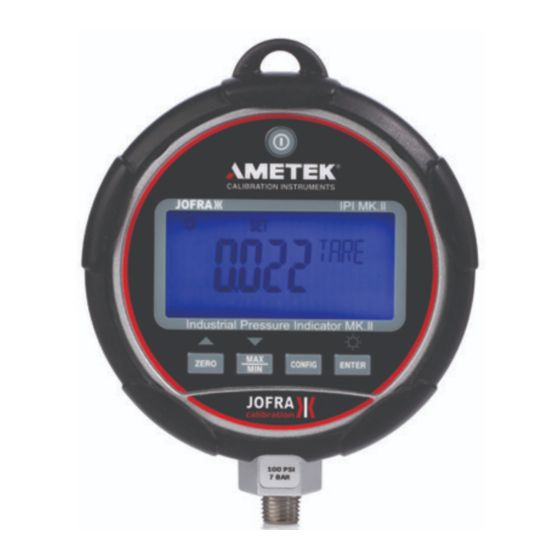
2.0 IPI Mk. II Display and Controls Turns Power on/off Pressure display Enters set-up and configuration menus CALIBRATION INSTRUMENTS JOFRA IPI MK.II Engineering Units Zeros the display, Scrolls forward through 0 - 100% bar graph menu displays Industrial Pressure Indicator MK.II Selects an action in Recalls min and max configuration. - Page 7 2. Set Auto Off. The auto-shut off can be set in 1 minute increments from 1 to 30 minutes or “off” (continuous operation). The unit is shipped set for 30 minutes. Use the ▲ and ▼ keys to set the desired interval. The “off”...
-
Page 8: Supervisory Mode
4.0 Supervisory Mode Push the CONFIG button to access the user-settable functions on the indicator. Each time the CONFIG button is pressed; the display advances to the next function. Press CONFIG repeatedly until “FUnC LOCK” is displayed. Press ENTER when “FUnC LOCK” is displayed, PWRD will be displayed on the gauge. -
Page 9: Normal Operation
5.0 Normal Operation Turning the backlight on and off: Press the ENTER button. Zeroing the display: Press and hold the ZERO button. Note: For absolute versions of the gauge pressing the zero key will prompt the user to enter a barometric reference pressure. Use the ▲ and ▼ arrow to adjust the reading as required. -
Page 10: Changing The Batteries
6.0 Changing the Batteries WARNING Explosion hazard Batteries must only be changed in an area known to be non-hazardous. Loosen the captive screw on the battery door, then remove the battery door to expose the 3 AA batteries. Replace the batteries as required and then reinstall the battery door and tighten the captive screw. -
Page 11: Specifications
8.0 Specifications All specifications cover the temperature range from 0°C to +50°C, unless otherwise noted. Available Input Ranges See page 13 for a table of available ranges in PSI plus equivalent ranges and resolution for all engineering units Accuracy Positive Pressure: ±0.05% FS Vacuum: 100, 300, 500 PSI indicator / 7, 21, 35 bar indicator: ±0.25% F.S. -
Page 12: Service Center Calibration Or Repair
Humidity: 10% to 95% RH Non-condensing Pollution: Degree II Mechanical Dimensions: 11.4 x 12.7 (cm), depth = 3.7 cm (4.5 x 5 (in), depth= 1.5 in) Pressure Connection: ¼” NPT Male Housing: cast ZNAL, meets NEMA 4/IP65 Display 5-1/2 Digits, 0.65” (16.53 mm) high 20-Segment bar graph, 0 to 100% Power Battery: three (3), size AA alkaline batteries... -
Page 14: Ipi Mk. Ii Serial Interface Instructions
11.0 IPI Mk. II Serial Interface Instructions Warning To prevent possible electrical shock, fire, or personal injury, do not use the RS-232 interface in hazardous areas. Initiating Communication The terminal communications can be setup using terminal communication software on a PC. The terminal settings need to be set as follows: •... - Page 15 HC_COMP_ON Turns temperature compensation on. HC_COMP? Returns state of temperature compensation. HC_RD_2410? Return 2410 ADC counts. HC_SI_OFF Turns SI mode off. HC_SI_ON Turns SI mode on. CAL_STORE Stores calibration data. HC_AUTO_OFF Turns auto shutdown off HC_AUTO_ON Turns auto shutdown on CUST_MULT? Sets the multiplier for the custom unit type STREAM_OFF...
-
Page 16: Warranty
AMETEK Denmark’s liability is restricted to errors that originated from the factory. When returning the calibrator to the manufacturer for service, please enclose a fully completed service information form. - Page 17 Special requests:_____________________________________________________ ___________________________________________________________________ Safety precautions: if the product has been exposed to any hazardous substances, it must be thoroughly decontaminated before it is returned to AMETEK. Details of the hazardous substances and any precautions to be taken must be enclosed.
- Page 19 SPK-IPI-004 0200044 Rev. A ATEX 10/12...
- Page 20 AMETEK Instruments India Pvt Ltd. Tel +86 20 8363 4768 Tel +49 (0)2159 9136 510 Tel +91 22 2836 4750 lloyd@ametek.com.cn info.mct-de@ametek.de jofra@ametek.com Information in this document is subject to change without notice. ©2012, by AMETEK, Inc., www.ametek.com. All rights reserved.
Need help?
Do you have a question about the JOFRA IPI Mk. II and is the answer not in the manual?
Questions and answers