Advertisement
Quick Links
Montageanleitung (Original)
Installation Instructions (Translation based on Original Documentation)
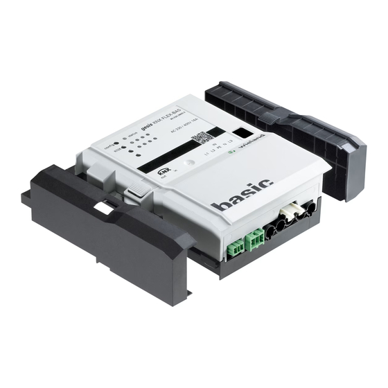
gesis
KNX FLEX-BAS
KNX-Basismodul mit AC-Einspeisung / KNX base module with AC power supply
3-phasig / 3-phase
83.020.0600.0
1-phasig (SP) / 1-phase (SP)
83.020.0601.0
• Nur Elektrofachkräfte dürfen dieses Gerät installieren und in Betrieb nehmen. Vor
Ausführung müssen sie diese Anleitung gelesen und verstanden haben.
• Gerät nicht öffnen. Keine Fremdobjekte einführen. Gerät von Wasser und Feuer fernhalten.
• Gerät nur in spannungsfreiem Zustand anschließen oder trennen.
• Die einschlägigen Normen, Richtlinien, Vorschriften und Bestimmungen des jeweiligen
Landes sind zu beachten.
Das KNX-Basismodul im flachen, tragschienenmontierbaren AP-Gehäuse zum dezentralen
Einbau unterstützt 6 Erweiterungsmodule. Sie verfügen über alle gängigen Ein-/Ausgänge und
ermöglichen mit nur einer physikalischen Adresse eine umfassende Raumautomation. Die
Handbedienebene erlaubt Funktionstests ohne vorherige Systemintegration. Die nach IEC
61535 steckbaren, elektrischen Verbindungen trennen Automation und Installation.
Hinweis: Funktionstests direkt nach Montage mit der Vorortbedienung an den Geräten ohne
Programmierung möglich.
Bedien- und Funktionselemente (siehe Rückseite, Abbildung 1)
• Tastendruck > 3s: Vergibt Moduladressen und Parameter.
Taster 'Config'
• Kurzer Tastendruck: Vergibt Parameter erneut.
(Voraussetzung: Moduladressen wurden bereits vergeben.)
LED 'Status'
Signalisiert den Systemstatus.
• Grün: Fehlerfreier Betrieb
• Rot: Fehlermeldung
• Modul 83.020.0600.0: Stecker GST18i5
Netzeingang
• Modul 83.020.0601.0: Stecker GST18i3
(Montage: siehe Rückseite, Abbildung 3)
Eingang KNX-Bus
Buchse BST14i2, 2-polig, grüne Codierung (Montage: Abbildung 3)
Ausgang KNX-Bus
Stecker BST14i2, 2-polig, grüne Codierung (Montage: Abbildung 3)
Taster 'KNX'
Startet den Programmiermodus für die physikalischen Adressen.
Details: siehe Handbuch
LED 'KNX''
Leuchtet im Programmiermodus rot.
Rastfuß
Arretierung für Montage auf Tragschiene/Montagerahmen
Montage (siehe Rückseite, Abbildung 2)
Schritt 1: Module Stecken
Endkappe links auf Basismodul setzen und einrasten.
1.1
Zusatzmodule in gewünschter Reihenfolge rechts an das Basismodul setzen und mit
1.2
hörbarem Klick einrasten.
Endkappe auf letztes Modul rechts aufsetzen und einrasten.
1.3
Schritt 2: Optional: Befestigung auf Tragschiene oder Montagerahmen
An jedem Modul mit Schraubendreher den Rastfuß nach oben ziehen.
2.1
Module auf Tragschiene aufsetzen.
2.2
An jedem Modul mit Schraubendreher den Rastfuß nach unten drücken.
2.3
Die Module sind auf der Tragschiene befestigt.
Schritt 3: Kabel stecken und sichern
Am Basismodul Bus- und Netzkabel stecken (Abbildung 1):
3.1
Ausgang KNX-Bus (grün)
Eingang KNX-Bus (grün),
Kabel an allen weiteren Modulen stecken (Siehe: Montageanleitungen).
3.2
Wichtig: Festen Sitz aller Steckverbindungen sicherstellen.
Bei Montagerahmen: Leitungen mit Kabelbindern am Montagerahmen befestigen.
3.3
Technische Daten
Netzanschluss
Bemessungsspannung
1-phasig (83.020.0601.0)
230 VAC, -15 % / +10 %, 50/60 Hz (GST18i3)
3-phasig (83.020.0600.0)
230 V / 400 VAC, -15 % / +10 %, 50/60 Hz (GST18i5)
Bemessungsstrom
16 A je Phase
Empfohlene Absicherung
1/3-poliger Leitungsschutzschalter B16A
KNX-Busanschluss
Busspannung
24 VDC (-10 % / + 20 %)
Stromaufnahme (KNX-Bus) Maximal 5 mA
Topologie
Twisted Pair TP1
Umweltbedingungen
Einsatzbereich
Innenräume und trockene Räume, wettergeschützt
Klimabeständigkeit
Klasse 3K5 (EN 50491-2)
Umgebungstemperatur
-5 °C bis +45 °C
Lagertemperatur
-25 °C bis +75 °C
Montageart
Decken-, Boden-, Wandmontage, feste Installation, Aufputz, auf
ebene Fläche, Tragschiene TH35-7,5, Montagerahmen
Gehäuse
Material
Kunststoff, halogenfrei
Farbe
Lichtgrau, ähnlich RAL 7035 / Schwarz, ähnlich RAL 9005
Brandverhalten
UL94 V-2
Brandlast
ca. 2 kWh
Abmessungen (B, H, L)
95*
)
mm, 149 mm, 44 mm
Elektrische Sicherheit
Schutzklasse
I
Schutzart
IP20 (nach EN 60529)
Verschmutzungsgrad
2
Überspannungskategorie
III
Zulassungen
KNX
KNX zertifiziert
CE-Kennzeichnung
Gemäß EMV-Richtlinie und Niederspannungsrichtlinie
Erfüllt Normen: EN 50491-5-1, EN 50491-5-2, EN 50491-5-3
Handbuch
mit detaillierten Informationen zu Programmierung, Inbetriebnahme und
Wartung:
• Dokumentnummer: BA000903
• Download über QR-Code oder:
http://eshop.wieland-electric.com/product/83.020.0600.0
http://eshop.wieland-electric.com/product/83.020.0601.0
Doc. # BA000896 - 08/2013 (Rev. A)
GEFA H R
Netzeingang (schwarz)
*
)
117mm mit Endkappe links
Wieland Electric GmbH
Brennerstraße 10-14
96052 Bamberg
Tel.:
+49 (951) 9324-0
Fax:
+49 (951) 9324-198
Internet: www.wieland-
electric.com
Email: info@wieland-electric.com
• Only trained electricians may install and commission this device. They must have read and
understood this instruction manual before they carry out installation.
• Do not open the device. Do not insert any foreign objects. Keep the device away from
water and fire.
• Only connect or disconnect the device if it has been de-energised.
• The relevant standards, directives, regulations and provisions of the particular country are
to be observed.
The KNX base module in the flat AP housing, which can be fitted on DIN rails for decentralised
installation, supports 6 extension modules. They have all the common inputs and outputs, and
they provide extensive room automation with only one physical address. The manual operation
level allows function tests without prior system integration. The electrical connections, which
are pluggable in accordance with IEC 61535, separate automation and installation.
Note: Function tests directly after installation are possible on the devices with the manual
operation level and without programming.
Operating and functional elements (see back page, figure 1)
'Config' button
LED for 'Status'
Mains input
Input for KNX bus
Output for KNX bus Plug BST14i2, 2-pole, green coding (installation: figure 3)
'KNX' button
LED for 'KNX'
Resting foot
Installation (see back page, figure 2)
Step 1: Plugging in modules
Place the end cap on the left of the base module and latch it into place.
1.1
Place additional modules in the desired sequence on the right of the base module and
1.2
latch them into place with an audible click.
Place the end cap on the last module on the right and latch it into place.
1.3
Step 2: Optional: Fastening on DIN rail or mounting frame
Pull the resting foot on every module upwards with a screwdriver.
2.1
Place the modules on the DIN rail.
2.2
Press the resting foot on every module downwards with a screwdriver.
2.3
The modules are now fastened on the DIN rail.
Step 3: Plugging in cables and securing them
Plug in the bus cable and mains cable to the base module (figure 1):
3.1
Output for KNX bus (green),
Plug in cables to all further modules (see installation instructions).
3.2
Important: Ensure that all plug-in connections are securely seated.
In the case of a mounting frame: Fasten cables with cable ties to the mounting frame.
3.3
Technical data
Mains connection
Rated voltage
1-phase (83.020.0601.0)
3-phase (83.020.0600.0)
Rated current
Recommended fuse protec-
tion
Connection for KNX bus
Bus voltage
Current consumption (KNX
bus)
Topology
Ambient conditions
Area of application
Climate resistance
Ambient temperature
Storage temperature
Type of installation
Housing
Material
Colour
Reaction to fire
Fire load
Dimensions (W, H, L)
Electrical safety
Protection class
Protection type
Contamination level
Overvoltage category
Approvals
KNX
CE marking
Handbook
with detailed information on programming, commissioning and mainte-
nance:
• Document number: BA000904
• Download via QR code or:
http://eshop.wieland-electric.com/product/83.020.0600.0
http://eshop.wieland-electric.com/product/83.020.0601.0
gesis KNX FLEX-BAS
DA N GER
• Pressing the button > 3s: Allocates module addresses and
parameters.
• Pressing the button briefly: Allocates the parameters again.
(Precondition: The module addresses have already been allocated.)
Signals the system status.
• Green: Fault-free operation
• Red: Fault message
• Module 83.020.0600.0: plug GST18i5
• Module 83.020.0601.0: plug GST18i3
(installation: see back page, figure 3)
Socket BST14i2, 2-pole, green coding (installation: figure 3)
Starts the programming mode for the physical addresses.
Details: See handbook
Lights up red in programming mode.
Locking mechanism for installing on DIN rail/mounting frame
Input for KNX bus (green),
230 VAC, -15 % / +10 %, 50/60 Hz (GST18i3)
230 V / 400 VAC, -15 % / +10 %, 50/60 Hz (GST18i5)
16 A each phase
1/3-phase circuit breaker B16A
24 VDC (-10 % / + 20 %)
Maximum 5 mA
Twisted Pair TP1
Internal rooms and dry rooms, protected from weather
Class 3K5 (EN 50491-2)
-5 °C to +45 °C
-25 °C to +75 °C
Installation on ceiling, floor and wall, fixed installation, surface-
mounted, on level surface, DIN rail TH35-7.5, mounting frame
Plastic, halogen-free
Light grey, similar to RAL 7035 / Black, similar to RAL 9005
UL94 V-2
approx. 2 kWh
95*
)
mm, 149 mm, 44 mm
I
IP20 (in accordance with EN 60529)
2
III
KNX certified
In accordance with EMC Directive and Low Voltage Directive
Meets standards: EN 50491-5-1, EN 50491-5-2, EN 50491-5-3
input Mains (black)
*
)
117mm with left end cap
DE/EN 1
Advertisement

Related Manuals for Wieland gesis KNX FLEX-BAS


Summary of Contents for Wieland gesis KNX FLEX-BAS
- Page 1 Wartung: nance: • Dokumentnummer: BA000903 • Document number: BA000904 • Download über QR-Code oder: • Download via QR code or: http://eshop.wieland-electric.com/product/83.020.0600.0 http://eshop.wieland-electric.com/product/83.020.0600.0 http://eshop.wieland-electric.com/product/83.020.0601.0 http://eshop.wieland-electric.com/product/83.020.0601.0 Doc. # BA000896 - 08/2013 (Rev. A) gesis KNX FLEX-BAS DE/EN 1...
- Page 2 Figure 3: Installation of the plugs Netzanschluss / Mains connection KNX-Anschluss / KNX connection GST18i3 (92.923.3035.1) GST18i5 (92.953.4053.1) BST14i2 (93.422.0553.1) Drehmoment 0,5 … 0,7 Nm Torque 4,4 … 6,2 lb-in Doc. # BA000896 - 08/2013 (Rev. A) gesis KNX FLEX-BAS DE/EN 2...
- Page 3 : manutenzione: • Numéro de document : BA000904 • Documento numero: BA000904 • Téléchargement via QR ou : • Download mediante codice QR o: http://eshop.wieland-electric.com/product/83.020.0600.0 http://eshop.wieland-electric.com/product/83.020.0600.0 http://eshop.wieland-electric.com/product/83.020.0601.0 http://eshop.wieland-electric.com/product/83.020.0601.0 Doc. # BA000896 - 08/2013 (Rev. A) gesis KNX FLEX-BAS FR/IT 1...
- Page 4 Raccordement secteur / Collegamento di rete Raccordement KNX / Collegamento KNX GST18i3 (92.923.3035.1) GST18i5 (92.953.4053.1) BST14i2 (93.422.0553.1) Couple 0,5 … 0,7 Nm Coppia di 4,4 … 6,2 lb-in serraggio Doc. # BA000896 - 08/2013 (Rev. A) gesis KNX FLEX-BAS FR/IT 2...
Need help?
Do you have a question about the gesis KNX FLEX-BAS and is the answer not in the manual?
Questions and answers