Advertisement
Quick Links
Montageanleitung (Original)
Installation Instructions (Translation based on Original Documentation)
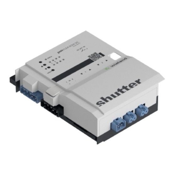
gesis
FLEX-0/2W DC
2-fach Jalousieausgang
(83.020.0627.0)
2-fold shutter output
(83.020.0627.0)
• Nur Elektrofachkräfte dürfen dieses Gerät installieren und in Betrieb nehmen. Vor
Ausführung müssen sie diese Anleitung gelesen und verstanden haben.
• Gerät nicht öffnen. Keine Fremdobjekte einführen. Gerät von Wasser und Feuer fernhalten.
• Gerät nur in spannungsfreiem Zustand anschließen oder trennen.
• Die einschlägigen Normen, Richtlinien, Vorschriften und Bestimmungen des jeweiligen
Landes sind zu beachten.
Der DC-Jalousieausgang 2-fach 24 VDC/3 A im flachen, auf Tragschiene montierbaren AP-
Gehäuse zum dezentralen Einbau, wird vom Basismodul verwaltet und erhält die Busversor-
gung vom vorgeschalteten Modul. Die 24 VDC-Versorgung erfolgt von extern. Der umfangrei-
che Parametersatz ermöglicht verschiedene Automationsfunktionen. Die nach IEC 61535
steckbaren elektrischen Verbindungen trennen Automation und Installation.
Hinweis: Funktionstests direkt nach Montage mit der Vorortbedienung an den Geräten ohne
Programmierung möglich.
Bedien- und Funktionselemente (siehe Rückseite, Abbildung 1)
Taster 'select'
Wählt einen Jalousieausgang.
Der gewählte Ausgang beginnt zu blinken.
Taster ▼
• Tastendruck > 500ms: Fährt Jalousie nach unten.
• Tastendruck < 500ms: Lamellenbewegung oder Stopp
Taster ▲
• Tastendruck > 500ms: Fährt Jalousie nach oben.
• Tastendruck < 500ms: Lamellenbewegung oder Stopp
LED '1'
Signalisiert die Fahrrichtung und den Status der Jalousiebewegung.
▲: Fahrbewegung aufwärts
LED '2'
▼: Fahrbewegung abwärts
LED 'status'
Signalisiert den Betriebszustand des Erweiterungsmoduls.
• Grün: Modul funktionsbereit (kein Fehler).
• Rot: Fehlermeldung
Rastfuß
Arretierung für Montage auf Tragschiene/Montagerahmen
Jalousieausgang • 2 Anschlüsse für Stecker GST15i2 lichtblau (91.921.3353.0)
(Montage: siehe Rückseite, Abbildung 3)
• Anschluss der Versorgungsspannung 5 bis 24 VDC für die Jalousie-
DC-Einspeisung
antriebe mit Stecker GST15i2 lichtblau (91.922.3353.0)
Montage (siehe Rückseite, Abbildung 2)
Schritt 1: Module Stecken
Endkappe links auf Basismodul setzen und einrasten.
1.1
Zusatzmodule in gewünschter Reihenfolge rechts an das Basismodul setzen und mit
1.2
hörbarem Klick einrasten.
Endkappe auf letztes Modul rechts aufsetzen und einrasten.
1.3
Schritt 2: Optional: Befestigung auf Tragschiene oder Montagerahmen
An jedem Modul mit Schraubendreher den Rastfuß nach oben ziehen.
2.1
Module auf Tragschiene aufsetzen.
2.2
An jedem Modul mit Schraubendreher den Rastfuß nach unten drücken.
2.3
Die Module sind auf der Tragschiene befestigt.
Schritt 3: Kabel stecken und sichern
Am Modul die Kabel
stecken.
3.1
Kabel an allen weiteren Modulen stecken (Siehe: Montageanleitungen).
3.2
Wichtig: Festen Sitz aller Steckverbindungen sicherstellen.
Bei Montagerahmen: Kabel mit Kabelbindern am Montagerahmen befestigen.
3.3
Technische Daten
Netzanschluss
Netzversorgung AC
230 VAC, -15 % / +10 %, 50/60 Hz (für Folgemodule)
Ausgänge
Bemessungsspannung
5 bis 24V DC (Versorgung über externes Netzteil)
Bemessungsstrom
3 A je Kanal
6 A als Summenstrom beider Ausgänge
Empfohlene Absicherung
6,3 A T (träge in DC-Zuleitung)
Umweltbedingungen
Einsatzbereich
Innenräume und trockene Räume, wettergeschützt
Klimabeständigkeit
Klasse 3K5 (EN 50491-2)
Umgebungstemperatur
-5 °C bis +45 °C
Lagertemperatur
-25 °C bis +75 °C
Montageart
Decken-, Boden-, Wandmontage, feste Installation, Aufputz, auf
ebene Fläche, Tragschiene TH35-7,5, Montagerahmen
Gehäuse
Material
Kunststoff, halogenfrei
Farbe
Lichtgrau, ähnlich RAL 7035 / Schwarz, ähnlich RAL 9005
Brandverhalten
UL94 V-2
Brandlast
ca. 2 kWh
)
Abmessungen (B, H, L)
95*
mm, 149 mm, 44 mm
Elektrische Sicherheit
Schutzklasse
I
Schutzart
IP20 (nach EN 60529)
Verschmutzungsgrad
2
Überspannungskategorie
III
Zulassungen
CE-Kennzeichnung
Gemäß EMV-Richtlinie und Niederspannungsrichtlinie
Erfüllt Normen: EN 50491-5-1, EN 50491-5-2, EN 50491-5-3
Handbuch
mit detaillierten Informationen zu Programmierung, Inbetriebnahme und
Wartung:
• Dokumentnummer: BA000903
• Download über QR-Code oder:
http://eshop.wieland-electric.com/product/83.020.0627.0
Doc. # BA000899 - 05/2014 (Rev. A)
GEFA H R
*
)
105mm mit Endkappe rechts
Wieland Electric GmbH
Brennerstraße 10-14
96052 Bamberg
Tel.:
+49 (951) 9324-0
Fax:
+49 (951) 9324-198
Internet: www.wieland-electric.com
Email: info@wieland-electric.com
• Only trained electricians may install and commission this device. They must have read and
understood this instruction manual before they carry out installation.
• Do not open the device. Do not insert any foreign objects. Keep the device away from
water and fire.
• Only connect or disconnect the device if it has been de-energised.
• The relevant standards, directives, regulations and provisions of the particular country are
to be observed.
The 2-fold DC shutter output 24 VDC/3 A in the flat AP housing, which can be fitted on carrier
rails for decentralised installation, is administered by the base module and receives bus power
from the upstream module. The 24 VDC power supply is external. The extensive parameter set
enables different automation functions. The electrical connections, which are pluggable in
accordance with IEC 61535, separate automation and installation.
Note: Function tests directly after installation are possible on the devices with on-site opera-
tion and without programming.
Operating and functional elements (see back page, figure 1)
'select' button
Selects one shutter output.
The selected output begins to flash.
Button ▼
• Pressing the button > 500ms: Moves the shutter downwards.
• Pressing the button < 500ms: lamella movement or stop
Button ▲
• Pressing the button > 500ms: Moves the shutter upwards.
• Pressing the button < 500ms: lamella movement or stop
LED '1'
Signals the movement direction and the status of the shutter move-
LED '2'
ment.
▲: Movement upwards
▼: Movement downwards
LED 'status'
Signals the operating status of the extension module.
• Green: Module ready to function (no fault).
• Red: Fault message
Resting foot
Locking mechanism for installing on carrier rail/mounting frame
• 2 connections for plug GST15i2 light blue (91.921.3353.0)
Shutter output
• Connection of power supply 5 to 24 VDC for the shutter drive with
DC power feed
Installation (see back page, Figure 2)
Step 1: Plugging in modules
Place the end cap on the left of the base module and latch it into place.
1.1
Place the additional module in the desired order on the right of the base module and latch
1.2
it into place with an audible click.
Place the end cap on the last module on the right and latch it into place.
1.3
Step 2: Optional: Fastening on carrier rail or mounting frame
Pull the resting foot on every module upwards with a screwdriver.
2.1
Set the modules onto the carrier rail.
2.2
Press the resting foot on every module downward with a screwdriver.
2.3
The modules are now fastened on the carrier rail.
Step 3: Plugging in cables and securing them
Plug in cable
to the module.
3.1
Plug in cables at all other modules (see: installation instructions).
3.2
Important: Ensure that all plug-in connections are securely seated.
For mounting frames: fix to mounting frame with cable binders.
3.3
Technical Data
Mains connection
Mains supply AC
Outputs
Rated voltage
Rated current
Recommended fuse protec-
tion
Environmental conditions
Area of application
Climate resistance
Ambient temperature
Storage temperature
Type of installation
Housing
Material
Colour
Reaction to fire
Fire load
Dimensions (W, H, L)
Electrical safety
Protection class
Protection type
Contamination level
Over-voltage category
Approvals
CE marking
Handbook
with detailed information on programming, commissioning and mainte-
nance:
• Document number: BA000904
• Download via QR code or:
http://eshop.wieland-electric.com/product/83.020.0627.0
gesis
FLEX-0/2W DC
DA N GER
(Installation: see back page, Figure 3)
plug GST15i2 light blue (91.922.3353.0)
230 VAC, -15 % / +10 %, 50/60 Hz (for the subsequent modules)
5 to 24V DC (power supply through external power source)
3 A per channel
6 A as a total current for both outputs
6.3 A T (slow in DC feed line)
Internal rooms and dry rooms, protected from weather
Class 3K5 (EN 50491-2)
-5 °C to +45 °C
-25 °C to +75 °C
Installation on ceiling, floor and wall, fixed installation, surface-
mounted, on level surface, carrier rail TH35-7.5, mounting frame
Plastic, halogen-free
Light grey, similar to RAL 7035 / Black, similar to RAL 9005
UL94 V-2
approx. 2 kWh
95*
)
mm, 149 mm, 44 mm
I
IP20 (in accordance with EN 60529)
2
III
In accordance with EMC Directive and Low Voltage Directive
Meets standards: EN 50491-5-1, EN 50491-5-2, EN 50491-5-3
*
)
105 mm with right end cap
DE/EN 1
Advertisement

Subscribe to Our Youtube Channel
Related Manuals for Wieland GESIS FLEX-0/2W DC


Summary of Contents for Wieland GESIS FLEX-0/2W DC
- Page 1 Montageanleitung (Original) Wieland Electric GmbH Installation Instructions (Translation based on Original Documentation) Brennerstraße 10-14 96052 Bamberg gesis FLEX-0/2W DC Tel.: +49 (951) 9324-0 Fax: +49 (951) 9324-198 2-fach Jalousieausgang (83.020.0627.0) Internet: www.wieland-electric.com 2-fold shutter output (83.020.0627.0) Email: info@wieland-electric.com GEFA H R DA N GER •...
- Page 2 Montageanleitung (Original) Wieland Electric GmbH Installation Instructions (Translation based on Original Documentation) Brennerstraße 10-14 96052 Bamberg gesis FLEX-0/2W DC Tel.: +49 (951) 9324-0 Fax: +49 (951) 9324-198 2-fach Jalousieausgang (83.020.0627.0) Internet: www.wieland-electric.com 2-fold shutter output (83.020.0627.0) Email: info@wieland-electric.com Abbildung 1: Bedien- und Funktionselemente...
- Page 3 Instructions de montage (Traduction de la notice originale) Wieland Electric GmbH Istruzioni per il montaggio (Traduzione delle istruzioni originali) Brennerstraße 10-14 96052 Bamberg gesis FLEX-0/2W DC Tel.: +49 (951) 9324-0 Fax: +49 (951) 9324-198 Sortie de store 2 postes (83.020.0627.0) Internet: www.wieland-electric.com...
- Page 4 Instructions de montage (Traduction de la notice originale) Wieland Electric GmbH Istruzioni per il montaggio (Traduzione delle istruzioni originali) Brennerstraße 10-14 96052 Bamberg gesis FLEX-0/2W DC Tel.: +49 (951) 9324-0 Fax: +49 (951) 9324-198 Sortie de store 2 postes (83.020.0627.0) Internet: www.wieland-electric.com...
Need help?
Do you have a question about the GESIS FLEX-0/2W DC and is the answer not in the manual?
Questions and answers