Siemens Simotics T-1FW6 Operating Instructions Manual
Built-in torque motors
Hide thumbs
Also See for Simotics T-1FW6:
- Configuration manual (560 pages) ,
- Operating instructions manual (138 pages) ,
- Configuration manual (174 pages)
Table of Contents
Advertisement
Quick Links
Advertisement
Table of Contents

Subscribe to Our Youtube Channel
Related Manuals for Siemens Simotics T-1FW6


Summary of Contents for Siemens Simotics T-1FW6
- Page 3 Introduction Fundamental safety instructions Description SIMOTICS Preparation for use Drive technology 1FW6 external rotor built-in Installation torque motors Connection Operating Instructions Commissioning Operation Maintenance Decommissioning and disposal Appendix 12/2020 A5E49196960B AB...
- Page 4 Note the following: WARNING Siemens products may only be used for the applications described in the catalog and in the relevant technical documentation. If products and components from other manufacturers are used, these must be recommended or approved by Siemens. Proper transport, storage, installation, assembly, commissioning, operation and maintenance are required to ensure that the products operate safely and without any problems.
-
Page 5: Introduction
These operating instructions complement the relevant Siemens configuration manual. Siemens strives continually to improve the quality of information provided in these operating instructions. • If you find any mistakes or would like to offer suggestions about how this document could be improved, contact the Siemens Service Center. - Page 6 Introduction Enumerations • Enumerations are identified by a bullet point without any additional symbols. – Enumerations at the second level are hyphenated. Notes Notes are shown as follows: Note A Note is an important item of information about the product, handling of the product or the relevant section of the document.
- Page 7 E-mail (mailto:docu.motioncontrol@siemens.com). My support Information on how to produce individual contents for your own machine documentation based on Siemens contents is available under the link: My support (https://support.industry.siemens.com/My/de/en/documentation) Note If you want to use this function, you must register once.
- Page 8 Siemens does not control the information on these websites and is not responsible for the content and information provided there. The user bears the risk for their use.
-
Page 9: Table Of Contents
Table of contents Introduction ............................. 3 Fundamental safety instructions ......................11 General safety instructions ..................... 11 Equipment damage due to electric fields or electrostatic discharge ........17 Security information ........................ 18 Residual risks of power drive systems ..................19 Description ............................21 Intended use ........................... - Page 10 Table of contents Installation ............................57 Safety guidelines relating to installation ................. 57 Forces that occur between the stator and rotor ..............61 Specifications for mounting torque motors ................63 Procedure for installing the motor ..................65 Checking the work performed ....................67 Connection ............................
- Page 11 Table of contents Appendix............................. 113 Recommended manufacturers ..................... 113 A.1.1 Manufacturers of anti-corrosion agents ................113 A.1.2 Manufacturers of spacer foils ....................113 List of abbreviations ......................114 Index..............................115 1FW6 external rotor built-in torque motors Operating Instructions, 12/2020, A5E49196960B AB...
- Page 12 Table of contents 1FW6 external rotor built-in torque motors Operating Instructions, 12/2020, A5E49196960B AB...
-
Page 13: Fundamental Safety Instructions
Fundamental safety instructions General safety instructions WARNING Electric shock and danger to life due to other energy sources Touching live components can result in death or severe injury. • Only work on electrical devices when you are qualified for this job. •... - Page 14 Fundamental safety instructions 1.1 General safety instructions WARNING Electric shock due to damaged motors or devices Improper handling of motors or devices can damage them. Hazardous voltages can be present at the enclosure or at exposed components on damaged motors or devices. •...
- Page 15 Therefore, if you move closer than 20 cm to the components, be sure to switch off radio devices or mobile telephones. • Use the "SIEMENS Industry Online Support app" only on equipment that has already been switched off. WARNING Unrecognized dangers due to missing or illegible warning labels Dangers might not be recognized if warning labels are missing or illegible.
- Page 16 Fundamental safety instructions 1.1 General safety instructions WARNING Unexpected movement of machines caused by inactive safety functions Inactive or non-adapted safety functions can trigger unexpected machine movements that may result in serious injury or death. • Observe the information in the appropriate product documentation before commissioning.
- Page 17 Fundamental safety instructions 1.1 General safety instructions WARNING Active implant malfunctions due to permanent-magnet fields Even when switched off, electric motors with permanent magnets represent a potential risk for persons with heart pacemakers or implants if they are close to converters/motors. •...
- Page 18 Fundamental safety instructions 1.1 General safety instructions CAUTION Burn injuries caused by hot surfaces In operation, the motor can reach high temperatures, which can cause burns if touched. • Mount the motor so that it is not accessible in operation. Measures when maintenance is required: •...
-
Page 19: Equipment Damage Due To Electric Fields Or Electrostatic Discharge
Fundamental safety instructions 1.2 Equipment damage due to electric fields or electrostatic discharge Equipment damage due to electric fields or electrostatic discharge Electrostatic sensitive devices (ESD) are individual components, integrated circuits, modules or devices that may be damaged by either electric fields or electrostatic discharge. NOTICE Equipment damage due to electric fields or electrostatic discharge Electric fields or electrostatic discharge can cause malfunctions through damaged... -
Page 20: Security Information
Siemens’ products and solutions undergo continuous development to make them more secure. Siemens strongly recommends that product updates are applied as soon as they are available and that the latest product versions are used. Use of product versions that are no longer supported, and failure to apply the latest updates may increase customer’s exposure... -
Page 21: Residual Risks Of Power Drive Systems
Fundamental safety instructions 1.4 Residual risks of power drive systems Residual risks of power drive systems When assessing the machine- or system-related risk in accordance with the respective local regulations (e.g., EC Machinery Directive), the machine manufacturer or system installer must take into account the following residual risks emanating from the control and drive components of a drive system: 1. - Page 22 Fundamental safety instructions 1.4 Residual risks of power drive systems For more information about the residual risks of the drive system components, see the relevant sections in the technical user documentation. 1FW6 external rotor built-in torque motors Operating Instructions, 12/2020, A5E49196960B AB...
-
Page 23: Description
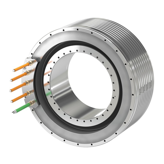
Description SIMOTICS T-1FW6 external rotor built-in torque motors are designed as built-in motors for use in low-speed direct drives with a high torque output. These built-in torque motors are liquid-cooled, permanent-magnet-excited, high-pole-number three-phase synchronous motors. The motors are delivered as components that are subsequently built-in. -
Page 24: Intended Use
Where relevant, take into account deviations regarding approvals or country-specific regulations. • Contact your local Siemens office if you have any questions relating to correct use. • If you wish to use special versions and design versions whose technical details vary from the motors described in this document, then you must contact your local Siemens office. - Page 25 Description 2.1 Intended use WARNING Injury and material damage by not observing machinery directive 2006/42/EC There is a risk of death, serious injury and/or material damage if machinery directive 2006/42/EC is not carefully observed. • The products included in the scope of delivery are exclusively designed for installation in a machine.
-
Page 26: Technical Features And Ambient Conditions
Description 2.2 Technical features and ambient conditions Technical features and ambient conditions 2.2.1 Standards and guidelines Standards that are complied with The motors of the type series SIMOTICS S, SIMOTICS M, SIMOTICS L, SIMOTICS T, SIMOTICS A, called "SIMOTICS motor series" below, fulfill the requirements of the following directives and standards: •... - Page 27 UL or cUL mark on the rating plate! Quality systems Siemens AG employs a quality management system that meets the requirements of ISO 9001 and ISO 14001. Certificates for SIMOTICS motors can be downloaded from the Internet at the following link: Certificates for SIMOTICS motors (https://support.industry.siemens.com/cs/ww/de/ps/13347/cert)
-
Page 28: Danger From Strong Magnetic Fields
Description 2.2 Technical features and ambient conditions 2.2.2 Danger from strong magnetic fields Occurrence of magnetic fields Motor components with permanent magnets generate very strong magnetic fields. In the no- current condition, the magnetic field strength of the motors comes exclusively from the magnetic fields of components equipped with permanent magnets. - Page 29 Description 2.2 Technical features and ambient conditions For magnetic fields, you must carefully comply with the requirements laid down in the DGUV regulation 103-013 of the German Social Accident Insurance. CAUTION Safety distance to the rotor The rotor magnetic fields are permanent. If you come into direct bodily contact with the rotors, a static magnetic flux density of 2 T is not exceeded.
- Page 30 Description 2.2 Technical features and ambient conditions WARNING Risk of rotor permanent magnets causing crushing injuries The forces of attraction of magnetic rotors act on materials that can be magnetized. The forces of attraction increase significantly close to the rotor. The response threshold of 3 mT for risk of injury through attraction and causing a projectile effect is reached at a distance of 100 mm (Directive 2013/35/EU).
- Page 31 Description 2.2 Technical features and ambient conditions Note Installation device Because of the numerous installation situations and installation constraints, it is not possible to specify a general joining fixture. First aid in the case of accidents involving permanent magnets • Stay calm. •...
-
Page 32: Technical Features
Description 2.2 Technical features and ambient conditions 2.2.3 Technical features Table 2- 1 Standard version of the 1FW67 built-in torque motor Technical feature Version Motor type Synchronous motor with permanent magnet rotor - with a high number of poles Design Individual components: stator, rotor Degree of protection according to Motor: IP23... -
Page 33: Defining The Direction Of Rotation
Description 2.2 Technical features and ambient conditions 2.2.4 Defining the direction of rotation Direction of rotation If the built-in torque motor is connected with phase sequence U-V-W, and is fed from a three-phase system with a clockwise phase sequence, then the rotor will rotate counterclockwise. -
Page 34: Ambient Conditions For Fixed Operation
Description 2.2 Technical features and ambient conditions 2.2.5 Ambient conditions for fixed operation You can classify the ambient conditions for stationary use at weatherprotected locations according to the standard IEC 60721-3-3. The environmental effects and their limit values are defined in various classes in this standard. With the exception of "Low air temperature"... -
Page 35: Degree Of Protection
Description 2.2 Technical features and ambient conditions You can find additional data on the environmental conditions, such as ambient temperatures or conditions for transport and storage of the motors, in the relevant chapters of this documentation. 2.2.6 Degree of protection NOTICE Damage to the motor caused by pollution If the area where the motor is installed is polluted and dirty, then the motor can malfunction... -
Page 36: Noise Emission
Description 2.2 Technical features and ambient conditions 2.2.7 Noise emission WARNING Hearing damage Hearing damage may occur if the motor exceeds a sound pressure level of 70 dB (A) due to the type of mounting or pulse frequency. • Reduce the sound pressure level by implementing sound damping and/or soundproofing measures. -
Page 37: Derating Factors
Description 2.3 Derating factors Derating factors For installation altitudes more than 2000 m above sea level, reduce the voltage stress of the motors according to the "Factors to reduce the maximum DC link voltage" table (reciprocal values from EN 60664-1 Table A. 2). Table 2- 3 Factors to reduce the maximum DC link voltage Installation altitude above sea level in m up to... -
Page 38: Rating Plate Data
Description 2.4 Rating plate data Rating plate data Technical data of the stator is provided on the rating plate (name plate). A second rating plate is provided loose for the stator. If, at a certain point in time, the stator and rotor are separated, then you must ensure that the stator and rotor can be assigned to one another at a later point in time. -
Page 39: Design
Description 2.5 Design Design 2.5.1 Motor components 2.5.1.1 Overview of the motor construction The built-in torque motor contains the following components: • Stator: comprises an iron core and a 3-phase winding. The winding is encapsulated to ensure that the heat loss can be dissipated more effectively. -
Page 40: Scope Of Delivery
Description 2.5 Design 2.5.2 Scope of delivery 2.5.2.1 1FW6 external rotor built-in torque motors • Rotor • Stator with ready-to-connect cooling system; one cable for the power connection and one cable for the signal connection with open core ends • Rating plate (attached); additional loose rating plate •... -
Page 41: Cooling
Description 2.5 Design 2.5.3 Cooling Note No motor operation without liquid cooling • Ensure that the torque motor cooling system functions perfectly. • Only operate the motor in conjunction with liquid cooling. 2.5.3.1 Cooling circuits Cooling circuit requirements Avoid algae growth by using suitable chemical agents and opaque water hoses. We recommend that the cooling circuits be designed as closed systems. - Page 42 Description 2.5 Design Recommended material for connecting coolers NOTICE Corrosion as a result of unsuitable materials used to connect the cooler Corrosion damage can occur if you use unsuitable materials to connect to the cooler. • We recommend that you use brass or stainless steel fittings when connecting the cooler.
-
Page 43: Coolants
Power derating when using oil as coolant If you are using oil as coolant, then this can reduce the power loss dissipated by the cooler. Appropriately reduce the motor power. Please contact your local Siemens office if you have any questions. - Page 44 Description 2.5 Design General requirements placed on the cooling medium The cooling medium must be pre-cleaned or filtered in order to prevent the cooling circuit from becoming blocked. The formation of ice is not permitted! Note The maximum permissible size for particles in the cooling medium is 100 μm. Requirements placed on the water Water which is used as basis for the coolant must comply as a minimum with the following requirements:...
-
Page 45: Temperature Monitoring And Thermal Motor Protection
Description 2.5 Design 2.5.4 Temperature monitoring and thermal motor protection 2.5.4.1 Temperature monitoring circuits Temp-S and Temp-F The motors are equipped with the two temperature monitoring circuits – Temp-S and Temp-F – that are described below. • Temp-S activates the thermal motor protection when the motor windings are thermally overloaded. - Page 46 Description 2.5 Design Note Shutdown time If Temp-S responds, and its response threshold is not undershot again in the meantime, then the drive system must shut down (de-energize) the motor within 2 seconds. This prevents the motor windings from becoming inadmissibly hot. NOTICE Motor destroyed as a result of overtemperature The motor can be destroyed if the motor winding overheats.
-
Page 47: Technical Features Of Temperature Sensors
Description 2.5 Design No direct connection of the temperature monitoring circuits WARNING Risk of electric shock when incorrectly connecting the temperature monitoring circuit In the case of a fault, circuits Temp-S and Temp-F do not provide safe electrical separation with respect to the power components. •... - Page 48 Description 2.5 Design Table 2- 7 Technical data of the PTC temperature sensors Name Description Type PTC triplet acc. to DIN 44082 Individual PTC temperature sensor according to DIN 44081 Response threshold 130 °C ± 5 K (nominal response temperature ϑ 80 °C ±...
- Page 49 Description 2.5 Design Technical features of the Pt1000 temperature sensor The Pt1000 has a linear temperature resistance characteristic. In addition, the Pt1000 has a low thermal capacity and provides good thermal contact with the motor winding. Table 2- 8 Technical data of the Pt1000 PTC thermistor Name Description Type...
- Page 50 Description 2.5 Design 1FW6 external rotor built-in torque motors Operating Instructions, 12/2020, A5E49196960B AB...
-
Page 51: Preparation For Use
Preparation for use WARNING Risk of death and crushing as a result of permanent magnet fields Severe injury and material damage can result if you do not take into consideration the safety instructions relating to permanent magnet fields. • Refer to Chapter "Danger from strong magnetic fields (Page 26)". Keep these operating instructions so that they are accessible at all times. - Page 52 • Report any apparent defects / missing components to the appropriate Siemens office immediately. Siemens will not accept any claims relating to items missing from the delivery and which are submitted at a later date. 1FW6 external rotor built-in torque motors...
-
Page 53: Shipping And Packaging
Preparation for use 3.1 Shipping and packaging Shipping and packaging When shipping products that contain permanent magnets by sea or road, no additional packaging measures are required for protection against magnetic fields. Dangers are marked as follows on the original packaging of 1FW6 rotors: Table 3- 1 Warning signs according to BGV A8 and EN ISO 7010 and their significance Sign... - Page 54 Preparation for use 3.1 Shipping and packaging Note Original packaging Keep the packaging of components with permanent magnets where possible! When reusing the original packaging do not cover safety instructions that are possibly attached. When required, use transparent adhesive tape for the packaging. 1FW6 external rotor built-in torque motors Operating Instructions, 12/2020, A5E49196960B AB...
-
Page 55: Transporting And Storage
Preparation for use 3.2 Transporting and storage Transporting and storage Note UN number for permanent magnets UN number 2807 is allocated to permit magnets as hazardous item. NOTICE Damage to the motor when incorrectly lifted Improper use of lifting devices can cause plastic deformation of the motor. •... -
Page 56: Packaging Specifications For Air Transportation
Preparation for use 3.2 Transporting and storage 3.2.1 Packaging specifications for air transportation When transporting products containing permanent magnets by air, the maximum permissible magnetic field strengths specified by the appropriate IATA Packing Instruction must not be exceeded. Special measures may be required so that these products can be shipped. Above a certain magnetic field strength, shipping requires that you notify the relevant authorities and appropriately label the products. - Page 57 Preparation for use 3.2 Transporting and storage Table 3- 5 Biological ambient conditions Long-term storage: Class 1B1 Transport: Class 2B1 Table 3- 6 Chemical ambient conditions Long-term storage: Class 1C1 Transport: Class 2C1 Table 3- 7 Mechanically active ambient conditions Long-term storage: Class 1S2 Transport:...
-
Page 58: Storage
Preparation for use 3.2 Transporting and storage 3.2.3 Storage The motors can be stored for up to two years under the following conditions: Storing indoors • Apply a preservation agent (e.g. Tectyl) to bare external components if this has not already been carried out in the factory. -
Page 59: Installation
Installation Safety guidelines relating to installation WARNING Risk of death and crushing as a result of permanent magnet fields Severe injury and material damage can result if you do not take into consideration the safety instructions relating to permanent magnet fields. •... - Page 60 Installation 4.1 Safety guidelines relating to installation WARNING Risk of rotor permanent magnets causing crushing injuries The forces of attraction of magnetic rotors act on materials that can be magnetized. The forces of attraction increase significantly close to the rotor. The response threshold of 3 mT for risk of injury through attraction and causing a projectile effect is reached at a distance of 100 mm (Directive 2013/35/EU).
- Page 61 Installation 4.1 Safety guidelines relating to installation Note Installation device Because of the numerous installation situations and installation constraints, it is not possible to specify a general joining fixture. WARNING Electric shock caused by defective cables Defective connection cables can cause an electric shock and/or material damage, e.g. by fire.
- Page 62 Installation 4.1 Safety guidelines relating to installation WARNING Electrical shock hazard Every movement of the rotor compared with the stator and vice versa induces a voltage at the stator power connections. When the motor is switched on, the stator power connections are also at a specific voltage. If you use defective cable ports, you could suffer an electric shock.
-
Page 63: Forces That Occur Between The Stator And Rotor
It is imperative that you observe the radial forces between the stator and rotor as well as the maximum permissible concentricity error. The maximum permissible concentricity error is specified in the dimension drawing in the Configuration Manual "SIMOTICS T-1FW6 external rotor built-in torque motors". - Page 64 Installation 4.2 Forces that occur between the stator and rotor Example The eccentricity for a 1FW6720-2PB10-2Exx torque motor (active part length 100 mm) is, for example, 0.15 mm. The active radial force due to this centering error is therefore: 1FW6 external rotor built-in torque motors Operating Instructions, 12/2020, A5E49196960B AB...
-
Page 65: Specifications For Mounting Torque Motors
Installation 4.3 Specifications for mounting torque motors Specifications for mounting torque motors Mounting system The following must be taken into account when the torque motor is mounted: • Only use new (unused) fixing screws. • The mounting surfaces must be free of oil and grease. •... - Page 66 Installation 4.3 Specifications for mounting torque motors Note Friction value For the contact surface of the screw head and the screw thread, the friction value µ = 0.1 is taken as a basis. • For smaller friction values, you must reduce the tightening torque and for larger friction values you must increase the tightening torque.
-
Page 67: Procedure For Installing The Motor
Installation 4.4 Procedure for installing the motor Procedure for installing the motor Sequence for installing the motor WARNING Risk of injury and material damage Injury and/or destruction of motor components can occur if you do not observe the specified sequence when installing the motor. •... - Page 68 Installation 4.4 Procedure for installing the motor Procedure 1. Prepare the mounting surfaces of the components to be installed and the machine as follows: – Deburr and round off any drill holes (e.g. cooling inlet/outlet drill holes) inside the machine housing. –...
-
Page 69: Checking The Work Performed
Installation 4.5 Checking the work performed Checking the work performed Checking the mounting work After installation has been completed, check that the rotor can freely rotate. Note that with short-circuited motor phases, the rotor is difficult to turn – even if no mechanical resistance is otherwise present. - Page 70 Installation 4.5 Checking the work performed 1FW6 external rotor built-in torque motors Operating Instructions, 12/2020, A5E49196960B AB...
-
Page 71: Connection
Connection Cooler connection The connectors can generally be installed using standard tools. First determine the sum of the pressure losses of the individual cooling components and the associated piping. Compare the result with the cooling capacity of the cooling unit. You can connect the cooling system either by means of a connection integrated in the machine construction or via 1/4"... -
Page 72: Electrical Connection
Connection 5.2 Electrical connection Electrical connection 5.2.1 Safety instructions for electrical connections NOTICE Destruction of the motor if it is directly connected to the three-phase line supply The motor will be destroyed if it is directly connected to the three-phase line supply. •... - Page 73 Connection 5.2 Electrical connection WARNING Electrical shock hazard Every movement of the rotor compared with the stator and vice versa induces a voltage at the stator power connections. When the motor is switched on, the stator power connections are also at a specific voltage. If you use defective cable ports, you could suffer an electric shock.
- Page 74 Connection 5.2 Electrical connection WARNING Electric shock caused by high leakage currents When touching conductive parts of the machine, high leakage currents can result in an electric shock. • For high leakage currents, observe the increased requirements placed on the protective conductor.
-
Page 75: Important Data For 1Fw6 External Rotor Cables
Connection 5.2 Electrical connection 5.2.2 Important data for 1FW6 external rotor cables 5.2.2.1 Data of the power cable on the stator Table 5- 1 Data of the power cable on the stator Motor type Frame size Max. diameter No. of cores x Min. -
Page 76: Pin Assignments For The Connectors
Connection 5.2 Electrical connection 5.2.3 PIN assignments for the connectors The pin configurations of the plug connectors are subsequently shown. The view is from the plug-in side. Figure 5-2 Pin configuration, Size 1.5 power connector Figure 5-3 Pin configuration, Size 1.0 power connector Table 5- 3 Pin assignment, Size 1.0 power connector Interface... - Page 77 Connection 5.2 Electrical connection Figure 5-4 Pin configuration, M17 signal connector Table 5- 4 PIN assignment, M17 signal connector Interface sensor pair 1 Redundant interface sensor pair 2 -1R2: 1st Pt1000 -2R2: 2nd Pt1000 +1R1: 1st Pt1000 1TP1: 1st PTC 130°C 1TP2: 1st PTC 130°C 2TP2: 2nd PTC 130°C 2TP1: 2nd PTC 130°C...
-
Page 78: Power Connection
Connection 5.2 Electrical connection 5.2.4 Power connection Table 5- 5 Conductor assignment for power cables with open conductor ends Color/identification Connection green/yellow black / U / L1 / C / L+ black / V / L2 black / W / L3 / D / L- Connection of circuit breaker For the following configurations, you require a circuit breaker for each motor: •... -
Page 79: Signal Connection
At the following link you can find information in the Internet on the topic of "Influence of high- frequency currents on thermal overload trips of circuit breakers (3RV, 3VU) and overload relays (3RU, 3UA)" and "Additional effects that can result in false trips". FAQ entry ID: 24153083 http://support.automation.siemens.com/WW/llisapi.dll?func=cslib.csinfo&objid=24153083&no deid0=20358027&caller=view&lang=de&extranet=standard&viewreg=WW&u=NDAwMDAxN wAA&siteID=cseus 5.2.5... - Page 80 Connection 5.2 Electrical connection Note Redundant temperature sensors Connect only one PTC thermistor triplet and one Pt1000. The redundant temperature sensors are reserve. Connect the open core ends of the redundant temperature sensors to grounded housing potential or insulate the open core ends. Connection assignment Table 5- 6 Core assignment for Temp-S and Temp-F temperature sensor cables...
-
Page 81: Circuit Diagram Of The Motor
Connection 5.2 Electrical connection 5.2.6 Circuit diagram of the motor The circuit diagram of a stator looks like this: Figure 5-5 Circuit diagram of a stator Note Redundant temperature monitoring circuits Temp-S and Temp-F as reserve The motors are equipped with the following additional temperature monitoring circuits as reserve: •... -
Page 82: Shielding, Grounding, And Equipotential Bonding
Connection 5.2 Electrical connection Figure 5-6 Connection overview 5.2.7 Shielding, grounding, and equipotential bonding Important notes regarding shielding, grounding and equipotential bonding The correct installation and connection of the cable shields and protective conductors is of crucial importance, not only for personal safety but also for noise emission and noise immunity. - Page 83 Connect the power cable shield at the shield connection of the power module. Note Apply the EMC installation guideline of the converter manufacturer. For Siemens converters, this is available under document order No. 6FC5297-□AD30-0□P□. 1FW6 external rotor built-in torque motors...
- Page 84 Connection 5.2 Electrical connection 1FW6 external rotor built-in torque motors Operating Instructions, 12/2020, A5E49196960B AB...
-
Page 85: Commissioning
Commissioning The subsequent information refers to commissioning the hardware components. Siemens provides commissioning support through its Technical Support organization. The motor can only be commissioned when it has been installed and integrated in a functioning system. The commissioning documentation of all the system components must be taken into account for the commissioning. -
Page 86: Safety Instructions For Commissioning
The plant engineer is responsible for ensuring that installation is carried out in an EMC- compliant manner. Use shielded signal and power cables. Apply the EMC installation guideline of the converter manufacturer. For Siemens converters, this is available under document order No. 6FC5297-□AD30-0□P□. - Page 87 Commissioning 6.1 Safety instructions for commissioning WARNING Electrical shock hazard Every movement of the rotor compared with the stator and vice versa induces a voltage at the stator power connections. When the motor is switched on, the stator power connections are also at a specific voltage. If you use defective cable ports, you could suffer an electric shock.
- Page 88 Commissioning 6.1 Safety instructions for commissioning WARNING Incorrect commutation Incorrect commutation can result in uncontrolled motor movements. • When installing and replacing an encoder, ensure the correct commutation setting. • Only carry out the associated work if you have been appropriately trained. WARNING Fire hazard resulting from hot surfaces Touching the surfaces of the motors may result in burns.
- Page 89 To dampen the oscillations we recommend the use of the associated Active Interface Module or an HFD reactor with damping resistor. For specific details, refer to the documentation of the drive system being used or contact your local Siemens office. 1FW6 external rotor built-in torque motors...
- Page 90 Note Voltage Protection Module VPM Above a speed defined for a particular motor type, each motor requires a Voltage Protection Module VPM; see also the Configuration Manual "SIMOTICS T-1FW6 external rotor built-in torque motors". 1FW6 external rotor built-in torque motors...
-
Page 91: Checklists
If the motor is to be fed from a SINAMICS S120 drive system: If it involves a "third-party motor", are the following motor data known as a minimum? (A "third-party motor" is a motor that is not saved as standard in the Siemens commissioning software.) •... - Page 92 Important additional information on the Temp-S and Temp-F temperature monitoring circuits is provided in the Configuration Manual "SIMOTICS T-1FW6 external rotor built-in torque motors". Before commissioning and switching on the DC link voltage for the first time, have you...
- Page 93 Commissioning 6.2 Checklists Check Has the encoder been correctly connected? Have the digital and analog signals been routed using separate cables? When designing and installing, have you carefully complied with the EMC installation directives of the inverter manufacturer? Have the line-side and motor-side power cables been dimensioned and routed in accordance with the environmental and routing conditions? Have the maximum permissible cable lengths between the frequency converter and the motor (depending on the type of cables used) been observed?
-
Page 94: Checking The Insulation Resistance
Check the insulation resistance on the individual motors only according to the following procedure. • If a DC voltage > 1000 V or an AC voltage is necessary to test the machine/system, coordinate this test with your local Siemens office. • Carefully observe the operating instructions of the test device. Procedure 1. -
Page 95: Cooling
Commissioning 6.4 Cooling Cooling WARNING Risk of burning when touching hot surfaces There is a risk of burning when touching hot surfaces immediately after the motor has been operational. • Wait until the motor has cooled down. WARNING Danger to life when the cooling system bursts The motor will overheat if it is operated without cooling. - Page 96 Commissioning 6.4 Cooling 1FW6 external rotor built-in torque motors Operating Instructions, 12/2020, A5E49196960B AB...
-
Page 97: Operation
Operation Safety guidelines for operation WARNING Danger to persons in areas with rotary and crushing motion Machine parts driven by the torque motors can cause substantial injury, e.g. by crushing. This is due to the very high speeds and acceleration rates, as well as low friction and self clamping. - Page 98 Operation 7.1 Safety guidelines for operation WARNING Faults while the motor is operational Examples of faults that indicate functional impairments are: • Higher power consumption • Changed temperatures • Vibration • Unusual noise • Unusual smells • Response of the monitoring devices Faults while the motor is operational can result in death, severe injury or material damage.
-
Page 99: Switching Off And Operating Phases
Operation 7.2 Switching off and operating phases Switching off and operating phases During downtimes, deposits must not be produced that can block the cooling system. Check with the manufacturer of the coolant as to how long it can remain in the cooling system. 1FW6 external rotor built-in torque motors Operating Instructions, 12/2020, A5E49196960B AB... -
Page 100: Dealing With Faults
Operation 7.3 Dealing with faults Dealing with faults If there are deviations from normal operation or if faults occur, initially proceed according to the following list. In this regard, observe the relevant chapters in the documentation associated with the components of the complete drive system. WARNING Risk to life as a result of non-functioning protective devices Protective devices that are not functioning can result in death, serious injury or material... - Page 101 Locate leaks and seal as necessary, or consult the manufacturer If the fault still cannot be resolved after applying the measures specified above, please contact the manufacturer or your local Siemens office. 1FW6 external rotor built-in torque motors Operating Instructions, 12/2020, A5E49196960B AB...
- Page 102 Operation 7.3 Dealing with faults 1FW6 external rotor built-in torque motors Operating Instructions,12/2020, A5E49196960B AB...
-
Page 103: Maintenance
Maintenance Safety instructions for maintenance WARNING Risk of injury as a result of undesirable rotary motion If, with the motor switched on, you work in the rotational range of the motor, and the motor undesirably rotates, this can result in death, injury and/or material damage. •... - Page 104 Maintenance 8.1 Safety instructions for maintenance WARNING Risk of rotor permanent magnets causing crushing injuries The forces of attraction of magnetic rotors act on materials that can be magnetized. The forces of attraction increase significantly close to the rotor. The response threshold of 3 mT for risk of injury through attraction and causing a projectile effect is reached at a distance of 100 mm (Directive 2013/35/EU).
- Page 105 Maintenance 8.1 Safety instructions for maintenance Note Installation device Because of the numerous installation situations and installation constraints, it is not possible to specify a general joining fixture. WARNING Risk of burning when touching hot surfaces There is a risk of burning when touching hot surfaces immediately after the motor has been operational.
- Page 106 Maintenance 8.1 Safety instructions for maintenance WARNING Risk of electric shock due to incorrect connection There is a risk of electric shock if direct drives are incorrectly connected. This can result in death, serious injury, or material damage. • Motors must always be precisely connected up as described in these instructions. •...
- Page 107 Maintenance 8.1 Safety instructions for maintenance WARNING Risk of electric shock as a result of residual voltages There is a risk of electric shock if hazardous residual voltages are present at the motor connections. Even after switching off the power supply, active motor parts can have a charge exceeding 60 μC.
- Page 108 Siemens regarding personal injury or material damage. Siemens service centers are available to answer any questions you may have. Siemens Service Center addresses can be found at http://www.siemens.com/automation/service&support...
-
Page 109: Inspection And Maintenance
Maintenance 8.2 Inspection and maintenance Inspection and maintenance Performing maintenance work on the motor Note It is essential that you observe the safety information provided in this documentation. As a result of their inherent principle of operation, the motors are always wear-free. To ensure that the motor functions properly and remains free of wear, the following maintenance work needs to be carried out: •... - Page 110 Maintenance 8.2 Inspection and maintenance Test and replacement intervals of the cooling medium The test and replacement intervals for the cooling medium should be agreed with the manufacturers of the anti-corrosion agent and the cooling system. 1FW6 external rotor built-in torque motors Operating Instructions, 12/2020, A5E49196960B AB...
-
Page 111: Decommissioning And Disposal
Decommissioning and disposal WARNING Risk of death and crushing as a result of permanent magnet fields Severe injury and material damage can result if you do not take into consideration the safety instructions relating to permanent magnet fields. • Refer to Chapter "Danger from strong magnetic fields (Page 26)". 1FW6 external rotor built-in torque motors Operating Instructions, 12/2020, A5E49196960B AB... -
Page 112: Decommissioning
Decommissioning and disposal 9.1 Decommissioning Decommissioning Sequence when decommissioning and disassembling the motor WARNING Risk of injury and material damage Injury and/or destruction of motor components can occur if you do not observe the specified sequence when decommissioning and disassembling the motor. •... -
Page 113: Disposal
Decommissioning and disposal 9.2 Disposal Disposal Recycling and disposal For environmentally-friendly recycling and disposal of your old device, please contact a company certified for the disposal of waste electrical and electronic equipment, and dispose of the old device as prescribed in the respective country of use. WARNING Injury or material damage if not correctly disposed of If you do not correctly dispose of direct drives or their components (especially components... -
Page 114: Disposing Of 1Fw6 Rotors
Decommissioning and disposal 9.2 Disposal 9.2.1 Disposing of 1FW6 rotors Disposing of and demagnetizing 1FW6 rotors The magnetized rotors must be subject to a special thermal disposal procedure so that they do not pose any risk during or after disposal. For this reason, they must be disposed of by a specialist disposal company. -
Page 115: Appendix
This document contains recommendations relating to third-party products. Siemens accepts the fundamental suitability of these third-party products. You can use equivalent products from other manufacturers. Siemens does not accept any warranty for the properties of third-party products. A.1.1 Manufacturers of anti-corrosion agents... -
Page 116: List Of Abbreviations
Appendix A.2 List of abbreviations List of abbreviations Binding national health and safety at work regulations in Germany, accident pre- vention regulations Conformité Européenne (European Conformity) Deutsches Institut für Normung (German standards organization) European Union Electromagnetic compatibility Europäische Norm (European standard) High-frequency damping IATA International Air Transport Association... -
Page 117: Index
Index Abbreviations, 114 Grounding, 80 Accidents First aid, 29 Ambient conditions, 32 Anti-corrosion protection, 42 Hotline, 5 Area of application, 22 IATA, 54 Certificates Incorrect commutation, 86 EAC, 25 Insulation resistance, 92 EC Declaration of Conformity, 25 Intake temperature, 40 UL and cUL, 25 Intended use, 22 Circuit diagram of a stator, 79... - Page 118 Maintenance, 101 Motor installation, 57 Operation, 95 Packaging, 49 Storage, 49 Transport, 49 Shielding, 80 Siemens Service Center, 5 Storage, 49 Technical Support, 5 Temperature class, 30 Temperature monitoring, 30 Temperature sensor connection, 78 Temperature sensors, 43 Thermal motor protection, 30...
Need help?
Do you have a question about the Simotics T-1FW6 and is the answer not in the manual?
Questions and answers