Table of Contents
Advertisement
Quick Links
Advertisement
Table of Contents

Related Manuals for Kramer VA-40


Summary of Contents for Kramer VA-40
- Page 1 Kramer Electronics, Ltd. USER MANUAL Model: VA-40 4 Channel PC Image Shifter...
-
Page 2: Table Of Contents
Resetting the Memory Technical Specifications Figures Figure 1: VA-40 4 Channel PC Image Shifter Functions Figure 2: Connecting the VA-40 4 Channel PC Image Shifter Tables Table 1: VA-40 4 Channel PC Image Shifter Functions Table 2: VA-40 Technical Specifications... -
Page 3: Introduction
GROUP 7: Scan Converters and Scalers; GROUP 8: Cables and Connectors; GROUP 9: Room Connectivity; GROUP 10: Accessories and Rack Adapters; GROUP 11: Sierra Products 2 Download up-to-date Kramer user manuals from our Web site at http://www.kramerelectronics.com 3 The complete list of Kramer cables is on our Web site at http://www.kramerelectronics.com... -
Page 4: Quick Start
Getting Started Quick Start This quick start chart summarizes the basic setup and operation steps. KRAMER: SIMPLE CREATIVE TECHNOLOGY... -
Page 5: Overview
The VA-40 syncs up to four lines simultaneously and the shift setting for each input is stored in non-volatile memory that maintains the setting even after the unit is powered off. -
Page 6: Your Va-40 4 Channel Pc Image Shifter
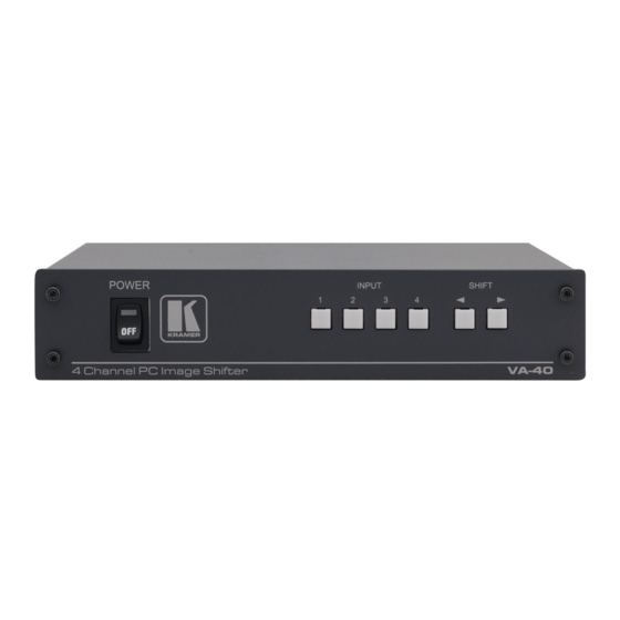
Your VA-40 4 Channel PC Image Shifter Your VA-40 4 Channel PC Image Shifter Figure 1 and Table 1 define the VA-40. Figure 1: VA-40 4 Channel PC Image Shifter Functions Table 1: VA-40 4 Channel PC Image Shifter Functions Feature... -
Page 7: Connecting The Va-40 4 Channel Pc Image Shifter
Figure 2: Connecting the VA-40 4 Channel PC Image Shifter 1 Switch OFF the power on each device before connecting it to your VA-40. After connecting your VA-40, switch on its power and then switch on the power on each device... -
Page 8: Operating The
3. Repeat for all other inputs as needed. The settings are saved in non-volatile memory 5 seconds after the last press or correction. 4. When the VA-40 is turned OFF and ON after a correction is made, the button of the last corrected input lights dimly. -
Page 9: Technical Specifications
Technical Specifications Technical Specifications The VA-40 technical specifications are shown in Table 2: Table 2: VA-40 Technical Specifications INPUTS: 4 computer graphics video on 15-pin HD (F) connectors OUTPUTS: 4 computer graphics video on 15-pin HD (F) connectors BANDWIDTH (-3dB): 1.5GHz... - Page 10 KRAMER: SIMPLE CREATIVE TECHNOLOGY...
- Page 11 For the latest information on our products and a list of Kramer distributors, visit our Web site: www.kramerelectronics.com where updates to this user manual may be found. We welcome your questions, comments and feedback. Safety Warning: Disconnect the unit from the power supply before opening/servicing.
Need help?
Do you have a question about the VA-40 and is the answer not in the manual?
Questions and answers