Table of Contents
Advertisement
Quick Links
Advertisement
Table of Contents

Related Manuals for CTX P922E


Summary of Contents for CTX P922E
-
Page 1: Service Manual
P922E SERVICE MANUAL EDITION 1 The Monitor Specialists FEB. 2003... -
Page 2: Table Of Contents
5.System Block Diagram 6. Inverter Board I/O Connection 7. IC Pin Configuration 8. Pin Assignment 9. Parts List Appendix 1. Main Board Circuit Diagram 2. Assembly Explosion Drawing TABLE OF CONTENTS Service Manual P922E PAGE 5~ 6 6~13 14~15 16~17 18~21 22~32... - Page 3 Copyright © 2002 by Chuntex Electronic Co., Ltd. The CTX SERVICE MANUAL is published by Chuntex Electronic Co., Ltd All rights reserved. No part of this manual may be used, copied, reproduced, or transmitted in any form or by any means for any purpose without the express written permission of the publisher.
-
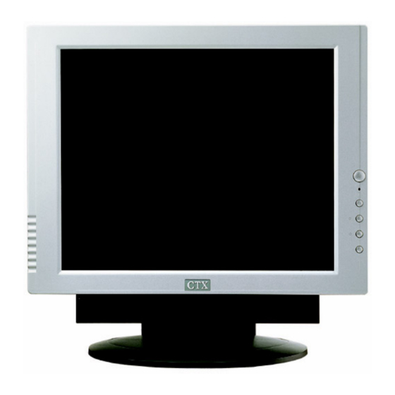
Page 4: Scope
Left side Dial volume control ISO/FDIS 13406-2 Class Ⅱ Tilt (in front bezel) and Swivel (in base) adjustable. Cable wire arrange box The differential features of the 2 models of P922E are listed in the following table Model project Feature... -
Page 5: Input Requirements
Separate horizontal & vertical sync (3.3V & 5V) Low level 0.8 V maximum High level 2.0 V minimum Positive or negative polarity a. Detachable Mini D-sub 15 pin male in two ends signal cable. Service Manual P922E ≦ ≦ ≦ ≦ ≦ 9W ≦ 5W... -
Page 6: Audio Input
G Return Pin 8 B Return DVI-D V.1 TMDS 165MHz 1-Channel signal cable b. A female DVI-D connector in monitor side. DVI-D 1-Channel Pin Assignment Signal Assignment 9 T.M.D.S Data 1- 10 T.M.D.S Data 1+ 11 T.M.D.S Data 1 Shield... -
Page 7: Electrical Characteristics
Note 5 : Fault Cluster : Two or more Pixels/Sub-pixels with faults within 5 * 5 block of pixels. 3.2 Modes and Timing Compability The monitor shall support an internal scaler to enable the monitor to display lower resolution video modes. The scaler shall convert all lower resolution modes up to 1280x1024. - Page 8 0.203 0.593 14.272 13.238 13.333 16.663 13.329 0.106 0.050 0.044 0.513 0.466 0.474 13.599 12.795 12.8 0.054 0.017 0.015 VGA Support Mode Service Manual P922E VESA VESA VESA 37.879 48.077 46.875 60.317 72.188 75.000 49.5 26.4 20.8 21.333 1.616 1.28 3.232...
- Page 9 3.5.1 The USB 2.0 module provided for 4 down-stream ports and 1 up-stream port. 3.5.2 The USB 2.0 module can detect the status of computer (USB V 30KHz to 92KHz 30KHz to 66KHz 59Hz to 85Hz 59Hz to 61Hz Service Manual P922E power) to save power.
-
Page 10: Audio Function
5V±5% (> 4.75V, < 5.25V) 0.6 to 1.25A ( 0.9A typ.) (The USB High speed(480Mbps), full speed(12Mbps) low speed(1.5Mbps) 1Vrms, 2.828Vpp(typ.) 7.8Vpp, No distortion(Input level :3.76Vpp max. volume) 1W * 2 (10% THD,1KHz) ± 3dB : 330 ~ 20KHz P922E... - Page 11 3.8 ESC ,▽ , △ , ,Signal source See Table 2. P922E OSD Control Map Press “△ ” to pop up ;then press “△ ” or “▽ ” to adjust Contrast up or down. Press “▽ ” to pop up ;then press “△ ” or “▽ ” to adjust Brightness up or down.
- Page 12 Table 2 P922E OSD Control Map 1. VGA-D15 input Level 1 Detect Adj. Brightness Detect Adj. Contrast Detect Adj. Audio Mute Auto Tune Color Main Menu Auto Tune Image Position Language Reset Source Level 2 Level 3 Adjustment Scale 9300∘ K 6500∘...
- Page 13 OSD Position Center English (select) German (select) French (select) Spanish (select) Italiano (select) 中文 (option) Yes/No DVI/VGA (select) Service Manual P922E Level 4 Adjustment Scale Adjustment Scale Adjustment Scale Adjustment Scale Adjustment Scale Adjustment Scale Adjustment Scale Adjustment Scale Adjustment Scale...
- Page 14 When the signal cable is not plugged into PC or when the horizontal or vertical sync are absent and when the monitor is turned on. After 5 sec isn’t to detect H or V Sync then show “No Signal Input” 3 sec, and then show ” Power down”...
-
Page 15: Trouble Shooying
Service Manual P922E 4. TROUBLE SHOOYING VIDEO DOES NOT APPEAR... - Page 16 Service Manual P922E R.G.B is not displayed correctly...
-
Page 17: System Block Diagram
Service Manual P922E 5. SYSTEM BLOCK DIAGRAM MAIN SYSTEM... -
Page 18: Power System
Service Manual P922E POWER SYSTEM 6. INVERTER BOARD I/O CONNECTIONS... -
Page 19: Ic Pin Configuration
Service Manual P922E 7. IC Pin Configuration... - Page 20 Service Manual P922E...
- Page 21 Service Manual P922E...
- Page 22 Service Manual P922E...
-
Page 23: Pin Assignment
Service Manual P922E 8. PIN ASSIGNMENT MAIN/BOARD... - Page 24 0.05 0.05 U12 (AT24C16N) 5.11 5.11 5.11 U13 (W981616BH-6) 0.80 3.34 0.67 0.33 0.22 3.34 1.47 1.10 1.19 3.34 Service Manual P922E 3.34 5.11 5.11 3.34 5.11 5.11 3.34 5.11 5.11 4.96 5.11 5.11 4.96 5.11 5.11 4.96 5.11 5.11 4.86...
- Page 25 3.34 0.02 2.82 2.93 3.34 0.01 2.94 U14 (W981616BH-6) 0.80 3.34 0.67 0.33 0.22 3.34 1.47 1.10 1.19 3.34 Service Manual P922E 1.66 0.01 1.60 0.02 0.70 0.02 1.37 1.31 1.18 0.92 1.09 1.26 0.84 0.90 0.99 3.34 0.92 1.25 3.34...
- Page 26 3.34 0.02 2.82 2.93 3.34 0.01 2.94 U15 (W981616BH-6) 0.80 3.34 0.67 0.33 0.22 3.34 1.47 1.10 1.19 3.34 Service Manual P922E 1.66 0.01 1.60 0.02 0.70 0.02 1.37 1.31 1.18 0.92 1.09 1.26 0.84 0.90 0.99 3.34 0.92 1.25 3.34...
- Page 27 2.82 2.93 3.34 0.01 2.94 U16 (THC63LVDM83A) 2.42 0.95 2.06 0.04 2.42 1.12 1.45 0.01 2.39 1.63 0.69 0.01 Service Manual P922E 1.66 0.01 1.60 0.02 0.70 0.02 1.37 1.31 1.18 0.92 1.09 1.26 0.84 0.90 0.99 3.34 0.92 1.25 3.34...
- Page 28 1.21 1.30 1.25 3.33 1.21 1.30 1.25 3.33 1.21 1.30 1.24 U16 (THC63LVDM83A) 1.90 2.41 0.83 2.41 0.15 2.38 Service Manual P922E 2.42 0.51 0.10 2.42 0.48 0.45 2.39 1.55 1.48 3.32 2.42 3.32 2.42 3.32 2.39 1.22 1.29 1.24 1.22...
- Page 29 1.31 3.33 1.31 3.33 1.31 U17 (THC63LVDM83A) 3.33 1.21 1.30 1.25 3.33 1.21 1.30 1.25 3.33 1.21 1.30 1.24 Service Manual P922E 2.42 3.33 2.42 2.42 3.33 2.42 2.39 3.33 2.39 2.42 0.51 0.10 2.42 0.48 0.45 2.39 1.55 1.48 3.32...
- Page 30 0.11 0.11 U18 (W78E65) 1.65 5.11 5.11 0.60 5.11 1.65 5.11 5.11 0.60 5.11 1.65 5.11 5.11 0.60 5.11 Service Manual P922E 2.38 2.41 2.39 5.11 5.11 5.11 5.11 5.11 5.11 0.02 0.02 2.17 0.02 0.02 2.17 0.02 0.02 2.17 2.77...
- Page 31 1.24 1.89 1.25 1.24 1.89 1.25 1.24 1.89 U601 (TL145ACNSR) 1.65 1.79 1.25 1.65 1.79 1.25 1.65 1.79 1.25 Service Manual P922E 0.58 3.42 3.60 0.41 3.52 0.48 5.11 5.11 5.11 1.71 9.02 1.71 9.02 1.71 9.02 1.25 0.19 2.49 1.25...
- Page 32 U702 (TL5001A) 0.07 0.07 0.07 U801(SI8050JD) 5.02 2.41 5.02 2.41 5.02 2.41 U802 (TDA7053A) 2.40 6.84 2.40 6.84 2.40 6.84 Service Manual P922E 5.15 5.15 5.15 5.15 5.15 5.15 5.15 5.15 5.15 3.39 3.39 3.39 3.39 3.39 3.39 3.39 3.39 3.39 U703(IRF9Z34N) 12.01...
- Page 33 9.72 0.68 9.72 9.70 0.68 9.71 9.68 Q612 (MMBT3906LT1) 0.03 8.64 8.53 0.03 8.64 8.53 0.03 8.64 8.53 Service Manual P922E 3.52 3.52 3.52 Q4 (2N3904) 0.04 0.75 0.04 0.75 0.04 0.75 Q9 (2N3904) 4.28 0.11 4.28 0.11 4.28 0.11 Q603 (BC817-25) 9.74...
- Page 34 12.05 13.14 12.05 12.05 13.14 12.05 12.05 Q707 (2N3904) 0.05 10.10 0.05 10.10 0.05 10.10 0.11 0.11 13.14 Service Manual P922E Q702 (2N3904) 9.42 11.82 9.42 9.42 11.82 9.42 9.42 11.82 9.42 Q705 (2N3904) 12.05 12.05 12.05 12.05 12.05 12.05 12.05...
-
Page 35: Parts List
SUB-Z ASSY ADAPTER CARTON 570*278*532 HOLDER (R) HOLDER (L) LABEL CARTON (XC1920-D01) LABEL CARTON (XC1920-D10) LABEL CARTON (CIRCLE-BLUE) LABEL CARTON (ISO134062-II) CABLE SIGNAL 15D-15D 180CM CABLE SIGNAL DVI-D 18P 180CM SUB-Z SPEAK(L) WITH WIRE(WHITE) SUB-Z SPEAK(R) WITH WIRE(RED) Service Manual P922E...
Need help?
Do you have a question about the P922E and is the answer not in the manual?
Questions and answers