
Related Manuals for CTX EX951F


Summary of Contents for CTX EX951F
-
Page 1: Service Manual
SERVICE MANUAL COLOR MONITOR P993Z Series EX951F P/N : P993Z-3-00-A Date : Jun-02-03 Version : A00... - Page 2 THESE DOCUMENTS ARE FOR REPAIR SERVICE INFORMATION ONLY. EVERY REASONABLE EFFORT HAS BEEN MADE TO ENSURE THE ACCURACY OF THIS MANUAL; WE CANNOT GUARANTEE THE ACCURACY OF THIS INFORMATION AFTER THE DATE OF PUBLICATION AND DISCLAIMS LIABILITY FOR CHANGES, ERRORS OR OMISSIONS, MANUFACTURE DATE : Jun.
-
Page 3: Table Of Contents
PAGE SPECIFICATIONS ... PRECAUTION AND NOTICES ... 2-1 SAFETY PRECAUTIONS ... 2-2 PRODUCT SAFETY NOTICE ... 2-3 SERVICE NOTES ... 2-4 HIGH VOLTAGE WARNING ... OPERATING INSTRUCTIONS ... ADJUSTMENT ... 4-1 ADJUSTMENT CONDITIONS AND PRECAUTIONS ... 4-2 MAIN ADJUSTMENTS ... 4-3 ADJUSTMENT METHOD ... -
Page 4: Specifications
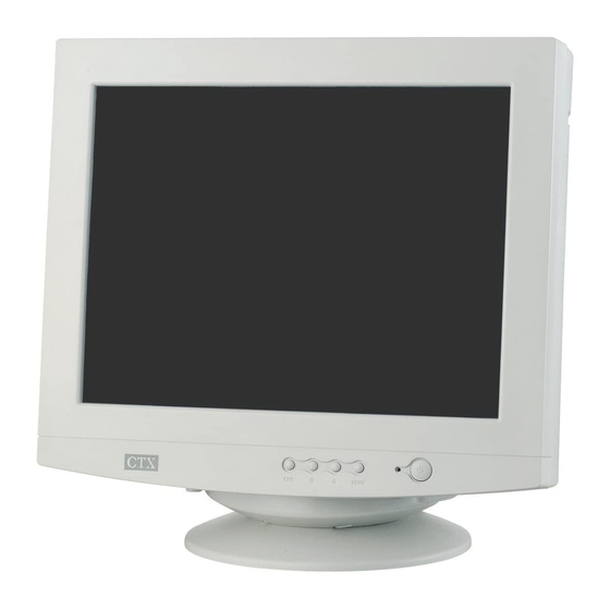
1. SPECIFICATIONS FOR 9Klr SERIES COLOR MONITOR CRT : 46CM(19") 90 Deflection, 29mm Neck, flat 0.25mm Dot Pitch, Non-Glare Screen Viewable image Size: 45.7CM (18") diagonal Display Color: Unlimited Colors External Controls: Power On/Off, OSD key, Function knob: Contrast, Brightness, H-Size, H-Center, V-Size, V-Center, ZOOM, Pincushion, Trapezoid, Pin-Balance, Parallelogram, Rotation, Moire Reduce, Recall, Degaussing, Color Temperature, Volume. - Page 5 0°C to 40°C Ambient 13. Humidity : 10% to 85% Relative, Non-Condensing Weight: 20.0 Kg (Net), 23.6Kg (Gross) for 9Klr • Dimensions Monitor: Carton: 575(W) × 526(H) × 655(D) mm Monitor: 446(W) × 436(H) ×455 (D) mm for 9Klr 16. External Connection : 15 Pin D-type Connector AC Power Cord 17.
-
Page 6: Precaution And Notices
SAFETY PRECAUTIONS 1. Observe all caution and safety related notes located inside the display cabinet. 2. Operation of the display with the cover removed, may cause a serious shock hazard from the display power supply. Work on the display should not be attempted by anyone who is not thoroughly familiar with precautions necessary when working on high voltage equipment. -
Page 7: High Voltage Warning
HIGH VOLTAGE WARNING Operation of monitor outside of cabinet or with back removed may cause a serious shock hazard. Work on this model should only be performed by those who are thoroughly familiar with precautions necessary when working on high voltage equipment. -
Page 8: Operating Instructions
With proper signals feed to the display, a pattern or data should appear on the screen, adjust the brightness and contrast to the most pleasing display. This monitor has power saving function following the VESA DPMS. Be sure to connect the signal cable to the PC. -
Page 9: Adjustment
4-1 ADJUSTMENT CONDITIONS AND PRECAUTIONS Approximately 30 minutes should be allowed for warm up before proceeding. Adjustments should be undertaken only on those necessary elements since most of them have been carefully preset at the factory. 4-2 MAIN ADJUSTMENTS FUNCTION B + ADJ SCREEN ADJ FOCUS ADJ... -
Page 10: Factory Preset
H: 68.8KHz H: 36.51kHz CONTRAST BRIGHTNESS H-CENTER H-SIZE V-CENTER V-SIZE ZOOM TOP COMER BOTTOM COMER PINCUSHION TRAPEZOID PIN-BALANCE PARALLELOGRAM ROTATION SUB-H-SIZE H-SIZE-PHASE FACTORY PRESET V: 85Hz V: 51.34Hz 9300 H-MOIRE REDUCE V-MOIRE REDUCE R-GAIN G-GAIN B-GAIN R-BIAS G-BIAS R-BIAS 9300 COLOR TEMPERATURE 6500 COLOR TEMPERATURE... - Page 11 3. White Balance, Luminance adjustment: A. Bias (Low Luminance) adjustment: (a) Set mode 5 1024 x 768 Fh: 68.7KHz full white pattern. (b) To make the adjustment condition is under the Factory preset window. Same as step 2-C. (c) Warm up more than 30 minutes. (d) Brightness set to maximum.
-
Page 12: Circuit Description
SYNC input, Pin33/Pin34 will output the same signal as input sync signal without delay, and the polarity are setting in the positive. When no signal input, the Pin33 will output a 61HZ V-SYNC free run signal. The Pin34 will output a 62.5KHz H-SYNC free run signal. for the monitor testing use. Purity Magnets... -
Page 13: Deflection Circuit
On Screen Display Controller The IC804 is designed for display the built-in characters or fonts onto monitor screen. The display operation is by transforming data and control information from micro controller to RAM through a serial data interface. Pin 2 is used to control the internal oscillator frequency by DC voltage input from external low pass filter (R830, C811, R833) and filter (R126, C115) is used to regulate the appropriate bias current for internal oscillator the resonate at specific dot frequency. -
Page 14: Transistor & Diode Circuit
5-3 TRANSISTOR & DIODE CIRCUIT LOCATION FUNCTION AL DESCRIPTION D101 For C102 Discharge D405 Speed up for Q403 D406 Supply a bias for D408 D408 Damping Diode and Modulation Diode D414~ D416,D418 Buffer Diode for Q412, Q417, Q418, Q420 Q401 B+ Mute Control Q402 Horizontal Driver... -
Page 15: Trouble Shooting Chart
6.TROUBLE SHOOTING CHART 6-1 NO RASTER, CRT RELATIVE CIRCUIT PROBLEMS CHECK MAIN PCB POWER SUPPLY CHECK MAIN PCB POWER SUPPLY 137.5V,14.5V,80V 60.5V, 14.5V, 80V CHECK THE HIGE VOLTAGE CHECK THE HIGE VOLTAGE OF CRT ABOUT 25.5~27.5KV OF CRT ABOUT 25.5 ~ 26.5KV 26.5~27.5KV CHECK THE VOLTAGE OF CRT HEATER ABOUT 6.3V... - Page 16 2.ABNORMAL VIDEO LEVEL ON SCREEN CHECK THE VOLTAGE OF IC801 7,15.18,21 ABOUT 12V PIN 6, 9, 22 ABOUT 12V CHECK THE SIGNAL INPUT OF R.G.B. ABOUT 0.7Vpp CHECK IC801 PIN 15 CLAMP PULSE PIN 16 BLANK PULSE CHECK THE VIDEO OUTPUT OF IC801 16,19,22 PIN 18, 20, 23 ABOUT 4Vpp, CONTRAST SET MAX.
-
Page 17: Abnormal Display
6-2 ABNORMAL DISPLAY 1.NO SIGNAL ON SCREEN CHECK VIDEO IC801 VCC ABOUT 12V CHECK THE OUTPUT VOLTAGE OF IC801 PIN 18, 20, 23 ABOUT 3Vpp 16,19,22 CHECK THE B+ VOLTAGE OF VIDEO PCB ABOUT 80V CHECK THE VOLTAGE OF CRT CATHODE ABOUT 40Vpp CHECK THE VOLTAGE OF FBT SCREEN ABOUT 400V TO 700V... -
Page 18: No Blanking
CHECK THE RELATIVE CIRCUIT OF BLANKING CHECK IC801 PIN 16 ON VIDEO PCB, CHECK G1 RELATIVE CIRCUIT Q705, R718, C707 ON MAIN PCB 6-4 HOR./OSC/DEF/HV CIRCUIT FAULT 1. NO RASTER (DISCONNECT WITH SIGNAL CABLE) CHECK IC401 PIN 16 ABOUT 11.5VDC CHECK IC401 PIN 10 ABOUT 11.5 VDC CHECK IC401 PIN 17 WAVE CHECK IC401 PIN 8 WAVE FORM... -
Page 19: Abnormal Horizontal Deflection
6-5 ABNORMAL HORIZONTAL DEFLECTION 1. ABNORMAL HORIZONTAL WIDTH OF VIDEO READJUST H-WIDTH FUNCTION CHECK FBT B+ VOLTAGE ABOUT 60.5V AT FH=31KHz 137V CHECK THE HV OF CRT ABOUT 26KV 2. ABNORMAL HORIZONTAL RASTER CENTER CHECK T903, D926, D927, R964, R968 P403 AND JUMPER 3. -
Page 20: Abnormal Vertical Scanning
6-6 ABNORMAL VERTICAL SCANNING 1. ABNORMAL VERTICAL SIZE READJUST V-SIZE FUNCTION READJUST V-SIZE FUNCTION VALUE VALUE CHECK THE IC601 PIN 6 CHECK THE IC601 PIN 7 ABOUT 40V ABOUT 12V CHECK VERT. OSC CIRCUIT CHECK IC601 PIN 6 OUTPUT ABOUT CHECK IC601 PIN 6 OUTPUT 38Vpp ABOUT 45Vpp... -
Page 21: Poor Focus
READJUST FOCUS CONTROL 6-9 NO SOUND (FOR AUDIO MODEL ONLY) ADJUST VOLUME CONTROL ENSURE THE SOUND SOURCE IS POWER ON ENSURE THE SOURCE CABLE CONNECTION 6-8 POOR FOCUS CHECK FOCUS CONTROL UNIT, FOCUS LEAD WIRE, CRT SOCKET & CRT CHECK IC501 PIN 14 ABOUT 14V CHECK IC501 SPEAKER FAILURE... -
Page 22: Power Supply Trouble Shooting Chart
6-10 POWER SUPPLY TROUBLE SHOOTING CHART BEFORE CHECK SW.REG. PLEASE REFER TO THE POWER SUPPLY BLOCK DIAGRAM POWER SUPPLY OUTPUT: (A) BEAD SET CHECK AC LINE VOLT 120V OR 220V CHECK F901, SW901 CHECK LINE RECTIFIED & SMOOTHED VOLT CHECK BRIDGE RECTIFIED CIRCUIT CHECK START CHECK START C.K.T... -
Page 23: Mechanical Of Cabinet Front Dis-Assembly
7. MECHANICAL OF CABINET FRONT DIS-ASSEMBLY... -
Page 24: Parts List Of Cabinet
SUPPORT BASE BACK COVER SWIVEL FRONT PANEL CRT WARNING LABEL CARTON LABEL TCO99 LABEL WINDOWXP LABEL SERIAL LABEL FOR MONITOR BLUE DOT ID LABEL TCO99 CARD WARRANTY BOOKLET WARRANTY CARD MANUAL CARTON PE BAG FOR CARD PE BAG FOR MANUAL... - Page 25 85A6028507 89A404A18N YH 95A8013 2 B1A1035 10128 Q1A 340 16128 750A1697 77 BK W33A4174 A5 T 95A2070520 CMP993Z5CT Location AMP993Z5CT CRP993Z5CT 1A 421 4128 9A 203 9 11A6033 1 15A5640 1 A 40A 581 26702 40A 581624 2B 50A 502 1 71A 100 9 89A174B8DM GG B1A1040 10128...
- Page 26 C483 67A 309470 3 C607 67A 305221 6 C608 67A 305102 4 C612 67A 305102 3 C703 67A 305109 15 C713 67A305W10012K C716 67A 305220 7T C719 64A178J754 1A C900 63A 107224 5S C901 63A107K474 U C906 63A210J4733CC C907 67A 3022115D CMP993Z5CT Location C912...
- Page 27 ★ IC101 56A1125107 X IC102 56A1133513 ★ IC401 56A 552 5 ★ IC902 56A 139 3 ★ IC906 56A 139 3 J003 71A 55 19 T J059 71A 55 19 T J10-13 73A 5410010T ★ L401 73A 147121 T L402 73A 253103 SP ★...
- Page 28 T901 80A 793 1 LS T902 73A 174 18 L T903 79A 167120 H T904 73A 253135 L TP701 9A 211 2 TP702 9A 211 2 VR701 75A 335223 VR702 75A 335204 VR703 75A 335104 VR902 75A 334303 ★ X101 93A 22 43 AMP993Z5CT Location...
- Page 29 ★ C417 64A701J1540AT ★ C420 64A178J223 1T C421 65A 444332 5T ★ C422 65A 444101 5T ★ C423 65A 450104 7T ★ C424 67A 309100 7T ★ C426 65A 444101 5T ★ C427 67A 70229 9T ★ C433 64A701J2240AT ★ C434 67A 309109 7T ★...
- Page 30 ★ C701 67A 309100 7T ★ C702 65A 1K471 2T6052 ★ C704 67A 309100 7T ★ C705 65A 444103 5T ★ C707 64A176J104 2T ★ C708 67A 309100 7T C710 67A 70478 9T ★ C711 65A 444102 5T ★ C714 64A178J153 1T ★...
- Page 31 ★ D405 93A1002 1P52T ★ D406 93A1060 652T ★ D407 93A 64 1152T ★ D409 93A 64 1152T ★ D410 93A 6450152T ★ D411 93A 64 1152T D412 93A1040 252T ★ D413 93A 64 1152T ★ D414 93A 6021P52T ★ D415 93A 6021P52T ★...
- Page 32 FB907 95A 90 23 ★ IC904 56A 158 1 T J001 95A 90 23 J002 95A 90 23 J005 95A 90 23 J006 95A 90 23 J007 95A 90 23 J008 95A 90 23 J009 95A 90 23 J010 61A175L22852T J011 95A 90 23 J012...
- Page 33 J053 95A 90 23 J054 95A 90 23 J055 95A 90 23 J056 95A 90 23 J057 95A 90 23 J060 95A 90 23 J062 95A 90 23 J063 95A 90 23 J064 95A 90 23 J065 95A 90 23 J067 95A 90 23 J068...
- Page 34 J111 95A 90 23 J112 95A 90 23 J113 95A 90 23 J114 95A 90 23 J116 95A 90 23 J117 95A 90 23 J118 95A 90 23 J119 95A 90 23 J120 95A 90 23 J121 95A 90 23 J122 95A 90 23 J123...
- Page 35 ★ Q419 57A 419 P T ★ Q427 57A 721 1 T ★ Q428 57A 419 P T ★ Q429 57A 419 P T Q450 57A 420 P T ★ Q701 57A 419 P T ★ Q702 57A 420 P T ★...
- Page 36 R138A 61A 60247252T R139 61A 60222252T R140 61A 60222252T R141A 61A 60247252T R149 61A 60247252T R151 61A 60247252T R152 61A 60247252T R153 61A 60247252T R157 61A 60210252T R219 61A 60236352T R221 61A 60215352T R222 61A 60210252T R223 61A 60222252T R224 61A 17251052T AMP993Z5CT Location...
- Page 37 R442 61A 60247252T R443 61A 21013252T R444 61A 60222252T R445 61A 60210352T R446 61A 17215452T R447 61A 60210252T R448 61A 60256352T R449 61A 60247252T R450 61A 17247452T R452 61A 21056352T R453 61A 60222252T R455 61A 60233252T R458 61A 60230352T R459 61A 60210252T AMP993Z5CT Location...
- Page 38 R701 61A 60210352T ★ R702 61A 60291352T ★ R703 61A 60262252T R704 61A 17218252T R705 61A 60210152T R706 61A 60210052T R707 61A 60210352T ★ R708 61A 60282352T R709 61A 60210352T ★ R710 61A175L15052T R711 61A 60247252T R713 61A 60210252T R714 61A 60210252T R715 95A 90 23...
- Page 39 R915 61A 60212252T R916 61A 17230252T R917 61A 17213452T ★ R918 61A175L75352T R919 61A 21022252T ★ R921 61A175L56352T R922 61A214Y10552T R923 61A 60210252T R924 61A 60210352T ★ R925 61A 60268152T R929 61A 17218252T R938 61A 17213452T R939 61A 17227452T R940 61A 17220452T AMP993Z5CT Location...
- Page 40 705A792XR56 01 C829 67A 305470 9 C874 65A 2M103 3B6921 D863 93A 6021P52T FB802 53A 40 8 FB803 53A 40 8 FB804 53A 40 8 FB806 71A 55 9 T FB808 71A 5519R FB810 71A 55 21 FB852 71A 55 19 T 9A 203 8 IC801 56A 539 5...
- Page 41 C822 64A178J104 0T C823 64A178J104 0T C824 64A178J104 0T C825 65A 44210013T C826 65A 1K101 5T6052 C828 65A 550103 4T C831 65A 550103 4T C832 67A 309109 9T C833 65A 450104 7T C840 65A 550103 4T C842 65A 550103 4T C851 67A 309470 7T C852...
- Page 42 FB807 95A 90 23 FB809 71A 55 9 T FB851 71A 55 9 T J801 95A 90 23 J802 95A 90 23 J803 95A 90 23 J804 95A 90 23 J805 95A 90 23 J806 95A 90 23 J807 95A 90 23 J808 95A 90 23 J809...
- Page 43 R830 61A 60256252T R831 61A 60256252T R832 61A 60275252T R834 61A 60210252T R835 61A 60210252T R836 61A 60210252T R837 61A 60210252T R839 61A 60222252T R847 61A 60222052T R848 61A175L15952T R854 61A 17222052T R855 61A 17222052T R856 61A 17222052T R857 61A 17210552T R858 61A 17210552T R859...
- Page 44 705A993SC56 01 Location 5A 71 1 32A3028 8 90A 376 1 M1A1730 10128 ★ IC601 56A 574 1 705A993SC57 01 Location 5A 71 1 5A 71 1 90A 363527 P M1A1130 8128 M1A1730 8128 M1A1730 10128 M1A1730 12128 D408 93A 220505 705A993SC57 01 Location ★...
- Page 45 P701 33A3803 3 R618 61A 208109 64 ★ T402 79AS793 1 TP498 95A201M 50172 WAFER EH-E MOFR 1 OHM +-5% 1W FBT BY SAMPO WIRE...
-
Page 46: Ic Block Diagrams
9. IC BLOCK DIAGRAM IC101:NT68F65U IC102:24C08 IC901:STR-G9656D... - Page 47 IC401:UPC1888ECT...
- Page 48 IC804 NT6828-00046 IC801: LM 1269NA...
- Page 49 IC803:LM2480NA IC904:PC431CLP IC903:L7812CV...
- Page 50 IC601 TDA9302H IC802 LM2467...
-
Page 51: Main Pcb Layout
10-1 MAIN PCB LAYOUT (SW103) SW104 SW101 SW105 SW103 R105 J091 LED1 LED4 LED2 LED3 D929 C112 Q205 J016 J135 J002 J129 J127 R141A R139 R123A Q101 R153 R119A R112 R138A R152 R130 ZD104 R129 R151 C111 J133 R124 C105 J134 R125 C104... - Page 52 10-2 CRT BOARD LAYOUT C843 C864 FB807 IC802 C828 J808 L851 FB808 C817 R857 D850 J813 R854 D851 D858 C844 R874 R848 GND4 C842 FB806 R879 GND5 R818 R826 R827 R816 R817 C815 (R817) J804 D808 ZD801 D807 R811 C810 C878 R812 C852...
-
Page 53: Schematic Diagram
P202 CMPC-P993-3 715A1027-* H802B ISDA R227 IC101B WT62P1 R119 ISCL R157 R116 R229 R153B IC101A C110 NT6865 1000 D106 JUMPER MUTE V-SYNC Q207 R215 R225 R226 C206 V-OUT H-SYNC C204 C101 C102 R228 100UF SUSPEND R143 H-SIZE C115 D204 P106 RESET D108 R122...
Need help?
Do you have a question about the EX951F and is the answer not in the manual?
Questions and answers