Table of Contents
Advertisement
Quick Links
Advertisement
Table of Contents

Related Manuals for Tescom CL115D Series


Summary of Contents for Tescom CL115D Series
- Page 1 CL115D USER MANUAL...
- Page 2 INTRODUCTION Thank you for choosing this product Our company is specialized in the design, development and production of Uninterruptible Power supplies (UPS) The UPS described in this manual is a high-quality product, built to guarantee the best performance. This manual contains detailed instructions on how to use and install the product. For information on how to use your equipment to its full potential, this manual should be kept close at hand beside the UPS and PLEASE READ BEFORE STARTING TO WORK ON IT! Copying all or any part of this manual is strictly prohibited unless due authorization has been granted by the...
-
Page 3: Table Of Contents
CONTENTS I. GENERAL DESCRIPTION ........................1 CL115D SERIES UPS .......................... 1 Cooling ..............................3 Block diagram of the UPS ........................3 SAFETY WARNINGS .......................... 4 Front view of the UPS ........................... 5 Rear view of the UPS ..........................5 VIEW OF THE CONTROL PANEL ......................6 II. - Page 4 AGKK9530 01/2011...
-
Page 5: General Description
I. GENERAL DESCRIPTION CL115D SERIES UPS To choose the CL115D series as your equipment protector was a wise investment. It includes many features to protect your critical equipments. Power ranges according to models Model Output power CL115D 15000 VA / 10500 Watt This unit supplies continuous power to critical loads from AC input or DC battery power. - Page 6 • INPUT IGBT rectifier type input PFC correction PI controlled PFC circuit Fuse protected input Adjustable mains failure limit Adjustable mains high limit (switching tobattery option) • BYPASS Static bypass system Split bypass input (OPTIONAL) Voltage adaptive load transfer system Adjustable bypass input voltage limits Adjustable frequency synchronization band Maintenance bypass switch (OPTIONAL)
-
Page 7: Cooling
Cooling A cooling fan is installed on the rear panel of the UPS as air outlet (see back view nr:12 item of the UPS) ,and another cooling fan is installed on the front side of the UPS as air inlet (see front view nr:1 item of the UPS). A temperature sensor on the controller board, measures the ambient temperature inside the cabinet and, if the temperature is higher than a predetermined value,UPS produces an overtemperature alarm. -
Page 8: Safety Warnings
SAFETY WARNINGS IMPORTANT NOTICES 1. This manual must be carefully read before applying any power to the UPS unit. 2. All warnings in the manual should be adhered to. 3. All operating instructions should be followed. 4. The unit should be supplied by a grounded outlet. Do not operate the unit without ground source. 5. -
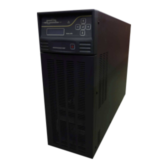
Page 9: Front View Of The Ups
Front view of the UPS 1) Cooling inlet of the UPS 2) Control panel 3) Power on/off button Rear view of the UPS 4) Emergency Stop 5) SNMP Socket 6) RS232 communication port 7) Cooling outlet of the UPS 8) Output switch/fuse (S1) 9) Input switch/fuse (S2) 10) Battery switch/fuse (S3) 11) Maintenance bypass switch (SW5) -
Page 10: View Of The Control Panel
VIEW OF THE CONTROL PANEL ENTER button Alarm indicator lamp Menu up navigation button Increases the current data Menu down navigation button Decreases the current data Load on bypass lamp Load on UPS lamp Alphanumeric LCD panel function 1. Line : menu items and measured parameters 2. -
Page 11: Preparation For Installation
PREPARATION FOR INSTALLATION PRELIMINARY INFORMATION Model CL115D Nominal output power 15000 VA / 10500 Watt Operating temperature 0 – 40 C Non operating temper. -10 to + 50 C Max.relative humidity 90% (non-condensing) during operation Max.installation altitude 2000 m at nominal power rating Dimensions (WxDxH) 215 x 775 x 585 mm Weight (kgs) -
Page 12: Installing The Ups
INSTALLING THE UPS When installing the equipment the following points should be considered: • The air outlet and inlet of the UPS is on the rear and front respectively, because of this do not prevent air ventilation from the rear and front side. •... -
Page 13: Cable Sizes
Battery CONNECTIONS CL115D Series UPS run only on 1-Phase AC power supplies with a NEUTRAL line. The UPS unit must be grounded in accordance with electrical regulations Before making power connections to the unit, ensure that the incoming power sources are de-energized and insulated. -
Page 14: Rs232 Connector
Function Description AUX1 RELAY (OPTIONAL) Function selectable (NO-NC programmable) AUX2 RELAY (OPTIONAL) Function selectable (NO-NC programmable) BYPASS RELAY(OPTIONAL) Standard connection to RS232 connector (NO-NC programmable) DIGITAL INPUT OPTIONAL (Reserved for special applications) REPO INPUT Standard Remote Emergency Power Off input (NO-NC programmable) Bypass relay is standard. -
Page 15: External Repo Button
EXTERNAL REPO BUTTON REPO input is the screw terminal pair at the rear next to the RS232 connector. The function of the REPO input can be programmable from ADJUST MENU. The selectable options are: Function Description NO contact If REPO input terminals are shorted emergency power off will applied NC contact If REPO input terminals are opened emergency power off will applied This isolated input is used to turn off the UPS remotely in case of emergency. -
Page 16: Protective Earth
PROTECTIVE EARTH The protective earth cable must be connected to the earth connection terminal and bonded to each cabinets in the system and also the earthing and neutral bonding arrangements should be in accordance with the local laws. Proper grounding considerably reduces problems in systems caused by electromagnetic interference. ATTENTION!!! Failure to follow adequate earthing procedures can result in electric shock hazard to people or risk of fire. -
Page 17: Operation
III. OPERATION DESCRIPTION The purpose of the UPS is to provide constant power which is in predefined limits. While the input voltage is in acceptable tolerances, UPS converts the AC mains input voltage to DC voltage , then inverter stage will convert to AC output voltage again. -
Page 18: Preliminary Operations
OTHER Cabinet inside temperature high alarm (adjustable) REPO Emergency Power Off feature. PRELIMINARY OPERATIONS • Visual check of the connections Check that all the connections have been made following the information given in the “Connections” paragraph. • Check that the switch positions are as follows: Output Switch (S1) in OFF position Input Switch (S2) in OFF position Battery Switch (S3) in OFF position... -
Page 19: Switching Off The Ups From On (Normal Operation) Position
• And see the front panel lamps on • Turn on battery switch (S3) • Check that there is no alarm on front panel Switching Off The UPS From On (Normal Operation) Position • Press power button and wait until you hear an intermittent buzzer sound, at his moment the load is transferred to bypass •... -
Page 20: Front Panel
IV. FRONT PANEL DISPLAY At the center of the control panel, there is a 2 lines/16 alphanumeric characters display, which provides a detailed overview of the current status of the UPS. Directly from front panel you can control the UPS, monitor the electrical values of the inputs, output etc..and change the main settings. -
Page 21: Display Menus
DISPLAY MENUS The function of LCD panel is arranged as a 2 level menu structure. -Main menu -Sub menus STATUS MENU ____________________________________________________________ POWER OFF FAULT ! WARNING ! 015 ALARM ! WARNING ! Messages displayed by order of priority WARNING ! 600 PFC START ! INVERTER START ! STATUS NORMAL ! -
Page 22: Measures Menu
MEASURES MENU _________________________________________________________ LOAD:025% 05.0A OUT.:230V 50.0Hz BYP.:230V 50.2Hz (option) LOAD CF.: 1.4 INP.:240V 49.9Hz Use Up and Down buttons to move on submenu I/P CURR.: 18.5 A BATT:257V +0.50A BAT. TIME: - - - mn TEMP: +025 C <ENT>EXIT From this menu users can see all measured parameters of the UPS. -
Page 23: Alarms Menu
ALARMS MENU ____________________________________________________________ The most important function of the UPS is alarms menu. There is a real time clock in the UPS and the UPS records all events by their date and time. And the user can see all previous events and alarms by order of occurrance. -
Page 24: Adjust Menu
ADJUST MENU ____________________________________________________________ The submenu items of this menu and their functions are described in the service manual of the CL115D series UPS. Please refer to this document. OPTIONS MENU ____________________________________________________________ This menu contains user adjustable operating modes, options and parameters. These are as follows: LANG: ENGLISH or TURKISH This option determines the front panel language of the UPS. -
Page 25: Time Menu
RELAYS:NO or NC Dry contact relay outputs on RS232 connector and on other connectors are NC (normally closed) or NO (normally open) type OPTION DESCRIPTION Relays will be energized if the related alarm occurs Relays will be de-energized if the related alarm occurs TEMP.COMPENS:ON/OFF (Battery temperature compensation on/off option) OPTION DESCRIPTION... - Page 26 HOURMTR: 12030 Operating hour meter of the UPS (not resettable) NEXTSERVC: 1000 This number indicates the remaining time until the next scheduled service in terms of hours. The UPS creates a warning if this number is zero or negative. This value can be set by service personnal when service password is entered.
-
Page 27: Command Menu
COMMAND MENU __________________________________________________________ From this menu user can apply immediate commands to the UPS. SOUND.: ON <ENT> BYPASS <ENT>CANCEL SHUT Use Up and Down buttons to move on submenu <ENT>LAMP TEST <ENT>EXIT SOUND: ON or OFF Each pressing to ENTER button will change the alarm buzzer enable(on) or disable(off) status. <ENT>... - Page 28 Message class A51 MAINTENANCE Alarm A52 MANU.BYPASS Alarm A63 INV.FAILURE Alarm A65 MAINS HIGH Warning A66 +DC BUS TOL Alarm A72 AV.BATT.HIGH Warning A76 –DC BUS TOL Alarm A77 BYP. FREQ. BAD Warning A7 BATTERY LOW warning Battery voltage is less than the minimum allowed warning value. During this alarm inverter continues its operation.
-
Page 29: Status Codes
A23 SERVICE TIME The service time indicator was adjusted during the last service and UPS working-hour has reached this value . This warning means that the routine maintenance time is now. The maintenance includes dust cleaning ,battery maintenance, etc. A42 BATTERY TEST UPS is performing battery test A48 BYPASS UPS has transferred the load to bypass supply for some reason. -
Page 30: Fault Codes
Fault codes The following table shows fault codes and messages of the UPS. If any one of these fault codes is shown at the second line of LCD panel, the UPS operation has already been blocked. To restart the UPS, from SERVICE menu go to <ENT>... -
Page 31: Adjust Menu
Split bypass input is the secondary AC input to the UPS. This input is used for transferring the load to bypass. As a default, there is no split bypass input on a standard CL115D series UPS. But during production in the factory, it is possible to install a separate split bypass input to the UPS. - Page 32 IP.HIGH:BATT /MESSAGE (During mains high alarm operate from batteries or not selection) OPTION DESCRIPTION BATT During A65 mains high alarm, UPS starts operating from batteries (for protection) MESSAGE During A65 mains high alarm, UPS shows only message In some cases, if the mains input voltage is high (adjustable level), it is better to operate on batteries to prevent any possible damage to the UPS..
-
Page 33: Communication Interface And Remote Management
V. COMMUNICATION INTERFACE AND REMOTE MANAGEMENT The following information contains standard communication interface for CL100 series UPS. Additional RS485 interface for long distance communication is available as an option. The following communication interfaces are available for UPS units Possible connections to UPS unit RS232 Serial communication (Standard) RS485... - Page 34 For adjustment parameters you must type the service password from front panel, otherwise any adjustment and option selection parameter will be refused. Optional SNMP adaptor The internal and external type adaptors are available for CL115D series UPS . External SNMP adaptor If external type data adaptor is used from options menu select DATA:RS232 option.
-
Page 35: Technical Specifications
VI. TECHNICAL SPECIFICATIONS CL115D MODEL Output (VA) 15000 Output (KW) 10500 Output Power Factor INPUT Number of Phases 1 phase + neutral Input Voltage 220/230/240 VAC (3 wire) Input Voltage Range 170-275V adjustable (without switching to battery power) Input Power Factor (PF) >0.99 at full load Input THDI <5% at full load... - Page 36 BATTERIES Total number of battery blocks 20 nominal (battery number selectable) Internal batteries 20x12V/12Ah Float Charge Voltage (adjustable) 272 V (for 20x12V batteries at 25 C) End of Discharge Voltage (adjustable) 192 V (for 20x12V batteries) Boost Charge Available Boost charge voltage (adjustable) 288 V (for 20x12V batteries) Battery Test Available (automatic or manual)
- Page 38 AGKK9530 06/2014...
Need help?
Do you have a question about the CL115D Series and is the answer not in the manual?
Questions and answers