Advertisement
Quick Links
http://www.delta.com.tw/industrialautomation/
Programmable Logic
DVP-SS
Instruction Sheet
1
WARNING
Please carefully read this manual thoroughly prior to use the DVP PLC.
The AC input power must be disconnected before any maintenance.
This is an OPEN-TYPE built-in PLC, and the PLC is certified to meet the safety requirements of IEC 61131-2
(UL 508) when installed in the enclosure to avoid high temperature, high humidity, exceessive vibration,
corrosive gases, liquids, airbome dust or metallic particles. Also, it is equipped with protective methods such
as some special tool or key to open the enclosure, to avoid the possible hazard to users or any damage to
the PLC.
Do not connect the AC power to any of the input/output terminals, as it might cause damage to the PLC.
Make sure that all the wiring is well conducted prior to power on. Do NOT touch terminals when power on.
Do not touch the internal circuit for at least 1 minute after the power supply is OFF.
Make sure that the PLC is properly grounded
, to avoid any electromagnetic noise.
2
INTRODUCTION
2.1 Model Explanation and Peripherals
Thank you for choosing DELTA's DVP PLC Series. The DVP-SS series provides a 14-point Main Processing Unit
and allows to expand units with 8~16 points. The maximum input/output points could be extended up to 128 points.
Since the power supply unit is independent of the main unit, and with the volume of the device being smaller, the
installation of DVP PLC is thus easier.
Nameplate Explanation
PLC Model
Input Power Supply Specification
Output Module Specification
Bar Code and Serial Number
CE
Software Version
V4.9
Model Explanation
Model
Serial Number Explanation
Version
Product Series
R: Relay
Input+Output point
T: Transistor
S TYPE
N: No Output Module
Model type
DC Power Input
S: Standard Function MPU
M: Input Point Expansion Unit
N: Output Point Expansion Unit
P: I/O Point Expansion Unit
Periphery Equipment
◎ DVPHPP Handheld Programming Panel
◎ WPLSoft (WINDOWS) Ladder Diagram Editor
◎ DVPACAB115 Cable (HPP
PLC, 1.5m)
◎ DVPACAB215 Cable (PC
PLC, 1.5m)
◎ DVPACAB230 Cable(PC
PLC/3 公尺), DVPACAB2A30 Cable(PC
◎ DVPACAB315 Cable (HPP
PC, 1.5m)
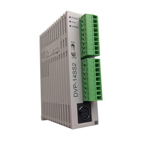
2.2 Product Profile and Outline
4
5
3.00
1
25.20
6
60.00
7
POWER
s
s
RUN
X0
ERROR
X1
14
X2
X3
RUN
X4
X5
X6
X7
STOP
C0
Y0
90.00
C1
Y1
2
C2
Y2
Y3
Y4
Y5
3
4.00
2006-05-05
1. Status indicator (Power, RUN and ERROR)
2. I/O port for program communication (RS-232)
3. DIN rail clip
4. I/O terminals
5011608703-ZSE4
5. I/O point indicator
6. Mounting hole of the extension unit
7. Nameplate
Controller
2.3 Model Numbers
◎ Standard Function MPU
Model
DVP14SS11R2
DVP14SS11T2
◎ Digital I/O Extension Unit
Model
DVP08SM11N
DVP08SN11R
DVP08SN11T
DVP08SP11R
DVP08SP11T
DVP16SP11R
DVP16SP11T
◎ Analog/temperature module extension unit
Please refer to user manuals that go with PLC.
◎ Power Supply Module
Model
DVPPS01
Production Week
DVPPS02
Production Year (2002)
Production Place (Taoyuan)
Version
Production Model
3
3.1 Function Specifications
Item
Control Method
I/O Processing Method
Execution Speed
PLC/3 公尺)
Program Language
Program Capacity
Instructions
Step Relay
Primary step point
(Latched)
General step point
General
Auxiliary
Latched
Relay
11
Special
8
10
12
Timer
Digital
9
General
13
Latched
Counter
3
High-Speed
General
Data
Latched
Register
Special
8. Extension port
9. Extension unit clip
10. DIN rail (35mm)
11. RS-485 Communication port
12. Mounting rail of the extension unit
13. DC Power input
14. RUN/STOP switch
Input/Output
Input Unit
Output Unit
Power
Point
Type
Point
Type
8
6
Relay
DC Type
24VDC
Sink or Source
8
6
Transistor
Input/Output
Input Unit
Output Unit
Power
Point
Type
Point
Type
8
0
None
0
8
Relay
0
8
Transistor
DC Type
24VDC
Sink or Source
4
4
Relay
4
4
Transistor
8
8
Relay
8
8
Transistor
Input/Output
Input Power
Output Power
100~240VAC
Output voltage: 24VDC
( 50/60Hz )
Output current (max.): 1A
100~240VAC
Output voltage: 24VDC
( 50/60Hz )
Output current (max.): 2A
STANDARD SPECIFICATIONS
Specification
Remark
Stored program, cyclic scan system
Immediate refresh command available only
Batch I/O (refresh)
with I/O of the MPU
Basic command (several μs)
Application command (10~hundredsμs)
Instructions + Ladder Diagram + SFC
Step instructions included
3792 Steps
Built-in EEPROM
Basic commands: 32 (including the STL
Application commands: 107
commands)
10 Points
S0~S9
118 Points
S10~S127
512+232 Points
M000~M511 + M768~M999
256 Points
M512~M767
280 Points
M1000~M1279
64 Points
T0~T63 (100 ms time base)
T64~T126 (10 ms time base, when M1028 is
63 Points
On)
1 Point
T127 (1 ms time base)
112 Points
C0~C111
16 Points
C112~C127
13 Points 1-Phase 20KHz, 2-Phase 5KHz
C235~C254 (all of which are latched type)
408 Points
D0 ~ D407
192 Points
D408~D599
144 Points
D1000~D1143
Item
Pointer
P
64 Points
Index Relay
E/F
2
Decimal K
16 bit: -32768~+32767
Constant
Hexadecimal H
16 bit: 0000~FFFF
Program write/read communication port: RS-232C. General function communication port:
Serial Communication Port
RS-485 (controlled by the RS command). The DELTA's inverter-specific drive commands are
included as well.
* Additional remark: Refer to the PLC Technique Application Manual for relevant special relays and data registers.
3.2 General Specifications
Model
DVPPS01
Item
100~240VA
24VDC (-15%~20%) (the counter-connection protection towards the DC input power
Power Supply Voltage
Profile Reference
C (50/60Hz)
polarity is included)
Motion Specifications
Within 5ms of the momentary power loss, the device will keep on operating
Capacity of the Power
2A / 250VAC
Supply Fuse
Power Consumption
---
Insulation Resistance
---
Above 5 MΩ (500VDC between the ground and all the I/O points)
ESD(IEC 61131-2, IEC 61000-4-2): 8KV Air Discharge
EFT(IEC 61131-2, IEC 61000-4-4): Power Line: 2KV, Digital I/O: 1KV, Analog & Communication I/O: 1KV
Noise Immunity
Damped-Oscillatory Wave: Power Line: 1KV, Digital I/O: 1KV
RS(IEC 61131-2, IEC 61000-4-3): 26MHz~1GHz, 10V/m
The diameter of the grounding wire cannot be smaller than that of terminals L and N (if numerous PLCs
Grounding
are used at the same time, make sure that each PLC is grounded respectively to the ground poles)
Ambient
For operation: 0℃~55℃ (temperature), 50~95% (humidity), the 2
Temperature/Humidity
Storage: -40℃~70℃ (temperature), 5~95% (humidity)
Vibration/Shock
International Standard Regulations: IEC1131-2, IEC 68-2-6 (TEST Fc) / IEC1131-2 & IEC 68-2-27 (TEST
Profile Reference
Immunity
Ea)
Weight (approximation)
210(g)
214(g)/208(g)
Approvals
Input Type
DC (SINK or SOURCE)
Input Current
24VDC 5mA
Off→On, above 16VDC
Motion Level
On→Off, below 14.4VDC
Responding Time
About 10ms (An adjustment range of 0~20ms could be selected through D1020 and D1021)
Output Type
Relay-R
Current Specifications
1.5A/1 point (5A/COM)
Voltage Specifications
Below 250VAC, 30VDC
Maximum Loading
75 VA (Inductive)
Responding Time
About 10 ms
4
Profile Reference
4.1 Terminal Wiring of the Standard Function MPU and the Digital I/O Extension Unit
Power Module
DVPPS01
DVPPS02
DVP-PS01
DVP-PS02
POWER
POWER
4.2 Mounting Arrangements and Wiring Notes
When installing the DVP series PLC, make sure that it is installed in an
enclosure with sufficient space (as shown diagram on the right) to its
surroundings for heat dissipation purpose.
Installation of the DIN Rail
The DVP-PLC can be secured to a cabinet by using the DIN rail. This DIN rail should be 35mm high with
a depth of 7.5mm, and when mounting the PLC on the DIN rail, be sure to use the end bracket to stop any
side-to-side motion of the PLC, which will reduce the chance of the wires being pulled loose. At the bottom
of the PLC is a small retaining clip. To secure the PLC to the DIN rail, place it onto the rail and gently
push up the clip. To remove it, pull down the retaining clip and gently pull the PLC away from the DIN rail.
Wiring
22-16AWG
Use the 22-16AWG (1.5mm) single-core bare wire or the multi-core wire for the
I/O wiring, and the specifications of the terminal are shown diagram on the left.
The twisting power of the screw for the PLC terminal is 1.95 kgf-cm (1.7 lb-in).
Be sure not to place power wires such as the input point signal wire and the
output point wire at the same conduit or to use the same multi-core wire.
< 1.5mm
Specification
Remark
P0~P63
E (=D1028), F (=D1029)
32 bit: -2147483648~+2147483647
32 bit: 00000000~FFFFFFFF
DVP14SS
DVP08SM11N
DVP08SN11R/T
DVP08SP11R/T
DVP16SP11R/T
11R2/T2
---
3.5W
1W
1.5W
1.5W
2W
nd
degree pollution.
128(g)
154(g)/146(g)
141(g)/136(g)
162(g)/154(g)
Input Point Electric Specifications
Output Point Electric Specifications
Transistor-T
55℃ 0.1A/1point, 50℃ 0.15A/1point
45℃ 0.2A/1 point, 40℃ 0.3A/1 point (2A/COM)
30VDC
90 W
9W
(Resistive)
Off→On 15us
On→Off 25us
INSTALLATION & WIRING
MPU
Digital I/O Extension Unit
DVP14SS
DVP08SM
DVP08SN
DVP08SP
DVP16SP
S / S
S / S
C 0
S / S
X 0
X 0
Y 0
X 0
X 1
X 1
Y 1
X 1
X 2
X 2
Y 2
X 2
X 3
X 3
Y 3
X 3
X 4
X 4
Y 4
X 5
X 5
Y 5
RUN
X 6
X 6
Y 6
X 7
X 7
Y 7
C 0
C 0
STOP
Y 0
Y 0
C 1
C 1
Y 1
Y 1
C 2
C 2
Y 2
Y 2
Y 3
C 3
Y 4
Y 3
Y 5
50mm or more
DVP MPU
50mm
50mm
or more
or more
50mm or more
S / S
X 0
X 1
X 2
X 3
X 4
X 5
X 6
X 7
C 0
Y 0
Y 1
Y 2
Y 3
Y 4
Y 5
Y 6
Y 7
Advertisement

Related Manuals for Delta DVP-SS


Summary of Contents for Delta DVP-SS
- Page 1 About 10ms (An adjustment range of 0~20ms could be selected through D1020 and D1021) 2.1 Model Explanation and Peripherals DVP08SP11T Transistor Output Point Electric Specifications Thank you for choosing DELTA’s DVP PLC Series. The DVP-SS series provides a 14-point Main Processing Unit Output Type Relay-R Transistor-T DVP16SP11R Relay and allows to expand units with 8~16 points.
- Page 2 Overload Capacity of the Output Terminal or the WPLSoft (the Windows version) ladder diagram editing program are all good for use with the DELTA 3. Check periodically whether the wiring and terminals are tightened and conducted properly.