Table of Contents
Advertisement
Quick Links
SYSTEM AIR CONDITIONER
SYSTEM AIR CONDITIONER
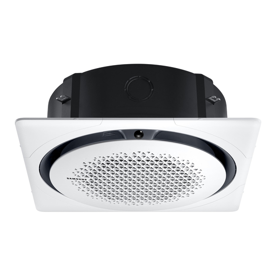
CIRCULAR CASSETTE SERIES
INDOOR UNIT
AC018KN4DCH
AC024KN4DCH
AC030KN4DCH
AC036KN4DCH
AC042KN4DCH
AC048KN4DCH
CONTENTS
1. Precautions
2. Product Specifications
3. Disassembly and Reassembly
4. Troubleshooting
5. PCB Diagram
6. Wiring Diagram
7. Reference Sheet
OUTDOOR UNIT
AC018JX4DCH
AC024JX4DCH
AC030JX4DCH
AC036JX4DCH
AC042JX4DCH
AC048JX4DCH
Advertisement
Table of Contents

Related Manuals for Samsung AC018KN4DCH


Summary of Contents for Samsung AC018KN4DCH
- Page 1 SYSTEM AIR CONDITIONER CIRCULAR CASSETTE SERIES INDOOR UNIT OUTDOOR UNIT AC018KN4DCH AC018JX4DCH AC024KN4DCH AC024JX4DCH AC030KN4DCH AC030JX4DCH AC036KN4DCH AC036JX4DCH AC042KN4DCH AC042JX4DCH AC048KN4DCH AC048JX4DCH SYSTEM AIR CONDITIONER CONTENTS 1. Precautions 2. Product Specifications 3. Disassembly and Reassembly 4. Troubleshooting 5. PCB Diagram 6.
-
Page 2: Table Of Contents
Section 0 Contents 1. Precautions ......................................1-1................................1-1. Precautions for the Service 1-1........................1-2. Precautions related to static electricity and PL 1-1............................. 1-3. Precautions related to product safety 1-2.................................... 1-4. Other precautions 1-2.. 2. Product Specifications .................................. - Page 3 Section 0 Contents ................4-4-11. Outdoor sensor error(Error Code : E221, E231, E251, E320) 4-41 ......4-4-12.Reverse phase / Loss phase detection (3-phase outdoor unit) (Error Code : E425 ) 4-42 ..............4-4-13. Compressor down due to freezing control (Error Code : E403) 4-43 ....................
-
Page 4: Precautions For The Service
1. Precautions 1-1 Precautions for the Service Use the standard parts when replacing the electric parts. – Confirm the model name, rated voltage, rated current of the electric parts. When repairing the equipment, connection of the harness parts must be firm and solid. –... -
Page 5: Precautions Related To Product Safety
1-3 Precautions related to product safety Do not pull the power cord and do not touch the power plug or aux power switch with wet hands. – It might cause electric shock or fire. A damaged power line or power plug must be replaced to prevent danger. Do not bend the power cable with excessive force, and do not place a heavy weight on the case as it might damage the cable. - Page 6 2. Product Specifications 2-1 The Feature of Product □ 360 Cassette □ Differentiated innovation air cooling It delivers a cool air evenly with the circular air current and provides a wide and agreeable cooling area than general ceiling air conditioners. □...
-
Page 7: Product Specifications
2-2 Product Specifications AC018KN4DCH AC024KN4DCH AC030KN4DCH AC036KN4DCH AC042KN4DCH AC048KN4DCH ITEM AC018JXADCH AC024JXADCH AC030JXADCH AC036JXADCH AC042JXADCH AC048JXADCH Indoor Unit Outdoor Unit Design Remote Controller Cooling [Btu/h] 18000.0 24000.0 30000.0 36000.0 42000.0 48000.0 Performance Heating [Btu/h] 20000.0 27000.0 32000.0 40000.0 47000.0 53000.0 Cooling [W] 1580.0... - Page 8 AC018KN4DCH AC024KN4DCH AC030KN4DCH AC036KN4DCH AC042KN4DCH AC048KN4DCH ITEM AC018JXADCH AC024JXADCH AC030JXADCH AC036JXADCH AC042JXADCH AC048JXADCH High Pressure PC4NUDMAN Low Pressure PANEL PC4NUDMAN PC4NUDMAN PC4NUDMAN PC4NUDMAN PC4NUDMAN PC4NUDMAN Refrigerant Type R410A R410A R410A R410A R410A R410A Factory Charging [g] 1300 2100 2600 2800...
-
Page 9: Specifications Of Optional Items
2-3 Specifications of optional items 2-3-1 Accessories Item Description Code No. Q’ty Remark ASSY DRAIN- HOSE DB94-02719B Cable tie DB65-00191A Seal-drain ass'y DB62-05810A Seal-drain ass'y DB94-05810F Standard / Indoor unit Seal-drain ass'y DB94-05810G Indoor unit installation manual DB68-05975A USER MANUAL DB68-05974A BRACKET-CONDUIT DB61-05788A... -
Page 10: Wireless Remote Controller (Ar-Kh00U)
Product Specifications 2-3-2 Wireless remote controller (AR-KH00U) Item Description Code No. Q’ty Remark Wireless remote controller DB93-15771C Batteries for remote controller 4301-000121 (specification: "AAA" type) Optional Remote controller holder DB61-06607A M4×16 Screw 6002-000581 User’s manual DB68-05911A... - Page 11 Product Specifications 2-3-3 Wired remote controller (MWR-WE10N) Item Description Code No. Q’ty Remark Wired remote controller DB93-11251F Cable tie DB65-10088B Cable clamp DB65-10074E Optional M4×16 Screw 6002-000474 User's manual DB68-03732A Installation manual DB68-03716A...
-
Page 12: Filter Specifications
Product Specifications 2-3-4 Filter specifications Item Description Code No. Remark FILTER-AIR DB63-03764A... -
Page 13: Disassembly And Reassembly
3. Disassembly and Reassembly 3-1 Necessary Tools Item Remark + Screw Driver Monkey Spanner (8mm, 10mm, 13mm) M6, M8 Hex Wrench Spanner Torque Wrench... - Page 14 3-2 Indoor Unit Parts Procedure Remark Panel ▶ Ceiling type Panel 1) Pull up the corner 4 places of Panel and separate it. 2) Remove the 4 screws from the corner of Panel. (Use +Screw Driver) 3) Pull the hook of Panel and then separate the Panel from the Indoor Unit.
- Page 15 Disassembly and Reassembly Parts Procedure Remark Panel 2) Rotate the Grille to counterclockwise direction. 3) Remove the safety clip of Grill inside and then separate the Panel from the Indoor Unit. 4) Pull up the Filter from the Grill and separate it. 1) Reomove the 2 screws which is fixed to the Control Box Indoor Unit upper part.(Use +Screw Driver)
- Page 16 Disassembly and Reassembly Parts Procedure Remark Control Box 3) Reomove the 1 screw which is fixed to the Indoor Unit upper part.(Use +Screw Driver) 4) Put finger in the "PULL" marked groove and then pull up the Cover 5) Put finger in the "PULL" marked groove and then avoids the hook and it opens the Control Box Cover...
- Page 17 Disassembly and Reassembly Parts Procedure Remark Control Box 6) Separate the connectors from the Control Box. 7) Remove the ground screw. (Use +Screw Driver) Top Cover & Drain Pan 1) Remove the 3 screws. (Use +Screw Driver) 2) Push the hook and separate the Cover. Damage can occur to product in case of use a sharp tool.
- Page 18 Disassembly and Reassembly Parts Procedure Remark Top Cover & Drain Pan 4) Pull the Booster Fan connector and separate the connector. 5) Remove the 4 screws. (Use +Screw Driver) 6) Push the hook and separate the Cover.
- Page 19 Disassembly and Reassembly Parts Procedure Remark Top Cover & Drain Pan 7) Remove the screw and separate the Display Cover. (Use +Screw Driver) 8) ) Remove the 2 screws. (Use +Screw Driver) 9) Push the hook and separate the Cover. 10) Remove the 8 screws.
- Page 20 Disassembly and Reassembly Parts Procedure Remark Top Cover & Drain Pan 12) Remove the 3 screws. (Use +Screw Driver) 13) Pull the hook that is on the side and separate the Cover. Drain Pump & Hose 1) Separate the Drain Hose from the Drain Pump.
- Page 21 Disassembly and Reassembly Parts Procedure Remark Drain Pump & Hose 2) Remove the 2 screws and separate the Drain Hose that is on the side lower part of Indoor Unit (Use +Screw Driver) Fan & Motor 1) Remove the hex nut which is fixed to top of Fan and separate the Fan from the Motor.
- Page 22 Disassembly and Reassembly Parts Procedure Remark Evaporator 1) Remove the screws which is fixed to Indoor Unit and separate the Evaporator fixing bracket. (Use +Screw Driver) 2) Remove screws which is fixed to Indoor Unit and pull the hook and then separate the Drain Cover.
-
Page 23: Outdoor Unit
Disassembly and Reassembly 3-2 Outdoor Unit AC018JXADCH Parts Procedure Remark common work 1) loosen 1 pcs screw of cover control,and detach it. 2) loosen 5 pcs screws on both right and left cabniet side edges and to detach the cover-top 3) Loosen 7 screwsfixed to disassemble cabi-front , and detach it. - Page 24 Disassembly and Reassembly Parts Procedure Remark common work 4) loosen 7 screws to disassemble the cabi- right ,and detach it. 5) loosen 2 screws to disassemble steel-bar. 6) loosen 3 screws to disassemble cabi-left. 3-12...
- Page 25 Disassembly and Reassembly Parts Procedure Remark fan&motor 1) loosen 1 screw as indication and detached the fan. 2) loosen 4 pcs motor screws and disconnect the wire betwwen assy control out and motor. 3) loosen 2 pcs bracket-motor screw and detach it.
- Page 26 Disassembly and Reassembly Parts Procedure Remark assy control out 1) lossen fixing 1 screw from cover -control 2) detach several connections from assy con- trol out, take out assy control out. Heat exchanger 1) Release the refrigerant at first 2) Looosen fixing screw on both side. 3) disaessembly the pipes in both inlet and outlet with welding torch.
- Page 27 Disassembly and Reassembly Parts Procedure Remark compressor 1) disconnect the compressor lead wire . 2)disassembly the felt comp sound. loosen the 3 bolts at the bottom of 3-15...
- Page 28 Disassembly and Reassembly AC024JXADCH, AC030JXADCH Parts Procedure Remark Cabi Front RH You must turn off the Power before disassembly. 1) Unscrew and remove two mounting screw in the Cabinet Front RH. (Use +Screw Driver) Cabi Top 1) Unscrew and remove 9 screws on each side of the Cabinet-Top.
- Page 29 Disassembly and Reassembly Parts Procedure Remark Guard Cond 1) Pull the sensor from Guard Cond. 2) Unscrew and remove 4 screws in the Guard Cond. (Use +Screw Driver) Cabi Back RH 1) Pull the sensor from Cabi Back RH. 2) Unscrew and remove 4 screws on each side of the Cabinet Back RH.
- Page 30 Disassembly and Reassembly Parts Procedure Remark Cabi Install Back 1) Unscrew and remove 1 screw in the Cabinet-Install Back. (Use +Screw Driver) Cabi Front LF 1) Unscrew and remove 10 screws in the Cabinet-Front LF. (Use +Screw Driver) 3-18...
- Page 31 Disassembly and Reassembly Parts Procedure Remark 1) Turn 2 mounting nuts as shown in the picture and remove it. (Use Adjustable Wrench) 3-19...
- Page 32 Disassembly and Reassembly Parts Procedure Remark Motor 1) Separate the Fan Propeller. 2) Unscrew and remove the 8 Motor mounting screws. (Use +Screw Driver) 3) Disconnect the Motor wire From Ass'y Control Out. Bracket Motor 1) Unscrew and remove 2 mounting screws in Bracket Motor.
- Page 33 Disassembly and Reassembly Parts Procedure Remark Control Out 1) Disconnect 4 Connecters From Ass'y Control Out. 2) Unscrew and remove 1 mounting screw in Control Out. (Use +Screw Driver) 3) Separate Ass'y Control Out. 3-21...
- Page 34 Disassembly and Reassembly Parts Procedure Remark Ass'y 4way Valve 1) Purge the Coolant first. 2) Unscrew and remove 2mounting screws in muffler. 3) Unscrew and remove 2 mounting screws in Service Valve. (Use +Screw Driver) 4) Separate the pipe from the Entrance/Exit using a welder.
- Page 35 Disassembly and Reassembly Parts Procedure Remark Ass;y EEV Valve 1) Unscrew and remove 2 mounting screws in Service Valve. (Use +Screw Driver) 2) Separate the pipe from the Entrance/Exit using a welder. Compressor 1) Unscrew and remove 1 mounting nut in Cover Terminal.
- Page 36 Disassembly and Reassembly Parts Procedure Remark 3) As shown in the picture, unscrew and remove 3 mounting screws from the bottom. (Use Adjustable Wrench) Cond Out 1) Unscrew and remove 3 screws on each side of the Assy Cond Out. (Use +Screw Driver) 2) Separate the Compressor Felt Sound.
- Page 37 Disassembly and Reassembly AC036JXADCH, AC042JXADCH, AC048JXADCH Parts Procedure Remark Cabi Front RH You must turn off the Power before disassembly. 1) Unscrew and remove two mounting screw in the Cabinet Front RH. (Use +Screw Driver) Cabi Top 1) Unscrew and remove 9 screws on each side of the Cabinet-Top.
- Page 38 Disassembly and Reassembly Parts Procedure Remark Cabi Back RH 1) Pull the sensor from Cabi Back RH. 2) Unscrew and remove 4 screws on each side of the Cabinet Back RH. (Use +Screw Driver) Cabi Install Back 1) Unscrew and remove 1 screw in the Cabinet-Install Back.
- Page 39 Disassembly and Reassembly Parts Procedure Remark Motor 1) Separate the Fan Propeller. 2) Unscrew and remove the 8 Motor mounting screws. (Use +Screw Driver) 3) Disconnect the Motor wire From Ass'y Control Out. Bracket Motor 1) Unscrew and remove 2 mounting screws in Bracket Motor.
- Page 40 Disassembly and Reassembly Parts Procedure Remark Assy 4way Valve 1) Purge the Coolant first. 2) Unscrew and remove 2 mounting screws in Service Valve. (Use +Screw Driver) 3) Separate the pipe from the Entrance/Exit using a welder. When removing the compres- sor, Heat Exchanger, and Pipe, purge the Coolant inside the Compressor completely and...
-
Page 41: Setting An Indoor Unit Address And Installation Option
4. Troubleshooting 4-1 Setting an indoor unit address and installation option ▶ Set the indoor unit address and installation option with remote controller option. Set the each option separately since you cannot set the ADDRESS setting and indoor unit installation setting option at thesame time. You need to set twice when setting indoor unit address and installation option. - Page 42 Troubleshooting 4-1-2. The procedure of setting option Step emote control display 1 Set the SEG2 and SEG3 v alues: a Set the SEG2 v alue by pressing the (Low Fan) button repeatedly until the value you want to set appears on the r emote control display. SEG2 b Set the SEG3 v alue by pressing the (High Fan) button repeatedly until the...
- Page 43 Troubleshooting The procedure of setting option(Continue) Step emote control display b Set the SEG10 value by pressing the (High Fan) button repeatedly until the value you want to set appears on the remote c ontrol display. SEG10 When you press the (Low Fan) or (High Fan) button, values appear in the following order:...
- Page 44 Troubleshooting The procedure of setting option (Continue) Steps emote control display 12 Press the (Mode) button. Cool and Off appear on the remote contr ol display. 13 Set the SEG16 and SEG17 values: a Set the SEG16 value by pressing the (Low Fan) button repeatedly until the value you want to set appears on the remote c ontrol display.
- Page 45 Troubleshooting The procedure of setting option (Continue) Step emote control display b Set the SEG22 value by pressing the (High Fan) button repeatedly until the value you want to set appears on the remote c ontrol display. SEG22 When you press the (Low Fan) or (High Fan) button, v alues appear in the following order:...
- Page 46 Troubleshooting Check the option you have set Step 2 Check whether the option values that you have set are correct by pressing the (Mode) button repeatedly [SEG2, SEG3] [SEG4, SEG5] [SEG6, SEG8] [SEG9, SEG10] [SEG11, SEG12] [SEG14, SEG15] [SEG16, SEG17] [SEG18, SEG20] [SEG21, SEG22] [SEG23, SEG24]...
- Page 47 Troubleshooting ▶ AR-KH00E remote control (for 360 cassette only) Entering the Setting the mode for setting option values the options Mode button Wheel Temperature button Timer button NOTE There mote control display may vary depending on the model. 1. Enter the mode for setting the options: a.
- Page 48 Troubleshooting The procedure of setting option Step emote control display 1 Set the SEG2 and SEG3 values: a Set the SEG2 value by rotating the Wheel counterclockwise until the value you want to set appears on the remote control display. SEG2 b Set the SEG3 value by rotating the Wheel clockwise until the value you want to set appears on the remote...
- Page 49 Troubleshooting The procedure of setting option (Continue) Step emote c ontr ol display 7 Set the SEG9 and SEG10 values: a Set the SEG9 value by rotating the Wheel counter clockwise until the value you want to set appears on the remote control display . SEG9 b Set the SEG10 value by rot ating the Wheel clockwise until the value you want to set appears on the remote...
- Page 50 Troubleshooting The procedure of setting option (Continue) Step emote c ontr ol display 13 Set the SEG16 and SEG17 values: a Set the SEG16 value by rot ating the Wheel counter clockwise until the value you want to set appears on the remote control display. SEG16 b Set the SEG17 value by rotating the Wheel clockwise until the value y ou w ant to set appears on the remote...
- Page 51 Troubleshooting The procedure of setting option (Continue) Step emote c ontr ol display 19 Set the SEG23 and SEG24 values: a Set the SEG23 value by rotating the Wheel counter clockwise until the value you want to set appears on the remote control display . SEG23 b Set the SEG24 value by rotating the Wheel clockwise until the value you want to set appears on the remote...
-
Page 52: Order For Setting Options (Wired Remote Controller)
Troubleshooting 4-1-3. Order for Setting Options (Wired Remote Controller) SEGs for Use 1 2 3 Main Menu Sub-menu 1. If you want to use the various additional functions for your Wired Remote Controller, press the Set and Esc buttons at the same time for more than three seconds. -
Page 53: Indoor Address(Main/Rmc)Setting
Troubleshooting 4-1-4. Indoor address(MAIN/RMC)setting Before installing an indoor unit, be sure to set an address for the indoor unit by taking the following steps: Indoor unit 1. Make sure that the power is supplied to the indoor unit. If the indoor unit is not plugged in, it must include a power supply. -
Page 54: Set The Indoor Installation Options(Option To Set For The Installation Site Conditions)
Troubleshooting 4-1-5. Set the indoor installation options(Option to set for the installation site conditions) 1. Make sure that the power is supplied to the indoor unit. If the indoor unit is not plugged in, it must include a power supply. Indoor unit 2. -
Page 55: Changing The Addresses And Options Individually
Troubleshooting 4-1-6. Changing the addresses and options individually When you want to change the value of a specific option, refer to the following table and follow the steps in Common steps for setting the addresses and options Option SEG1 SEG2 SEG3 SEG4 SEG5... -
Page 56: Model-Specific Option Code
4-2. Model-specific option code Model SEG1 SEG2 SEG3 SEG4 SEG5 SEG6 SEG7 SEG8 SEG9 SEG10 SEG11 SEG12 AC018KN4DCH/AA AC024KN4DCH/AA AC030KN4DCH/AA AC036KN4DCH/AA AC042KN4DCH/AA AC048KN4DCH/AA Model SEG13 SEG14 SEG15 SEG16 SEG17 SEG18 SEG19 SEG20 SEG21 SEG22 SEG23 SEG24 AC018KN4DCH/AA AC024KN4DCH/AA AC030KN4DCH/AA AC036KN4DCH/AA AC042KN4DCH/AA AC048KN4DCH/AA... -
Page 57: Items To Check Before Diagnostics
Troubleshooting 4-3. Items to check before diagnostics 4-3-1 Test run mode and View mode Display Option Key Key Operation 7-segment Display Press once: Heating test run BLANK BLANK Press twice: Defrost test run BLANK BLANK Press once: Cooling test run BLANK BLANK Reset View mode... - Page 58 Troubleshooting Test run mode and view mode (Continued) DIP Switch Options Set an auto address. Set a manual address. Snowdrift prevention control not used. Snowdrift prevention control used. Silent control not used Silent control used Step_1 Silent control used Step_2 Silent control used Step_3 Auto silent mode Manual silent mode...
- Page 59 Troubleshooting 4-3-2 Eco Mode [Power Saving Mode] Eco mode lamp: RED Display Eco Mode Lamp Mode Segment 1 Segment 2 Segment 3 Segment 4 Eco Mode BLANK BLANK BLANK BLANK Press K3 to go out from the eco mode. Eco Mode Exit At the driving signal or test run (cooling/heating) of the user, the mode is released.
-
Page 60: Eco Mode [Power Save Mode]
Troubleshooting Eco Mode[Power Save Mode] (Continue) < AC018JXADCH > Models series AC018JXADCH Display Eco-mode lamp mode SEG 1 SEG 2 SEG 3 SEG 4 none Eco Mode “BLANK” “BLANK” “BLANK” “BLANK” Press K3 to go out from the eco mode. Eco Mode Exit At the driving signal or test run (cooling/heating) of the user, the mode is released. -
Page 61: Error Code [Indoor]
Troubleshooting 4-3-3. Error code [indoor] Ice blue Yellow green Blue Indoor unit display indications Condition Ice blue Yellow green Blue Power reset (blinking once every 2 seconds) In the defrost operation (blinking once every 10 seconds) Open or short circuit error of the indoor -t atur emper e sensor... -
Page 62: Error Code [Outdoor]
Troubleshooting 4-3-4. Error code [outdoor] Error code Remarks Remarks E108 Error due to repeated communication address Check on repeated indoor unit main address Error on room temperature sensor of indoor unit E121 Indoor unit Room Thermistor Open/Short (Short or Open) E122 Error on EVA IN sensor of indoor unit (Short or Open) Indoor unit EVA_IN Thermistor Open/Short... - Page 63 Troubleshooting Error code [outdoor] (cont.) Error code Remarks Remarks 1. Check the range of temperature Heating operation restricted at outdoor E440 limited for heating operation temperature over Theat_ high value 2. Check the outdoor temperature sensor 1. Check the range of temperature limited Cooling operation restricted at outdoor E441 for cooling operation...
- Page 64 Troubleshooting 4-3-5 Wired remote controller - If an error occurs, ( ) icon will be displayed on the wired remote controller. - Press the Test button to see the error code. Product operation in error condition Error mode Contents Measure Error type Outdoor unit/ Compressor/Indoor unit...
- Page 65 Troubleshooting Wired remote controller (cont.) Product operation in error condition Error mode Contents Measure Error type Outdoor unit/ Compressor/ Indoor unit Check the compressor connection status. Outdoor unit [Inverter] Compressor Check the resistance between difference phases of Operation Off protection startup error the compressor.
-
Page 66: 4-3-5.Wired Remote Controller
Troubleshooting Wired remote controller (cont.) Product operation in error condition Error mode Contents Measure Error type Outdoor unit/ Compressor/ Indoor unit Change the location of the outdoor unit if the temperature is abnormally high when the heatproof Outdoor unit IPM Overheat Error for plate is checked. -
Page 67: Troubleshooting By Symptoms
Troubleshooting 4-4. Troubleshooting by symptoms 4-4-1. When the indoor unit power is not ON – Initial Diagnosis : 1-phase products 1. Test items 1) Check the power connection of indoor/outdoor unit and check the power wire of Terminal Block. 2) Check the connection of the power wire between the Power PCB Main PCB DC of indoor unit. -
Page 68: Indoor Temperature Sensor Error (E121)
4-4-2. Indoor temperature sensor error (E121) Indoor unit display 360 Cassette x(Ice blue) x(Yellow green) x(Blue) ◑(Red) Judgment method Refer to checking method, as shown below. Symptom If the indoor temperature sensor is open or short circuit. Is indoor temperature sensor disconnected from the connector in PCB? Restart the system after connecting... -
Page 69: Indoor Heat Exchanger Temperature Sensor Error (E122)
Troubleshooting 4-4-3. Indoor heat exchanger temperature sensor error (E122) Indoor unit display 360 Cassette x(Ice blue) ◑(Yellow green) x(Blue) ◑(Red) Judgment method Refer to checking method, as shown below Symptom If the short or open circuit of indoor heat exchanger temperature sensor. Is the indoor heat exchanger temperature sensor connector disconnected from the PCB? -
Page 70: Indoor Fan Error (E154)
Troubleshooting 4-4-4. Indoor Fan error (E154) Indoor unit display 360 Cassette x(Ice blue) x(Yellow green) ◑(Blue) ◑(Red) Judgment method Refer to checking method, as shown below Symptom If the motor connector break away / Indoor unit Fan does not operate by motor or PBA defectiveness. During operation or Operation at the beginning : E154 is displayed. -
Page 71: Communication Error After Finishing Tracking (E202)
Troubleshooting 4-4-5. Communication error after finishing Tracking (E202) Indoor unit display 360 Cassette x(Ice blue) ◑(Yellow green) x(Blue) x(Red) Judgment method Refer to checking method, as shown below Symptom If the communication error between the indoor and outdoor unit for two minutes. Is there a response from the indoor PCB? Check the communication cable and (LED01 (RED) is not ON) -
Page 72: Indoor Unit Float Sensor Error
Troubleshooting 4-4-6. Indoor unit float sensor error Indoor unit display 360 Cassette x(Ice blue) ◑(Yellow green) ◑(Blue) x(Red) Judgment method Refer to checking method, as shown below If the increase in the drain pan water level due to failure of the indoor unit drain pump or indoor unit Symptom float switch is open and that state is maintained for more than one minute. -
Page 73: Eeprom Circuit Failure (E162)
Troubleshooting 4-4-7. EEPROM circuit failure (E162) Indoor unit display 360 Cassette ◑(Ice blue) x(Yellow green) x(Blue) ◑(Red) Judgment method Refer to checking method, as shown below If the EEPROM component defective. Symptom (EEPROM circuit parts missing / damaged / soldering failure) Is state of EEPROM circuit component good? (Circuit parts missing / damaged / soldering failure) If the error occurs at restart, replace PCB... -
Page 74: When The Outdoor Unit Power Is Not On - Initial Diagnosis : 3-Phase Products
Troubleshooting 4-4-8. When the outdoor unit power is not ON - Initial Diagnosis : 3-phase products 1. Test items 1) Check the power connection of outdoor unit. 2) Check the whole connection part of the power wire. 3) Check the power on the indoor unit. 4) Check the connection of the power wire of the Terminal Block. - Page 75 Troubleshooting When the outdoor unit power is not ON - Initial Diagnosis : 3-phase products (cont.) Continue Check the power parts. (Switch off power to the Terminal Box before inspection!) 1. Is there a fault with a fuse? (Short-Normal, Open-Fault) After replacing the main PCB and resetting the power, 2.
- Page 76 Troubleshooting When the outdoor unit power is not ON - Initial Diagnosis : 1-phase products 1. Test items 1) Check the power connection of outdoor unit. 2) Check the whole connection part of the power wire. 3) Check the power on the indoor unit. 4) Check the connection of the power wire of the Terminal Block.
- Page 77 Troubleshooting When the outdoor unit power is not ON - Initial Diagnosis : 1-phase products (cont.) Continue Check the power parts. (Switch off power to the Terminal Box before inspection!) 1. Is there a fault with a fuse? (Short-Normal, Open-Fault) After replacing the main PCB and resetting the power, 2.
- Page 78 Troubleshooting 4-4-9. Indoor/outdoor communication error (1min.) (Error Code : E202) 1. Test items 1) Check the communication wire and power wire connection. 2) Check the communication connector connection. - AC060/072/KXPBH1 : CN301 of outdoor unit Inverter PCB - AC090/110/130/145KX4PSH1 : CN31 of outdoor unit Main PCB 3) Check the communication circuit on the PCB.
-
Page 79: Indoor/Outdoor Communication Error (1Min.) (Error Code : E202)
Troubleshooting Indoor/outdoor communication error (1 min.) (Error Code: E202) (cont.) Continue Check the communication circuit of the Main PCB of the outdoor unit. 1. Is there a fault in communication IC? 2. Is there a fault in TVS-Diode? Measuring Communication IC Measuring Part Example of Measuring Example of Measuring Part... -
Page 80: Main Micom (1 Min.)(Error Code: E203)
Troubleshooting 4-4-10. Communication error between outdoor unit INV MAIN MICOM (1 min.)(Error Code: E203) 1. Test items 1) Is power supplied to outdoor unit Inverter PCB? 2) Check the power wire connection and fuse. 3) Is there a problem in the communication wire connections between the outdoor unit Inverter (CN31) Main PCB (CN39)? 4) Check the communication wire connections. - Page 81 Troubleshooting 4-4-11. Outdoor sensor error(Error Code : E221, E231, E251, E320) 1. Test items Error CODE Description E221 Outdoor temperature sensor error 1) Check the connection of the temperature sensor connector. E231 Outdoor temperature sensor error 2) Check the resistance value of the temperature sensor. E251 Outdoor temperature sensor error E320...
- Page 82 Troubleshooting 4-4-12. Reverse phase / Loss phase detection (3-phase outdoor unit) (Error Code : E425 ) 1. When power is on, it checks the power status used for 3-phase power compressor. When the order of 3-phase L1(R) – L2(S) – L3(T) is changed (Reverse phase) or there is a phase that does not supply power (Loss phase), it will display and the air conditioner will stop operating.
- Page 83 Troubleshooting 4-4-13. Compressor down due to freezing control (Error Code : E403) 1. Test items 1) Check the normal operation of indoor Fan/Motor. 2) Check the normal operation of indoor EEV. 3) Check the IN/OUT sensor of indoor heat exchanger. 3) Check the clogging of indoor air inlet part.
- Page 84 Troubleshooting 4-4-14. Outdoor unit Fan error (Error Code : E458, E475) 1. Test items 1) Check the connection of Fan connectors (CN90, CN91) 2) Check the voltage of the fan motor connector in the inverter PBA of the outdoor unit. 3) Check the power connection of the outdoor unit Inverter PCB.
- Page 85 Troubleshooting 4-4-15. Compressor starting error / rotation error (Error Code : E461, E467) 1. Test items 1) Check the power connection. / Check the restart after power reset. 2) Check the compressor and the state of the compressor wire assembling. 3) Check the defective for compressor wire single parts.
- Page 86 Troubleshooting Compressor starting error / rotation error (Error Code : E461, E467) (cont.) Continue 1. Did compressor wires assem 1. Replace the compressor wire. Power ON. bled in the appropriate color? Check normal startup. End the service. (U:Red, V:Blue, W:Yellow) Check for disconnections 2.
- Page 87 Troubleshooting 4-4-16. Full current error / PFC over-current error (Error Code : E462, E484) 1. Test items 1) Check the power connection. / Check the restart after power reset. 2) Install outdoor unit and check environment. Check for wire disconnection related to outdoor unit Inverter PCB and check the installation environment. 3) Check the indoor unit installation environment.
- Page 88 Troubleshooting 4-4-17. IPM IPM (Over Current) error (Error Code : E464) 1. Test items 11) Check the power connection. / Check the restart after power reset. 2) Install outdoor unit and check environment. Check for wire disconnection related to outdoor unit Inverter PCB and check the installation environment. After having installed several units, please check that communication wires are not interchanged with piping.
- Page 89 Troubleshooting IPM over(Over Current) error (Error Code : E464) (cont.) Continue Open the valve. Is service valve fully opened? Is compressor wire connected properly to the Check the connection status of compressor. compressor? Check the compressor. 1. Replace the compressor : If the resistance value 1.
- Page 90 Troubleshooting IPM over(Over Current) error (Error Code : E464) (cont.) Continue 1. Did compressor wires assembled in the appropriate color? (U:Red, V:Blue, W:Yellow) Check for disconnections of PCB and COMP. 1. Replace the compressor wire. Power ON. 2. Is the terminal in the compressor wire housing Check normal startup.
- Page 91 Troubleshooting 4-4-18. DC LINK over-current / low-voltage error (Error Code : E466) H/W DC_Link Over Voltage Error (Error Code : E483) AC Input Voltage Sensor Error (Error Code : E488 1. Test items 1) Check the power connection. / Check the restart after power reset. Is there a fault in input power? (Single-phase : 220Vac, 3-phase : 380Vac) Does error occur again at operation after power is reset? 2) Check the connection of the power, and check whether the jointed power connection exists.
- Page 92 Troubleshooting 4-4-19. Gas leakage error(Error Code : E554) 1. Test items 1) Check the power connection. / Check the restart after power reset. Is there a fault in input power? (Single-phase : 220Vac, 3-phase : 380Vac) Does error occur again at operation after power is reset? 2) Check the compressor and the state of compressor wire assembling.
- Page 93 Troubleshooting Gas leakage error(Error Code : E554) (Continue) Continue Open the valve. Is service valve fully opened? Is the indoor EVA sensor correctly connected? Reconnect the sensor connector. Charge the refrigerant. Is refrigerant charged? Replace the inverter PCB. 4-53...
- Page 94 Troubleshooting 4-4-20. Pipe blockage error(Error Code : E422) 1. Test items 1) Check the open state of the outdoor unit service valve. 2) Check the connection of the pipe. 3) Check the operation of the EEV. 4) Check the refrigerant leakage. 5) Check the connection of the indoor unit PBA EVA sensor.
- Page 95 Troubleshooting 4-4-21. Smart install mode was not carried out (Error Code : E508 ) Smart install mode? When installing the air conditioner the first time, the installation status and fault status and performance of the product is a self-diagnostic function to determine comprehensively..
- Page 96 Troubleshooting Precautions ▶ When needing to have additional piping before entering the installation smart install mode, charge refrigerant additionally according to the manual. At this time, it is possible to run the cooling test (K2 switch once) and heating test (K1 switch once). ▶...
- Page 97 Troubleshooting 4-4-22. Others EEPROM option error (E163) : Reset the options. Temperature fuse error : E198 - If the Terminal Box temperature rise fuse is disconnected, replace the PCB. - Check the wiring connector of temperature fuse. Current sensor error : Upload EEPROM to the Main PCB of the outdoor unit. - After checking for normal operation of PCB, replace the inverter PCB.
- Page 98 Troubleshooting 15. Current sensor error : E468 - Check the EEPROM data. - Check the PCB operation. 16. IPM (IGBT Module) or PFCM temperature sensor error : E474 IPM overheat error for outdoor unit inverter compressor : E500 - Check whether IPM is correctly assembled on the heatproof plate. - Check whether the inlet is blockage.
- Page 99 PCB Diagram and Parts List 5. PCB Diagram and Parts List 5-1. PCB Diagram 5-1-1. Indoor Unit Main PCB...
- Page 100 PCB Diagram and Parts List ① CN100 – POWER TO MAINCONNECTOR ② CN801 – SPI ③ CN310 – 2WIRE SUB ④ CN501, 502 #1, 2 : 12V #1 : SGND #1 : 12V [CN501] #3, 4 : SGND #3 : 12V #2 : COM2_PCTRL_MICOM #1, 2 : BUZZER #5 : 5V...
- Page 101 PCB Diagram and Parts List 5-1-2 Indoor Unit Power PCB ① TB100 - POWER T/B ② CN101 - EARTH ③ CN900 - MAIN FAN MOTOR ④ CN102 – THERMAL FUSE #1 : POWER CORD CONNECTION - #1 : EARTH (PBA – SET GND) [CN81] #1 : FUSE SHORT/OPEN CHK L (L1)
- Page 102 PCB Diagram and Parts List 5-1-3. Display PCB ■ 360 Cassette ① CN401 – DISPLAY 1 #1 : 12V #2 : VISUALIZATION LED_SECTION2, LAYER2 #3 : VISUALIZATION LED_SECTION2, LAYER3 #4 : VISUALIZATION LED_SECTION3, LAYER1 #5 : VISUALIZATION LED_SECTION3, LAYER2 #6 : VISUALIZATION LED_SECTION3, LAYER3 ②...
- Page 103 PCB Diagram and Parts List 5-2 Outdoor Unit 5-2-1 Main PCB AC018JXADCH 11 12...
- Page 104 PCB Diagram and Parts List ① ② ③ ④ CN030 : 4WAY VALVE CN951 : SIGNAL TO SUB PCB CN252 : THERMISTOR CN851:S-NET Communication #1-#3 : AC220V #1~#28 : SIGNAL TO SUB PCB #1~#2 : OLP THERMISTOR #1 : DC12V #2 : RXD #3 : TXD #4 : GND ⑤ ⑥ ⑦ ⑧ CN701 : EEV CN302:Communication(COM1) CN251 : THERMISTOR CN201 : Downloader #1~#5 : EEV SIGNAL #1 : COM1(F1)
- Page 105 PCB Diagram and Parts List 5-2-2 SUB PCB AC018JXADCH ① ② CN12 : DC12V CN951 : SIGNAL TO MAIN PCB #1 : DC12V #1~#28 : SIGNAL TO MAIN PCB #2 : GND ...
- Page 106 PCB Diagram and Parts List 5-2-3 MAIN PCB AC024JXADCH, AC030JXADCH, AC036JXADCH, AC042JXADCH, AC048JXADCH Part Code Local Function Description 3711-003404 CN703 BASE-HEATER YW396-03AV BLU 3711-003406 CN702 4WAY-1 YW396-03AV YEL 3711-003407 CN701 HOTGAS YW396-03AV RED 3711-000203 CN101 POWER YW396-03AV WHT 3711-002001 CN306 DOWNLOAD YDW200-20P BLK 3711-007817...
- Page 107 PCB Diagram and Parts List 5-2-4 INVERTER PCB AC024JXADCH, AC030JXADCH, AC036JXADCH, AC042JXADCH, AC048JXADCH ① ② ③ ④ Reactor-A1/B1 Reactor-A2/B2 CN50(2PIN/RED)-Communication CN22-Downloader #Reactor-A2 : WHT #Reactor-A2 : BLK #1 : RXD, #2 : TXD #1 : RXD̲ATARO, #2 : TXD̲ATARO #Reactor-B2 : WHT #Reactor-B2 : BLK #3 : GND, #4 : DC 5V #3, #8 : N.C, #4~#7 : DATA signal #5 : DC 12V, #6 : INV. SMPS signal #9 : GND, #10 : DC 5V ⑤ ⑥ ⑦ ⑧ CN21-DAC/ENCODER CN91-FAN2 CN90-FAN1 CN71-COMP. For S/W engineer debugging #1 : DC 360V ...
- Page 108 PCB Diagram and Parts List 5-2-5 EMI PCB AC024JXADCH, AC030JXADCH, AC036JXADCH, AC042JXADCH, AC048JXADCH ① ② ③ L1-AC POWER L phase N1-AC POWER N phase CN01-AC POWER L1 : BRN N1 : SKY-BLU #1-#3 : AC 220~240V 5-10...
- Page 109 Wiring Diagram 6. Wiring Diagram 6-1. Indoor Unit ■ Circular Cassette This Document can not be used without Samsung’ s authorization..
- Page 110 Wiring Diagram 6-2. Outdoor Unit ■ AC018JXADCH This Document can not be used without Samsung’ s authorization.
- Page 111 Wiring Diagram ■ AC024JXADCH, AC030JXADCH, AC036JXADCH, AC042JXADCH, AC048JXADCH This Document can not be used without Samsung’ s authorization.
- Page 112 Reference Sheet 7. Reference Sheet 7-1. Index for model name 7-1-1. Indoor Unit ★ ★ Buyer Name Capacity Version Product Type CAC (USD) / ASD (Packaged System) Grade Classification Mode FLAGSHIP COOLING ONLY PREMIUM HEAT PUMP R410a DELUXE ← Basic Launch Year HEAT RECOVERY STANDARD...
- Page 113 Reference Sheet Index for model name (cont.) 7-1-2. Outdoor Unit ★ ★ Buyer Name Capacity Version Product Type CAC (USD) / ASD (Packaged System) Grade Classification Mode FLAGSHIP COOLING ONLY PREMIUM HEAT PUMP R410a DELUXE ← Basic HEAT RECOVERY STANDARD Launch Year COOLING ONLY 2012...
- Page 114 Reference Sheet Index for model name (cont.) 7-1-3. Panel ■ PC4N H 4N Panel Version ★ Product Design Classification Color Panel Black 1, 2, ..Domestic A, B, ..Export WINE White Ivory Communication Type NASA communication TYPE Old communication Product Type Automatic lift / Slide STANDARD...
- Page 115 7-2 Refrigerating Cycle Diagram Indoor Unit Outdoor Unit Electronic expansion valve 3-way valve Liquid pipe Heat exchanger Heat exchanger Evaporator Evaporator 4-way valve Gas pipe 3-way valve Aux accumulator Compressor Cooling Heating Leak check points ■ CONDENSER High temperature and high pressure gas state coolant discharged from the compressor is converted to a liquid state as it is cooled down by the heat emission in the outdoor condenser unit, and sent to the evaporator.
- Page 116 China china.samsungportal.com © Samsung Electronics Co., Ltd. January . 2016. This Service Manual is a property of Samsung Electronics Co., Ltd. Printed in Korea. Any unauthorized use of Manual can be punished under applicable International and/or domestic law. Code No. AC-00150E_1...
Need help?
Do you have a question about the AC018KN4DCH and is the answer not in the manual?
Questions and answers