Table of Contents
Advertisement
All manuals and user guides at all-guides.com
AHU SERIES
SYSTEM AIR CONDITIONER
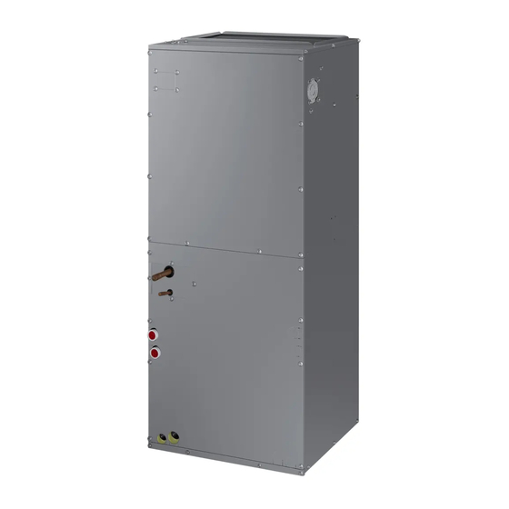
AHU SERIES
INDOOR UNIT
Model :
AC018KNZDCH/AA
AC024KNZDCH/AA
AC030KNZDCH/AA
AC036KNZDCH/AA
AC042KNZDCH/AA
AC048KNZDCH/AA
AC054KNZDCH/AA
CONTENTS
1. Precautions
2. Product Specifications
3. Disassembly and Reassembly
4. Troubleshooting
5. PCB Diagram and Part List
6. Wiring Diagram
7. Reference Sheet
OUTDOOR UNIT
AC018JXADCH/AA
AC024JXADCH/AA
AC030JXADCH/AA
AC036JXADCH/AA
AC042JXADCH/AA
AC048JXADCH/AA
AC054KXADCH/AA
Advertisement
Table of Contents
Troubleshooting

Related Manuals for Samsung AHU Series


Summary of Contents for Samsung AHU Series
- Page 1 All manuals and user guides at all-guides.com SYSTEM AIR CONDITIONER AHU SERIES INDOOR UNIT OUTDOOR UNIT Model : AC018KNZDCH/AA AC018JXADCH/AA AC024KNZDCH/AA AC024JXADCH/AA AC030KNZDCH/AA AC030JXADCH/AA AC036KNZDCH/AA AC036JXADCH/AA AC042KNZDCH/AA AC042JXADCH/AA AC048KNZDCH/AA AC048JXADCH/AA AC054KNZDCH/AA AC054KXADCH/AA AHU SERIES CONTENTS 1. Precautions 2. Product Specifications 3.
-
Page 2: Table Of Contents
5. PCB Diagram and Parts List................5-1 5-1 Indoor Unit ................................5-1-1 MAIN PCB Diagram ..........................5-2 Outdoor Unit ................................. 5-2-1 MAIN PCB ..............................5-2-2 SUB PCB ............................... 5-2-3 MAIN PCB ..............................5-2-4 INVERTER PCB ............................5-2-5 EMI PCB................................ Samsung Electronics... - Page 3 Contents 6. Wiring Diagram ....................6-1 6-1 Indoor Unit ................................6-2 Outdoor Unit ................................. 7. Reference Sheet ....................7-1 7-1 Refrigerating Cycle Diagram .......................... 7-2 Index of Model Name ............................7-2-1 Indoor Unit ..............................7-2-2 Outdoor Unit ............................. Samsung Electronics...
-
Page 4: Precautions
– There is a danger of electric shock. In case the product will not be in use for a long time, the battery of remote control should be kept separately. – Leakage of inside fluid can cause break down of remote control. Samsung Electronics... -
Page 5: Other
- Release the valve caps on High and Low pressure side. - Use L wrench to close the valve on the high pressure side. - Approximately 2 minutes after, close the valve on the low pressure side. - Stop operation of the air conditioner. - Disconnect the pipes. Samsung Electronics... -
Page 6: Product Specifications
It can give the benefit to the installers and aries the reliability of the air conditioner. Long Ambient Operation (In Low Temperature) It can arise the reliability and the capacity of the air conditioner, especially operated in low temperature. Eco-friendly Product (Lead-Free, RoHS, WEEE) Samsung Electronics... -
Page 7: Product Specifications
Extension Length (Elevation) 01E06C-105020- 01E06C-105020-274750- 01E06C-105020- 01E06C-105020-276470- 01E06C-105020- 01E06C-105020- 01E06C-105020- Product Option 27343B-370005 370005 275A64-370005 370005 277D8C-370005 278CA0-370005 27A0B4-370005 Option Code 020000-100000-200000- 020000-100000-200000- 020000-100000-200000- 020000-100000-200000- 020000-100000-200000- 020000-100000-200000- 020000-100000-200000- Installation Option 300000 300000 300000 300000 300000 300000 300000 Samsung Electronics Samsung Electronics... -
Page 8: Specifications Of Optional Items
All manuals and user guides at all-guides.com 2-3 Specifications of optional items 2-3-1 Accessories Item Description Code No. Q’ty Remark Installation manual Essential Offer (Indoor Unit) Card Warranty Cap Drain DB63-10355C Drain Plug DB67-00806A Essential Offer (Outdoor Unit) Rubber Leg DB73-20134A Manual Install DB68-05462A Samsung Electronics... -
Page 9: Disassembly And Reassembly
All manuals and user guides at all-guides.com 3. Disassembly and Reassembly Necessary Tools Item Remarks +SCREW DRIVER Adjustable Wrench (8mm, 10mm, 13mm) M6, M8 Hex Wrench Samsung Electronics... -
Page 10: Indoor Unit
2) Disconnect the Connector Wire that is connected to the indoor unit's PBA 3) Unscrew the 1 fixed screws on middle of the PBA and 4 fixed PBA HOLDER, and disassemble the PBA from the indoor unit. (Use + Screw Driver) Samsung Electronics... - Page 11 2) Loosen 2 of the Left side screw(CCW). 3) Loosen 5 of the front screw(CCW) and detach the 2 Bracket drain and 1 Bracket 4) Pull the Heat Exchanger and Drain. 5) Detach the Drain from indoor Unit. Samsung Electronics...
- Page 12 3) Loosen 5 of the front screw(CCW) and detach the 2 Bracket drain and 1 Bracket Low. 4) Disconnect the Connector Wire that is connected to the Heat Exchanger. 5) Pull the Heat Exchanger and Drain. 6) Detach the Heat Exchanger. Samsung Electronics...
- Page 13 1) Loosen 11 of the front screw(CCW) and detach the Cabinet Front Down. 2) Loosen 6 of the Front screw(CCW) and detach the Bracket. 3) Disconnect the Connector Wire that is connected to the Motor. 5) Pull the A'ssy Fan Blower. Samsung Electronics...
- Page 14 All manuals and user guides at all-guides.com Disassembly and Reassembly Parts Procedure Remark 6) Loosen 4 of the screw and 1 nut on the CASE and Detach the motor and fan. Samsung Electronics...
-
Page 15: Outdoor Unit
1) loosen 1 pcs screw of cover control,and detach it. 2) loosen 5 pcs screws on both right and left cabniet side edges and to detach the cover-top 3) Loosen 7 screwsfixed to disassemble cabi-front , and detach it. Samsung Electronics... - Page 16 All manuals and user guides at all-guides.com Disassembly and Reassembly Parts Procedure Remark common work 4) loosen 7 screws to disassemble the cabi- right ,and detach it. 5) loosen 2 screws to disassemble steel-bar. 6) loosen 3 screws to disassemble cabi-left. Samsung Electronics...
- Page 17 Procedure Remark fan&motor 1) loosen 1 screw as indication and detached the fan. 2) loosen 4 pcs motor screws and disconnect the wire betwwen assy control out and motor. 3) loosen 2 pcs bracket-motor screw and detach it. Samsung Electronics...
- Page 18 Heat exchanger 1) Release the refrigerant at first 2) Looosen fixing screw on both side. 3) disaessembly the pipes in both inlet and outlet with welding torch. 4) detach the heat exchanger. 3-10 Samsung Electronics...
- Page 19 All manuals and user guides at all-guides.com Disassembly and Reassembly Parts Procedure Remark compressor 1) disconnect the compressor lead wire . 2)disassembly the felt comp sound. loosen the 3 bolts at the bottom of Samsung Electronics 3-11...
- Page 20 Cabinet Front RH. (Use +Screw Driver) Cabi Top 1) Unscrew and remove 9 screws on each side of the Cabinet-Top. (Use +Screw Driver) Cabi Install Front 1) Unscrew and remove 1 screw in the Cabinet-Install Front. (Use +Screw Driver) 3-12 Samsung Electronics...
- Page 21 2) Unscrew and remove 4 screws in the Guard Cond. (Use +Screw Driver) Cabi Back RH 1) Pull the sensor from Cabi Back RH. 2) Unscrew and remove 4 screws on each side of the Cabinet Back RH. (Use +Screw Driver) Samsung Electronics 3-13...
- Page 22 Disassembly and Reassembly Parts Procedure Remark Cabi Install Back 1) Unscrew and remove 1 screw in the Cabinet-Install Back. (Use +Screw Driver) Cabi Front LF 1) Unscrew and remove 10 screws in the Cabinet-Front LF. (Use +Screw Driver) 3-14 Samsung Electronics...
- Page 23 All manuals and user guides at all-guides.com Disassembly and Reassembly Parts Procedure Remark 1) Turn 2 mounting nuts as shown in the picture and remove it. (Use Adjustable Wrench) Samsung Electronics 3-15...
- Page 24 1) Separate the Fan Propeller. 2) Unscrew and remove the 8 Motor mounting screws. (Use +Screw Driver) 3) Disconnect the Motor wire From Ass'y Control Out. Bracket Motor 1) Unscrew and remove 2 mounting screws in Bracket Motor. (Use +Screw Driver) 3-16 Samsung Electronics...
- Page 25 All manuals and user guides at all-guides.com Disassembly and Reassembly Parts Procedure Remark Control Out 1) Disconnect 4 Connecters From Ass'y Control Out. 2) Unscrew and remove 1 mounting screw in Control Out. (Use +Screw Driver) 3) Separate Ass'y Control Out. Samsung Electronics 3-17...
- Page 26 Service Valve. (Use +Screw Driver) 4) Separate the pipe from the Entrance/Exit using a welder. When removing the compressor, Heat Exchanger, and Pipe, purge the Coolant inside the Compressor completely and remove the pipe with a welding flame. 3-18 Samsung Electronics...
- Page 27 1) Unscrew and remove 2 mounting screws in Service Valve. (Use +Screw Driver) 2) Separate the pipe from the Entrance/Exit using a welder. Compressor 1) Unscrew and remove 1 mounting nut in Cover Terminal. (Use Adjustable Wrench) 2) Separate the Compressor Felt Sound. Samsung Electronics 3-19...
- Page 28 3) As shown in the picture, unscrew and remove 3 mounting screws from the bottom. (Use Adjustable Wrench) Cond Out 1) Unscrew and remove 3 screws on each side of the Assy Cond Out. (Use +Screw Driver) 2) Separate the Compressor Felt Sound. 3-20 Samsung Electronics...
- Page 29 Cabi Install Front 1) Unscrew and remove 1 screw in the Cabinet-Install Front. (Use +Screw Driver) Guard Cond 1) Pull the sensor from Guard Cond. 2) Unscrew and remove 4 screws in the Guard Cond. (Use +Screw Driver) Samsung Electronics 3-21...
- Page 30 Cabinet-Install Back. (Use +Screw Driver) Cabi Front LF 1) Unscrew and remove 10 screws in the Cabinet-Front LF. (Use +Screw Driver) 1) Turn 2 mounting nuts as shown in the picture and remove it. (Use Adjustable Wrench) 3-22 Samsung Electronics...
- Page 31 1) Unscrew and remove 2 mounting screws in Bracket Motor. (Use +Screw Driver) Control Out 1) Disconnect 4 Connecters From Ass'y Control Out. 2) Unscrew and remove 1 mounting screw in Control Out. (Use +Screw Driver) 3) Separate Ass'y Control Out. Samsung Electronics 3-23...
- Page 32 Compressor completely and remove the pipe with a welding flame. Assy EEV Valve 1) Unscrew and remove 2 mounting screws in Service Valve. (Use +Screw Driver) 2) Separate the pipe from the Entrance/ Exit using a welder. 3-24 Samsung Electronics...
-
Page 33: Troubleshooting
(Communication error for more than 2 minutes) ● : On, ◑ : Flickering, X : OFF ◆ If you turn off the air conditioner when the LED is flickering, the LED is also turned off. Samsung Electronics... -
Page 34: Wired Remocon Error Display
OLP Overheat and Comp. Stop Outdoor unit protection control error [Inverter] IPM over current error Outdoor unit protection control error Compressor V limit error Outdoor unit protection control error DC LINK over/low voltage error Outdoor unit protection control error Samsung Electronics... - Page 35 Communication error between the indoor unit and wired remote controller Wired remote controller error Communication error between the Master and Slave wired remote controllers Wired remote controller error Do not install the electronic heater in the external supply duct connected to the AHU. Samsung Electronics...
-
Page 36: Troubleshooting By Symptoms
8.300 In this case, is the resistance value out of range in the temperature 10.00 table on the right? 12.10 14.70 Indoor temperature sensor 18.00 failure (replace) 22.00 Restart the system after replacing the PCB 28.30 33.90 42.30 Samsung Electronics... -
Page 37: Eva In And Out Sensor (Open/Short)
In this case, is the resistance 8.300 value out of range in the temperature table 10.00 on the right? 12.10 Failure of the indoor heat 14.70 exchanger temperature sensor 18.00 (replace) 22.00 Restart the system after replacing the PCB 28.30 33.90 42.30 Samsung Electronics... -
Page 38: Fan Error
Is the motor connector disconnected from the PCB?(CN301) Connect the connector to PCB and restart the unit Is there foreign substance stuck in the motor fan? Remove the foreign substance and restart the unit Replace the PCB and restart the unit. Samsung Electronics... -
Page 39: Terminal Block's Terminal Fuse(Open)
PCB and terminal block before restart the unit Remove the wire connector from the PCB and measure the resistance between two terminals Is the resistance 0Ω ? Replace the Terminal Block and restart the unit Replace the PCB and restart the unit Samsung Electronics... -
Page 40: Outdoor's Service Valve(Clog)
X (Defrost) X (Timer) (Fan) (Filter) Wire remote controller display E422 Symptom Clogging of outdoor's service valve Valve clog Failure Is the outdoor service valve clogging? Open the outdoor's service valve. Replace the PCB and restart the unit. Samsung Electronics... -
Page 41: Eeprom Error
MAIN PCB? (CN201) Connect the EEPROM PCB to MAIN PCB and restart the unit Connect the EEPROM PCB to MAIN PCB Is the error mode disappear ? Replace the PCB and restart the unit The indoor unit work normaly Samsung Electronics... -
Page 42: Option Error
Wire remote controller display E163 Symptom EEPROM option setting error Option error Failure Input the right option to EEPROM PCB Is the error mode disappear ? Replace the PCB and restart the unit The indoor unit work normaly 4-10 Samsung Electronics... -
Page 43: Setting The Indoor Unit Option Code
You can only check the indoor unit option code in Slave wired remote controller. Setting indoor unit option code is possible when one indoor unit is connected. If more than 2 indoor units are connected, you can only check the Master indoor unit option code. Samsung Electronics 4-11... -
Page 44: Setting An Indoor Unit Address And Installation Option
Press the button anytime during setup to exit without setting. NOTE Address will not be applied if you don't press button. Setting Main/RMC Address of an Indoor unit is available only with a master wired remote controller. 4-12 Samsung Electronics... - Page 45 Use of Heater RESERVED Master / Slave SEG13 SEG14 SEG15 SEG16 SEG17 SEG18 External control External control RESERVED Buzzer RESERVED output SEG19 SEG20 SEG21 SEG22 SEG23 Individual control Heating setting of a remote RESERVED RESERVED compensation controller Samsung Electronics 4-13...
- Page 46 Option code will not be applied if you don't press button. Setting Installation option code is available only with a master wired remote controller. Setting Installation option code is available when there is one on one connection between a wired remote controller and an indoor unit. 4-14 Samsung Electronics...
- Page 47 High speed tap - High speed for High speed for High speed for High speed for "High" speed "High" speed 24 VAC input electric heat electric heat electric heat electric heat Motor control/voltage taps Samsung Electronics 4-15...
- Page 48 All manuals and user guides at all-guides.com Troubleshooting Blower CFM tables AC018KNZDCH/AA,AC024KNZDCH/AA,AC030KNZDCH/AA,AC036KNZDCH/AA, AC042KNZDCH/AA,AC048KNZDCH/AA,AC054KNZDCH/AA AC018KNZDCH/AA HP : 1/3 Default motor taps: High / Mid /Low = 4/3/2 Motor TapP (inwg) CFMM otor Tap P(inwg)C 44444444 4 = Default Settin g Q (CFM) 4-16 Samsung Electronics...
- Page 49 All manuals and user guides at all-guides.com Troubleshooting AC024KNZDCH/AA HP : 1/3 Default motor taps: High / Mid /Low = 4/2/1 Motor TapP (inwg) CFMM otor Tap P(inwg)C = Default Settin g 2503 4505 6507 Samsung Electronics 4-17...
- Page 50 1160 1126 0.25 0.25 1109 1092 1055 1019 1314 1282 0.25 0.25 1266 1251 1217 1183 1149 1113 1076 1039 1000 1060 = Default Settin g 1025 0.25 1009 4005 6007 8009 1000 1100 1200 1300 1400 4-18 Samsung Electronics...
- Page 51 1160 1126 0.25 0.25 1109 1092 1055 1019 1314 1282 0.25 0.25 1266 1251 1217 1183 1149 1113 1076 1039 1000 1060 = Default Settin g 1025 0.25 1009 4005 6007 8009 1000 1100 1200 1300 1400 Samsung Electronics 4-19...
- Page 52 1005 1137 1315 1101 1282 0.25 1083 0.25 1266 1064 1251 1025 1217 1184 1149 1113 1076 1039 1000 1180 = Default Settin g 1147 0.25 1128 1110 1074 1035 6007 8009 1000 1100 1200 1300 1400 4-20 Samsung Electronics...
- Page 53 1280 1224 1158 1078 1379 1739 1293 1705 1210 1670 1130 1633 1045 1597 1559 1522 1485 1446 1406 1475 = Default Settin g 1410 1348 1282 1216 1148 1076 1003 3005 7009 1100 1300 1500 1700 Samsung Electronics 4-21...
- Page 54 1940 1407 1923 1325 1887 1240 1847 1159 1807 1077 1762 1714 1664 1608 1642 = Default Settin g 1587 0.25 1557 1528 1472 1412 1355 1294 1233 1172 1109 3005 7009 1100 1300 1500 1700 1900 4-22 Samsung Electronics...
-
Page 55: Items To Be Checked First
The compressor operates in a reverse cycle to remove Indoor fan and outdoor fan stop operation intermittently exterior ice in a HEAT mode, and indoor fan and outdoor in a HEAT mode. fan do not operate intermittently for within 20% of the total heater operation Samsung Electronics 4-23... -
Page 56: Pcb Diagram And Parts List
All manuals and user guides at all-guides.com 5. PCB Diagram and Part List 5-1 Indoor Unit 5-1-1 MAIN PCB Diagram - AC018KNZDCH, AC024KNZDCH, AC030KNZDCH, AC036KNZDCH, AC042KNZDCH, AC048KNZDCH, AC054KNZDCH Samsung Electronics... - Page 57 CN302 – COMM CN311 – 2 WIRE COMM SUB #1 : F1 ‒ I NDOOR/OUTDOOR COMM #1 : 12V #2 : F2 ‒ I NDOOR/OUTDOOR #2 : COM2̲PCTRL̲MICOM COMM #3 : COM2̲VCHECK̲A #3 : V1 ‒ 12V #4 : COM2̲VCHECK̲B #4 : V2 ‒ SGND #5 : COM2̲MICOM̲AD #5 : F3 ‒ W IRED CONTROLLER #6 : VCC ON/OFF CTRL COMM #7 : COM2̲ENABLE #6 : F4 ‒ W IRED CONTROLLER #8 : COM2̲C COMM #9 : COM2̲D #10 : COM2̲TX #11 : COM2̲RX #12 : SGND Samsung Electronics...
-
Page 58: Outdoor Unit
All manuals and user guides at all-guides.com 5-2 Outdoor Unit 5-2-1 Main PCB AC018JXADCH 11 12 Samsung Electronics... - Page 59 CN201 : Downloader #1~#5 : EEV SIGNAL #1 : COM1(F1) #1~#2 : OUTDOOR THERMISTOR #1~#10 : Download #6 : DC12V #2 : COM2(F2) #3~#4 : DISCHARGE THERMISTOR #5~#6 : COND THERMISTOR ⑨ ⑩ ⑪ ⑫ CN901 : BLDC MOTOR CN551: Downloader CN451 : COMP POWER CN051 : Reactor #1: DV310V #1~#10 : Download #1 : COMP U-Phase #1~#2 : Reactor #3: GND #2 : COMP V-Phase #4: DC15V #3 : COMP W-Phase #5: FAN̲PWM #6: FAN̲Feedback Samsung Electronics...
-
Page 60: Sub Pcb
All manuals and user guides at all-guides.com PCB Diagram and Part List 5-2-2 SUB PCB AC018JXADCH ① ② CN12 : DC12V CN951 : SIGNAL TO MAIN PCB #1 : DC12V #1~#28 : SIGNAL TO MAIN PCB #2 : GND Samsung Electronics... -
Page 61: Main Pcb
LOW PRESSURE S/W B04B-XARK-1 BLU 3711-001038 CN305 COMM INV SMW250-06 WHT 3711-000939 CN801 ERROR/COMP CHECK SMW250-04 RED 3711-000176 CN12 DC12V YW396-02V BLU 3711-000997 CN803 EEV1 SMW250-05 BLU 3711-001036 CN802 EEV4 SMW250-06 BLU 3711-001084 CN403 OUT TEMP/COND/DISQ/OLP SMW250-08 WHT Samsung Electronics... -
Page 62: Inverter Pcb
Reactor-A1/B1 Reactor-A2/B2 CN50(2PIN/RED)-Communication CN22-Downloader #Reactor-A2 : WHT #Reactor-A2 : BLK #1 : RXD, #2 : TXD #1 : RXD̲ATARO, #2 : TXD̲ATARO #Reactor-B2 : WHT #Reactor-B2 : BLK #3 : GND, #4 : DC 5V #3, #8 : N.C, #4~#7 : DATA signal #5 : DC 12V, #6 : INV. SMPS signal #9 : GND, #10 : DC 5V ⑤ ⑥ ⑦ ⑧ CN21-DAC/ENCODER CN91-FAN2 CN90-FAN1 CN71-COMP. For S/W engineer debugging #1 : DC 360V #1 : DC 360V #1 : COMP. U-phase(RED) #2 : N.C #2 : N.C #2 : COMP. V-phase(BLU) #3 : GND #3 : GND #3 : COMP. U-phase(YEL) #4 : DC 15V #4 : DC 15V #5 : FAN RPM #5 : FAN RPM #6 : FAN RPM feedback #6 : FAN RPM feedback Samsung Electronics... - Page 63 #3 : GND #4 : DV15V #3 : GND #4 : DV15V #2 : Compressor V-phase(BLU) #2 :N-Phase/SKY #5 : FAN RPM #6 : FAN RPM #5 : FAN RPM #6 : FAN RPM #3 : Compressor W-phase(YEL) Feedback Feedback Samsung Electronics...
-
Page 64: Emi Pcb
All manuals and user guides at all-guides.com PCB Diagram and Part List 5-2-5 EMI PCB AC024JXADCH, AC030JXADCH, AC036JXADCH, AC042JXADCH, AC048JXADCH, AC054KXADCH ① ② ③ L1-AC POWER L phase N1-AC POWER N phase CN01-AC POWER L1 : BRN N1 : SKY-BLU #1-#3 : AC 220~240V Samsung Electronics... -
Page 65: Wiring Diagram
All manuals and user guides at all-guides.com 6. Wiring Diagram 6-1 Indoor Unit - AC018KNZDCH / AC024KNZDCH / AC030KNZDCH / AC036KNZDCH / AC042KNZDCH / AC048KNZDCH / AC054KNZDCH This Document can not be used without Samsung’s authorization. Samsung Electronics... -
Page 66: Outdoor Unit
All manuals and user guides at all-guides.com 6-2 Outdoor Unit - AC018JXADCH This Document can not be used without Samsung’s authorization. Samsung Electronics... - Page 67 All manuals and user guides at all-guides.com - AC024JXADCH, AC030JXADCH, AC036JXADCH, AC042JXADCH, AC048JXADCH This Document can not be used without Samsung’s authorization. Samsung Electronics...
- Page 68 All manuals and user guides at all-guides.com - AC054KXADCH This Document can not be used without Samsung’s authorization. Samsung Electronics...
-
Page 69: Reference Sheet
You can open the valve by turning the need valve counterclockwise using hex wrench, and it is used for vacuum, gas purging, coolant injection, coolant purging, and indoor-outdoor unit connection. ACCUMULATOR Accumulator prevents the flow of liquid-state coolant into the compressor. (Liquid-state coolant flowing into the compres- sor will overload the compressor.) Samsung Electronics... -
Page 70: Index Of Model Name
DELUXE <- Basic Cooling only STANDARD R134A Heat Pump FLAGSHIP + TROPICAL PREMIUM + TROPICAL DELUXE + TROPICA <- Basic Model STANDARD + TROPICAL ※ "/" can be removed from the buyer card if there are not enough digits. Samsung Electronics... -
Page 71: Outdoor Unit
PREMIUM + TROPICAL HEAT PUMP DELUXE + TROPICA <- Basic Model Cooling only STANDARD + TROPICAL R134A Heat Pump ★ ※ MCD: Dummy mock-up model ※ “/” can be removed from the buyer card if there are not enough digits. Samsung Electronics... - Page 72 China china.samsungportal.com © Samsung Electronics Co., Ltd. March. 2016. This Service Manual is a property of Samsung Electronics Co., Ltd. Printed in Korea. Any unauthorized use of Manual can be punished under applicable International and/or domestic law. Code No. AC-00154E_1...
Need help?
Do you have a question about the AHU Series and is the answer not in the manual?
Questions and answers