
Related Manuals for Samsung AC024KN4DCH


Summary of Contents for Samsung AC024KN4DCH
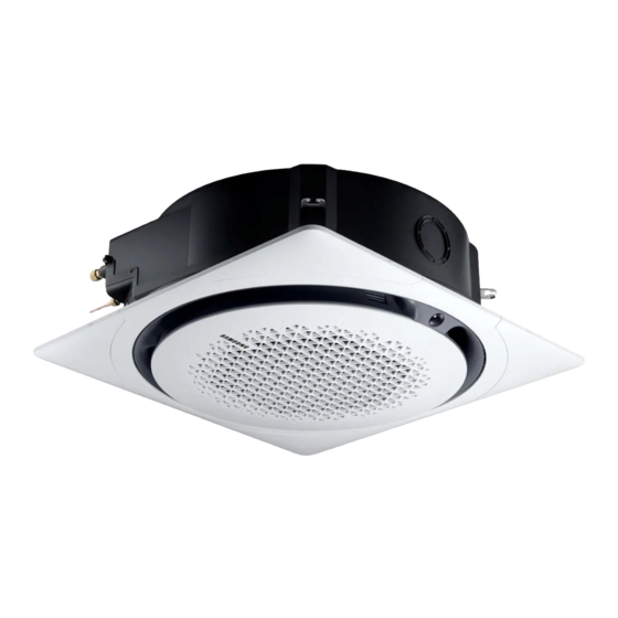
- Page 1 Air conditioner Installation manual AC✴✴✴KN4DCH • Thank you for purchasing this Samsung air conditioner. • Before operating this unit, please read this manual carefully and retain it for future reference.
-
Page 2: Table Of Contents
Contents Safety Information Installation Procedure Step 1 Checking and preparing accessories Step 2 Choosing the installation location Step 3 Optional: Insulating the body of the indoor unit Step 4 Installing the indoor unit Step 5 Purging inert gas from the indoor unit Step 6 Cutting and flaring the pipes Step 7 Connecting the assembly pipes to the refrigerant pipes Step 8 Performing the gas leak test... -
Page 3: Safety Information
• This manual explains how to install an indoor unit with a split system with two SAMSUNG units. The use of other types of units with different control systems may damage the units and invalidate the warranty. - Page 4 Safety Information Installing the unit • Always verify that a suitable grounding connection is available. • Verify that the voltage and frequency of the power WARNING supply comply with the specifications and that the installed power is sufficient to ensure the operation IMPORTANT: When installing the unit, always remember of any other domestic appliance connected to the to connect first the refrigerant tubes, then the electrical...
-
Page 5: Installation Procedure
Installation Procedure Do not install the air conditioner in following places. Installation template (1 ea) Bushing bracket (1 ea) • Place where there is mineral oil or arsenic acid. Resin parts flame and the accessories may drop or water may leak. The capacity of the heat exchanger may reduce or the air conditioner may be out of order. - Page 6 Installation Procedure Indoor unit dimensions Unit: mm (inch) Category Square panel Circular panel 1050 (41.37) 1000 (39.40) 358 (14.11) 883 (34.79) Front Ceiling opening dimension (4.57) 960 (37.80) [950 (37.40) - 960 (37.80)] (15.17) (15.92) (14.07) Large (15.17) (15.92) (14.07) Small →...
- Page 7 Model AC018KN4DCH AC024KN4DCH AC030KN4DCH AC036KN4DCH AC042KN4DCH AC048KN4DCH Chassis Small Large 947 x 947 x 281 947 x 947 x 281 947 x 947 x 365 947 x 947 x 365 947 x 947 x 365 947 x 947 x 365 Net dimension (37.28 x 37.28 x...
-
Page 8: Step 3 Optional: Insulating The Body Of The Indoor Unit
• Do not hold the discharge while carrying the indoor (102.76 x 5.12 in.) (37.28 x 37.28 x unit to avoid the possibility of breakage. AC024KN4DCH 11.06 in.) • You must hold the hanger plate on the corner and AC030KN4DCH carry the indoor unit. - Page 9 2 Perform the following steps to install inspection holes in accordance with the panel type. Ceiling support a For the recessed installation of the square panel. • Install an inspection hole to the direction of connection parts of the refrigerant pipe and the drain hose.
-
Page 10: Step 5 Purging Inert Gas From The Indoor Unit
Installation Procedure 7 Adjust the unit to the appropriate position, taking into Step 6 Cutting and flaring the pipes account the installation area for the front panel. 1 Make sure that you have the required tools available: • Place the pattern sheet on the indoor unit. pipe cutter, reamer, flaring tool, and pipe holder. -
Page 11: Step 7 Connecting The Assembly Pipes To The Refrigerant Pipes
5 Check that the flaring is correct, referring to the Outer Diameter (D) Torque illustrations below for examples of incorrect flaring. N·m lbf·ft 6.35 14 to 18 10.3 to 13.3 9.52 34 to 42 25.1 to 31.0 12.7 49 to 61 36.1 to 45.0 15.88 68 to 82... -
Page 12: Step 8 Performing The Gas Leak Test
Installation Procedure Step 9 Insulating the refrigerant CAUTION pipes • Connect the indoor and outdoor units using pipes with flared connections (not supplied). For the lines, Once you have checked that there are no leaks in the use insulated, unwelded, degreased and deoxidized system, you can insulate the piping and hose. - Page 13 CAUTION CAUTION • Install the insulation not to get wider and use the • Must fit tightly against body without any gap. adhesives on the connection part of it to prevent • All refrigerant connection must be accessible, in order moisture from entering.
-
Page 14: Step 10 Installing The Drain Hose And Drain Pipe
Installation Procedure • When installing insulation in the places and 5 Push the drain hose up to insulation when connecting conditions below, use the same insulation that is the drain hose to drain socket. used for high humidity conditions. Drain socket Metal clamp <Geological condition>... -
Page 15: Step 11 Performing The Drainage Test
• Do not give the hose an upward gradient beyond • Max. allowable bending angle. the connection port. This will cause water to flow backwards when the unit is stopped, resulting in water leaks. Under gradient Indoor unit Max. 30˚ Ceiling NOTE • Do not apply force to the piping on the unit side... - Page 16 Installation Procedure CAUTION CAUTION • The leak test must be performed for at least 24 hours. • When the float switch is not detected due to insufficient water on the drain pan, the drain 2 Check the condensed water drainage: pump will not work.
- Page 17 Bushing bracket installation IF the condult tube is used, bracket must be installed as shown in the picture to fix the conduit tube. Indoor unit Push < 1 conduit tube > < 2 conduit tube > NOTE • Please follow national and local electrical codes. Additional electrical connection components may be required. English...
- Page 18 Installation Procedure Wiring work Selecting compressed ring termial Silver solder Norminal dimensions for cable [mm (Inch 1.5(0.002) 2.5(0.003) 4(0.006) Norminal dimensions for screw [mm (Inch)] 4(0.15) 4(0.15) 4(0.15) 4(0.15) 4(0.15) Standard dimension [mm (Inch)] 9.5(0.37) (0.25) (0.31) (0.25) (0.33) Allowance [mm (Inch)] ±0.2(±0.007) ±0.2(±0.007) ±0.2(±0.007)
-
Page 19: Step 12 Connecting The Power And Communication Cables
Step 12 Connecting the power and 1 phase communication cables CAUTION For connecting the power and • Always remember to connect the refrigerant pipes communication cables before performing the electric connections. When disconnecting the system, always disconnect the electric cables before disconnecting the refrigerant pipes. -
Page 20: Step 13 Optional: Extending The Power Cable
Installation Procedure CAUTION Tightening torque (lbf.ft) • After peeling off the tube wire, you must insert a M3.5 0.59 to 0.89 contraction tube. 0.89 to 1.1 Power cable (provided by us) • Screws on terminal block must not be unscrewed with the torque less than 0.89 lbf.ft. - Page 21 • After compressing it, pull both sides of the wire to WARNING make sure it is firmly pressed. • In case of extending the electric wire, please DO NOT use a round-shaped Pressing socket. Method 1 Method 2 – Incomplete wire connections can cause electric Compress it 4 times.
- Page 22 Installation Procedure 1 Enter the mode for setting the options: SEG1 SEG2 SEG3 SEG4 SEG5 SEG6 a Remove the batteries from the remote control. b While holding down the (Temp) and SEG7 SEG8 SEG9 SEG10 SEG11 SEG12 (Timer) buttons simultaneously, insert the batteries into the remote control.
- Page 23 Take the steps presented in the following table: Steps Remote control display 1 Set the SEG2 and SEG3 values: a Set the SEG2 value by rotating the Wheel counterclockwise until the value you want to set appears on the remote control display. SEG2 b Set the SEG3 value by rotating the Wheel clockwise until the value you want to set appears on the remote...
- Page 24 Installation Procedure Steps Remote control display b Set the SEG8 value by rotating the Wheel clockwise until the value you want to set appears on the remote control display. SEG8 When you rotate the Wheel, values appear in the following order: 6 Press the (Mode) button.
- Page 25 Steps Remote control display 11 Set the SEG14 and SEG15 values: a Set the SEG14 value by rotating the Wheel counterclockwise until the value you want to set appears on the remote control display. SEG14 b Set the SEG15 value by rotating the Wheel clockwise until the value you want to set appears on the remote control display.
- Page 26 Installation Procedure Steps Remote control display When you rotate the Wheel, values appear in the following order: 16 Press the (Mode) button. Fan and Off appear on the remote control display. 17 Set the SEG21 and SEG22 values: a Set the SEG21 value by rotating the Wheel counterclockwise until the value you want to set appears on the remote control display.
- Page 27 3 Check whether the option values that you have set are NOTE correct by pressing the (Mode) button repeatedly • The remote control display and buttons may vary depending on the model. [SEG2, SEG3] [SEG4, SEG5] [SEG6, SEG8] [SEG9, SEG10] 1 Enter the mode for setting the options: a Remove the batteries from the remote control, [SEG11, SEG12]...
- Page 28 Installation Procedure On (SEG1 to SEG12) Off (SEG13 to SEG24) Take the steps presented in the following table: Steps Remote control display 1 Set the SEG2 and SEG3 values: a Set the SEG2 value by pressing the (Low Fan) button repeatedly until the value you want to set appears on the remote control display.
- Page 29 Steps Remote control display 5 Set the SEG6 and SEG8 values: a Set the SEG6 value by pressing the (Low Fan) button repeatedly until the value you want to set appears on the remote control display. SEG6 b Set the SEG8 value by pressing the (High Fan) button repeatedly until the value you want to set appears on the remote control display.
- Page 30 Installation Procedure Steps Remote control display b Set the SEG12 value by pressing the (High Fan) button repeatedly until the value you want to set appears on the remote control display. SEG12 When you press the (Low Fan) or (High Fan) button, values appear in the following order: 10 Press the (Mode) button.
- Page 31 Steps Remote control display 15 Set the SEG18 and SEG20 values: a Set the SEG18 value by pressing the (Low Fan) button repeatedly until the value you want to set appears on the remote control display. SEG18 b Set the SEG20 value by pressing the (High Fan) button repeatedly until the value you want to set appears on the remote control display.
- Page 32 Installation Procedure Steps Remote control display b Set the SEG24 value by pressing the (High Fan) button repeatedly until the value you want to set appears on the remote control display. SEG24 When you press the (Low Fan) or (High Fan) button, values appear in the following order: 3 Check whether the option values that you have set are Setting the indoor unit addresses...
- Page 33 Option SEG1 SEG2 SEG3 SEG4 SEG5 SEG6 Setting main Indoor unit Indoor unit Function Page Mode address number number Indication Details Indication Details Indication Details Indication Details Indication Details No main Reserved Indication address Tens Units Main 0 to 1 0 to 9 details digit...
- Page 34 Installation Procedure Option SEG1 SEG2 SEG3 SEG4 SEG5 SEG6 Use of external Use of central Compensation of Function Page Mode temperature control the fan RPM sensor Indication Details Indication Details Indication Details Indication Details Indication Details Disuse (recessed installation) Disuse Disuse High-ceiling Reserved...
- Page 35 Option SEG19 SEG20 SEG21 SEG22 SEG23 SEG24 Individual Heating setting Cycle time of Function Page control with compensation Swing remote control Indication Details Indication Details Indication Details Indication Details No function No function 0 or 1 Indoor 1 Disuse seconds assigned assigned (default)
- Page 36 Installation Procedure For the installation of the circular 4 Rotate the paper compass diametrically to draw a circle on the ceiling. panel Making a circular opening on the ceiling Use a paper compass printed on the indoor unit package. (attached inside to the upper part) 1 Use a bolt or a pin to fix pivot point of the paper compass on center of the ceiling.
-
Page 37: Troubleshooting
Troubleshooting Indoor unit display indications Condition Ice blue Yellow green Blue Power reset (blinking once every 2 seconds) In the defrost operation (blinking once every 10 seconds) Open or short circuit error of the indoor-temperature sensor Error of the outdoor unit Communication error between the indoor and outdoor units Open or short circuit error of a sensor (evaporator-in, evaporator-out, or discharge sensor) in the indoor unit...
Need help?
Do you have a question about the AC024KN4DCH and is the answer not in the manual?
Questions and answers