Advertisement
Quick Links
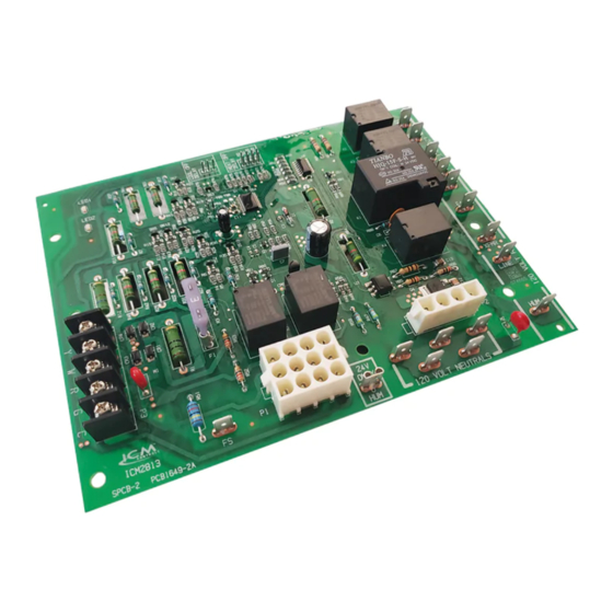
ICM2813
Integrated Furnace Control Board
Installation, Operation & Application Guide
For more information on our complete range of
American-made products – plus wiring diagrams,
troubleshooting tips and more,
visit us at www.icmcontrols.com
The ICM2813 is a form, fit, and functional replacement for the Lennox and White Rodgers boards shown in the cross reference
section of this guide. The ICM2813 automated gas ignition control board monitors the ignition sequence including the inducer,
pressure switch, hot surface igniter, gas valve, flame sense, and circulating blower while maintaining full safety circuit monitoring
including the high limit switch, roll out switch and auxiliary limit switch circuits. Onboard diagnostics will indicate when a fault
condition exists.
Upon a call for heat, the thermostat will energize the W terminal with 24 VAC. With the heat call in place, the inducer fan and
humidifier (optional) will be energized thus closing a pressure safety switch. The control will enter a 15 second inducer pre purge
cycle. Upon verification of the pressure switch closure and completion of the 15 second inducer pre-purge, the hot surface igniter
is energized. There is a 20 second igniter warm up period before energizing the gas valve. Once the gas valve is energized,
gas flows into the burners where it is ignited by the hot surface igniter. Once the burners are on, the flame is sensed by a flame
rectification circuit and flame sensor. There is a 4 second trial for ignition period where the control checks the flame signal and
proves the flame. Once flame is established, there will be a 45 second heat ON delay before energizing the main blower. When
the call for heat ends, the gas valve is de-energized, burners go off, flame is proven lost and there is a fixed 5 second inducer
post purge to purge any residual exhaust gases from the system. Following the inducer post purge, the inducer and humidifier are
turned off and subsequently the heat blower is turned off after the user selected off delay time expires. Upon a call for cooling, the
Y terminal is energized with 24 VAC and a 2 second cool blower ON delay begins. After the ON delay expires, the EAC and cool
blower outputs are energized. Once the call for cooling ends, there is a user selectable 2 second or 45 second cooling blower
OFF delay to purge the residual cool air from the duct work. At the end of the OFF delay, the cool blower and EAC are turned off.
There is a 5 minute self healing recovery which occurs if the pressure switch is stuck open. The inducer will run for 150 seconds
then enter a 5 minute self healing recovery. This cycle will repeat until the pressure switch closes.
There will be a 1 hour lock out if the flame is not established and proved within 5 successive attempts. After one hour in lockout,
the control will reset automatically.
• Controls the gas valve, inducer draft motor, circulating
blower and hot surface ignitor
• Monitors system pressure and limit switches
• Microprocessor based precision
• Diagnostic LEDs aid in testing and troubleshooting
Lennox: 10M9301, 12L6901, 32M8801, 56L8401, 24L8501,
White-Rodgers: 50A65-120, 50A65-121, 50A62-120,
• Electrical Rating @ 77°F (25°C)
• Input Voltage: 18-30 VAC, 60 Hz
• Ignitor Current: 2.0 amp @ 80 VAC, 60 Hz (resistive)
• Inducer Relay: 2.2 FLA–3.5 LRA @ 120 VAC
• Blower Relay: 14.5 FLA–25.0 LRA @ 120 VAC
• Gas Valve Relay: 1.5 amp @ 25 VAC, 60 Hz 0.6 pf
Environmental
• Operating Temp Range: -40° to 176°F (-40° to 80°C)
• Humidity Range: 5 to 95% relative humidity
Introduction
Mode of Operation
Lockout Features
Features
Replaces
63K8901, 97L4801, 100925-01, 100925-03,
17W9201, 23W5101, 30W2501, 69M0801,
69M1501, 83M00
50A62-121, 50A62-820, 21D83M-843,
50A66-122, 50A66-123
Specifications
(Heat / Cool / Fan)
(non-condensing)
Advertisement

Related Manuals for ICM Controls ICM2813


Summary of Contents for ICM Controls ICM2813
- Page 1 Introduction The ICM2813 is a form, fit, and functional replacement for the Lennox and White Rodgers boards shown in the cross reference section of this guide. The ICM2813 automated gas ignition control board monitors the ignition sequence including the inducer, pressure switch, hot surface igniter, gas valve, flame sense, and circulating blower while maintaining full safety circuit monitoring including the high limit switch, roll out switch and auxiliary limit switch circuits.
- Page 2 8. Remove wiring harness from circuit board. 9. Remove screws or any other fasteners and old circuit board. Install New Control 1. Ground yourself properly before installing the new ICM2813 control board. 3. Connect all line/low voltage, accessory, thermostat and ground wires.
- Page 3 LED Fault Codes Status Description Trouble Shooting Tips Normal operation Control board failure Check for proper input voltage and check the fuse; if not resolved replace control. Ignition failure (soft Clean or replace the flame sensor, check the igniter for proper operation & input voltage, check lockout) the transformer’s common is grounded to earth ground.
- Page 4 Wiring Diagram GRN/YEL BLOWER CAP-1 MOTOR COOL LED1 HEAT PARK PARK XFRM LINE ONLY ICM2813 120 VOLT NEUTRALS Flame Sensor INDUCED NEUTRAL DRAFT LINE MOTOR P1 Plug Pin Out Legend 1 = High limit output = Electronic air 2 = N/A...
Need help?
Do you have a question about the ICM2813 and is the answer not in the manual?
Questions and answers