Table of Contents
Advertisement
Advertisement
Table of Contents

Subscribe to Our Youtube Channel
Related Manuals for ICM Controls ICM326H


Summary of Contents for ICM Controls ICM326H
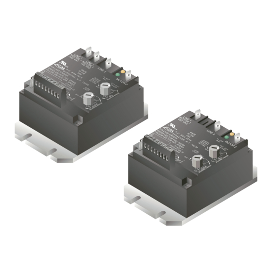
- Page 1 ICM326H/ICM327H Line Voltage Head Pressure Control With built-in transformer Optional heat pump override Application Guide For information on our complete range of American-made products — plus wiring diagrams, troubleshooting tips and more, visit us at www.icmcontrols.com...
-
Page 2: Table Of Contents
Table of Contents Specifications ................... Connections for ICM326H at 120 VAC ............. Connections for ICM326H at 208/240 VAC ..........Connections for ICM327H at 480 VAC ............. Connecting the Probe ................Connections for Heat Pump Systems ............Mode of Operation ................... -
Page 3: Specifications
• Mounting: – Surface mount using (4) #8 screws (4.5”L X 3”W X 2”H) – The ICM326H and 327H should be surface mounted to a clean metal, or other thermally-conductive surface for maximum heat dissipation – It is recommended that the ICM326H and 327H be mounted away from the condenser exhaust air to maintain lower operating temperatures ELECTRICAL SHOCK HAZARD –... -
Page 4: Connections For Icm326H At 120 Vac
Connections for ICM326H at 120 VAC 1. Remove power from system. 2. Add wire from Line 1 wire to Line 1 terminal. 3. Cut Line 2 wire; affix motor side to Motor 2 terminal, and line side to Line 2 terminal. -
Page 5: Connections For Icm326H At 208/240 Vac
Connections for ICM326H at 208/240 VAC 1. Remove power from system. 2. Add wire from Line 1 wire to Line 1 terminal. 3. Cut Line 2 wire; affix motor side to Motor 2 terminal, and line side to Line 2 terminal. -
Page 6: Connections For Icm327H At 480 Vac
Connections for ICM327H at 480 VAC 1. Remove power from system. 2. Add wire from Line 1 wire to Line 1 terminal. 3. Cut Line 2 wire; affix motor side to Motor 2 terminal, and line side to Line 2 terminal. -
Page 7: Connecting The Probe
Connecting the Probe 1. Install the temperature probe several bends into the condenser. It can be attached to the U-bend or placed between the fins in the upper 1/3 of the condenser (see Pages 10-12 for more information). Note: The response of the system can be fine tuned by repositioning the probe. -
Page 8: Connections For Heat Pump Systems
Connections for Heat Pump Systems 1. The heat pump terminals accept the line voltage signal from the reversing valve holding coil. Make a parallel connection from the reversing valve to HP terminals. 2. If the heat pump is in the Heating mode and the reversing valve is N.O. -
Page 9: Setting The Cutout Speed
As the temperature being sensed decreases, the output voltage decreases. The output voltage may decrease to the determined cutout speed. Upon reaching the Cutout Speed knob setting, the output voltage will go to zero volts. System restart occurs when the temperature exceeds 70°F. With probe temperatures below 70°F, the motor remains off. -
Page 10: Setting The Hard Start Time
Setting the Hard Start Time During the Hard Start mode, full voltage is applied to the motor during startup to overcome windmilling and to lubricate the bearings. The position of the Hard Start knob determines the time period of the Hard Start mode. -
Page 11: Troubleshooting
Troubleshooting SYMPTOM REMEDY Unit fails to The sensor may not be connected or it is defective. start With the probe disconnected, use an ohmmeter to measure the resistance between the probe wires. It should match the chart in Appendix B. If you read an OPEN or SHORT, replace the sensor. -
Page 12: Appendix A
Appendix A Mounting a sensor into the condenser versus mounting it on the liquid line When a sensor is mounted into the condenser, the control responds more rapidly to changes in head pressure than when it is mounted on the liquid line. This is especially true for high efficiency condensers. -
Page 13: Icm326H Typical Installation
ICM326H Typical Installation... -
Page 14: Icm327H Typical Installation
ICM327H Typical Installation... - Page 15 6333 Daedalus Drive, Cicero, NY 13039 (Phone) 315-233-5266 (Toll Free) 800-365-5525 (Fax) 315-233-5276 www.icmcontrols.com LIA148-1...
Need help?
Do you have a question about the ICM326H and is the answer not in the manual?
Questions and answers