Table of Contents
Advertisement
Quick Links
Replacement Description
The ICM275 Gas Furnace Control Center is a new generation control for the
replacement market.
The ICM275 Gas Furnace Control Center is designed to function similarly to previous
control center designs, while incorporating some of the latest features in furnace
control center technology.
It is a form, fit and functional replacement of the OEM control for the following Carrier
control center part numbers: HH84AA021, HH84AA001, HH84AA003, HH84AA005,
HH84AA009, HH84AA014, HH84AA015, or CESO110019.
Specifications
• Input Voltage
- Terminals: PR-1, PR-2, L1, L2 and COM ..................................................... 120 VAC
- Terminals: SEC-1 and SEC-2 ................................................................... 18-30 VAC
• Line Frequency .................................................................................................. 60 Hz
• Operating Temperature ..................................................................... -40ºF to +176ºF
• Maximum Operating Humidity .................................................................... 95% R.H.
• Time Delays
- Heat ON .................................................................................................. 60 Seconds
- Heat OFF ......................................................................................... 60-240 Seconds
- Cool OFF (R18 Cut) ................................................................................ 90 Seconds
Introduction
This application guide covers the installation of the Gas Furnace Control Center, Part
No. ICM275, in an intermittent ignition, induced draft, or condensing gas furnace.
Safety Considerations
Installing and servicing heating equipment can be hazardous due to gas and electrical
components. Only trained personnel should install or service heating equipment.
Untrained personnel can perform basic maintenance functions such as cleaning coils,
or cleaning and replacing filters. All other operations should be performed by trained
personnel only. When working on heating equipment, observe precautions in the
literature, on tags, and on labels attached to the unit.
Follow all safety codes. Wear safety glasses and work gloves. Have a fire extinguisher
available.
CAUTION!: Before beginning the installation or modification, be sure the main
electrical disconnect switch is in the OFF position.
CAUTION!: Failure to carefully read and follow these instructions before servicing
or operating this control, could result in personal injury, death and/or
property damage.
Operational Differences and Added Features
The following is a description of the slight operational differences and added
features. Refer to ICM275 Component Layout (Page 3) for location of control center
components.
Fan Control
Center
Non-condensing @ 50ºC
Operation with new blower and humidifier relays:
The previous design control centers used a SPST-NC or DPST-NC heating fan relay
(HFR of E2) and a DPDT cooling fan relay (CFR or 2F) for blower and humidifier
terminal operation. This new control center uses a SPST-NO blower relay (BLWR)
and a SPDT blower speed change relay (hi/lo) for blower operation, and a SPST-NO
humidifier relay.
1. The low-speed blower will not operate on a transformer failure as on previous
designs.
2. If JW1 jumper is cut between R and GH terminals, a constant low-speed blower
will occur without any thermostat inputs to the control center. A GC or Y signal to
the control center will not bring on the hi-speed blower for cooling operation. JW1
jumper must not be cut on cooling applications.
3. The humidifier H terminal is energized with low-speed blower operation. In cooling
operation, the humidistat and humidifier water supply should be turned off to ensure
the humidifier does not operate.
24 volt circuit protection:
An automotive type, 3 amp fuse is provided to protect the transformer and thermostat
from shorts in the low-voltage circuitry. An open fuse will initiate a constant low-speed
blower. Refer to the ICM275 Component Layout (Page 3) for location on control center.
Low-speed continuous "G" blower and 90-second hi-speed blower OFF delay
option:
Resistor (R18) on the control center can be cut to achieve heating speed continuous
blower with a thermostat (R-G) call and a hi-speed blower with a 90 second OFF delay
with a thermostat (R-Y) call.
CAUTION!: Do not cut R18 on twinned furnace applications.
Installation Instructions
CAUTION!: Verify power is removed from the control by removing fuse or turning
off circuit breaker.
1. Disconnect wiring from blower control center. Tag each wire as it is disconnected
from the old furnace control center. Disconnect all wiring hookups.
2. Remove existing blower control center.
3. Install the ICM275 fan control center into the control center box. Be sure that the top
edge of the ICM275 is in the mounting slot, just like the original board.
CAUTION!: If the ICM275 is not installed correctly (i.e.: behind the slot), an
electrical short could occur.
4. Reconnect all of the wire(s) that were removed in Step 1 above, to the proper
terminals.
5. Turn power to ON position and check unit sequence of operation per unit installation
instructions.
6. These instructions must be placed with the original unit instruction packet, or with
the unit for future reference.
Blower Operating Modes
Input From
Resistor (R18) Uncut
Thermostat
W
Lo-speed heating blower*
G
Hi-speed cooling blower
Y
No blower
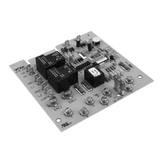
Component Layout
SPCB-1
LO
PCB503-1
HI
PR1
L1
PR2
L2
COM
EAC-2
EAC-2
EAC-1
EAC-1
Y
H
W
JW1
* 60-second ON delay
Resistor (R18) Cut
and 60-240 second
adjustable OFF delay
Lo-speed heating blower*
** 90-second OFF delay
Lo-speed heating blower
Hi-speed cooling blower**
SEC-1
SEC-2
INC
240
ATO
3-amp
Fuse
GH
G
F1
3A ATO
R
C
ATO 3-amp Fuse
Advertisement
Table of Contents

Related Manuals for ICM Controls ICM275


Summary of Contents for ICM Controls ICM275
-
Page 1: Specifications
The ICM275 Gas Furnace Control Center is designed to function similarly to previous 3. Install the ICM275 fan control center into the control center box. Be sure that the top control center designs, while incorporating some of the latest features in furnace edge of the ICM275 is in the mounting slot, just like the original board. -
Page 2: Troubleshooting
Wiring Diagram Troubleshooting WARNING!: High voltage! Troubleshooting this fan control board involves working with high voltage which can result in personal injury, death and/or property damage. CAUTION!: Always disconnect power by removing a fuse or opening a circuit breaker before doing continuity checks. Verify power is not present before troubleshooting.
Need help?
Do you have a question about the ICM275 and is the answer not in the manual?
Questions and answers