Advertisement
INSTALLATION, OPERATION & APPLICATION GUIDE
For more information on our complete range of American-made products – plus wiring
diagrams, troubleshooting tips and more, visit us at www.icmcontrols.com
REPLACES
Lennox: 10M9301, 12L6901, 32M8801, 56L8401, 24L8501,
63K8901, 97L4801, 100925-01, 100925-03, 17W9201, 23W5101,
30W2501, 69M0801, 69M1501, 83M00
White-Rodgers: 50A65-120, 50A65-121, 50A62-120, 50A62-121,
50A62-820, 21D83M-843, 50A66-122, 50A66-123
ELECTROSTATIC DISCHARGE (ESD) PRECAUTIONS
Use caution when installing and servicing
CAUTION
the furnace to avoid and control electrostatic
discharge; ESD can impact electronic components. These
precautions must be followed to prevent electrostatic discharge
from hand tools and personnel. Following the precautions will
protect the control from ESD by discharging static electricity
buildup to ground.
1. Disconnect all power to the furnace. Do not touch the control
or the wiring prior to discharging your body's electrostatic
charge to ground.
2. To ground yourself, touch your hand and tools to a clean,
metal (unpainted) furnace surface near the control board.
3. Service the furnace after touching the chassis. Your body will
recharge with static electricity as you shuffle your feet or move
around, and you must reground yourself.
4. Reground yourself if you touch ungrounded items.
5 Before handling a new control, reground yourself, this will
protect the control. Store the used and new controls in
separate; containers before touching ungrounded objects.
6. ESD damage can also be prevented by using an ESD service
kit.
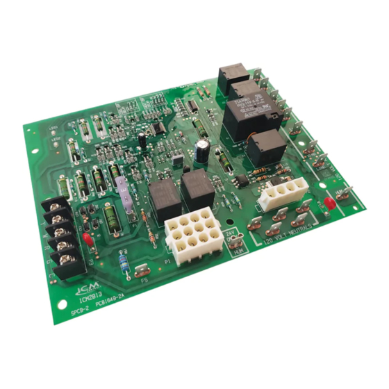
Integrated Furnace Control Board
INTRODUCTION AND OPERATION
The ICM2813 is a form, fit, and functional replacement for the
Lennox and White Rodgers boards shown in the cross reference
section of this guide. The ICM2813 automated gas ignition
control board monitors the ignition sequence including the
inducer, pressure switch, hot surface igniter, gas valve, flame
sense, and circulating blower while maintaining full safety circuit
monitoring including the high limit switch, roll out switch and
auxiliary limit switch circuits. Onboard diagnostics will indicate
when a fault condition exists.
SPECIFICATIONS
• Electrical Rating @ 77°F (25°C)
• Input Voltage: 18-30 VAC, 60 Hz
• Ignitor Current: 2.0 amp @ 80 VAC, 60 Hz (resistive)
• Inducer Relay: 2.2 FLA–3.5 LRA @ 120 VAC
• Blower Relay: 9.5 FLA–25.0 LRA @ 120 VAC (Heat / Cool / Fan)
• Gas Valve Relay: 1.5 amp @ 25 VAC, 60 Hz 0.6 pf
Environmental
• Operating Temp Range: -40° to 176°F (-40° to 80°C)
• Humidity Range: 5 to 95% relative humidity (non-condensing)
REMOVE EXISTING CONTROL
To service control, and prior to disconnection,
CAUTION
label all wires. Failure to do so may result in
wiring errors which can cause dangerous operation.
1. Turn thermostat to OFF position or set it to the lowest
possible setting.
2. Turn OFF electrical supply to furnace.
3. Turn OFF gas supply to furnace.
4. Remove furnace blower and control access doors.
5. Remove control box cover.
Failure to turn off gas and electric supplies can
CAUTION
result in explosion, fire,death, or personal injury.
6. Disconnect thermostat wires and humidifier wires (if
equipped with a humidifier).
7. Disconnect line voltage, blower, electronic air cleaner wires
(if equipped), and transformer wires.
8. Remove wiring harness from circuit board.
9. Remove screws or any other fasteners and old circuit board.
10. Examine control and control box to check for water stains.
11. Make repairs if any sources of water leakage are found.
Be sure to check humidifiers, evaporator coils, and vent
systems in the area of the control.
ICM2813
Advertisement
Table of Contents

Summary of Contents for ICM Controls ICM2813
- Page 1 INTRODUCTION AND OPERATION The ICM2813 is a form, fit, and functional replacement for the Lennox and White Rodgers boards shown in the cross reference section of this guide. The ICM2813 automated gas ignition...
- Page 2 At the end of the OFF delay, the cool blower and EAC are turned off. HEAT BLOWER JUMPER SETTINGS INSTALL NEW CONTROL 1. Ground yourself properly before installing the new ICM2813 Time control board. 1 - 2 180 seconds 2.
-
Page 3: Wire Harness Connections
1. Plug 12-pin wiring harness supplied with the ICM2813 board into Figure 3 the 12 pin socket on the ICM2813 board as seen in Figure 3 location 1. It is a keyed connector and only connects one way. There are 3 wires which have ¼... -
Page 4: Led Fault Codes
FLAME SENSE TROUBLESHOOTING TIPS LED FAULT CODES Flame not established 1. If the flame is not established or proven during the initial Status Description Trouble Shooting Tips sequence, the gas is shut off (if energized) and the board Normal will enter a retry mode. There will be four more successive Operation attempts allowed each having a 15 second inducer purge Check for proper input voltage and... -
Page 5: Wiring Diagram
P2 Plug Pin Out XFRM 1 = Inducer blower LINE 2 = Hot surface ignitor 3 = Neutral 4 = Neutral ONLY Legend ICM2813 120 VOLT NEUTRALS = Electronic air cleaner Flame Sensor = Flame sensor GND = Ground INDUCED NEUTRAL DRAFT...
Need help?
Do you have a question about the ICM2813 and is the answer not in the manual?
Questions and answers