Advertisement
- 1 Introduction
- 2 Specifications
- 3 ICM325HN Typical Installation
- 4 Connections for ICM325HN at 120/208/240 VAC
- 5 Connections for ICM325HN at 480 VAC
- 6 Connecting the Probe
- 7 Connections for Air Conditioning Only
- 8 Connections for Heat Pump Systems
- 9 Mode of Operation
- 10 Setting the Cutout Speed
- 11 Setting the Hard Start Time
- 12 Troubleshooting
- 13 Documents / Resources
Introduction

Installation of the ICM325HN shall be performed by trained technicians only. Adhere to all local and national electric codes.
Disconnect all power to the system before making any connections.
Specifications
- Line voltage: 120, 208, 240, and 480 VAC
- Control voltage: 18-30 VAC
- Frequency: 50-60 Hz
- Operating temperature: -40ºF to +176ºF (-40°C to +75°C)
- Sensors: 10K ohms at 77°F (25°C)
- Heat pump override: 24 VAC N.C. or N.O.
![warning]() Note: A maximum of three sensors can be connected to the control.
Note: A maximum of three sensors can be connected to the control. - Weight: 12 ounces (341 grams)
![warning]() Note: The ICM325HN should be applied to motors and equipment that have been designated by their respective manufacturers as capable of being speed controlled.
Note: The ICM325HN should be applied to motors and equipment that have been designated by their respective manufacturers as capable of being speed controlled. - Mounting:
- Surface mount using (4) #8 screws
- The ICM325HN should be surface mounted to a clean metal or other thermally conductive surface for maximum heat dissipation
- It is recommended that the ICM325HN be mounted away from the condenser exhaust air in order to maintain lower operating temperatures
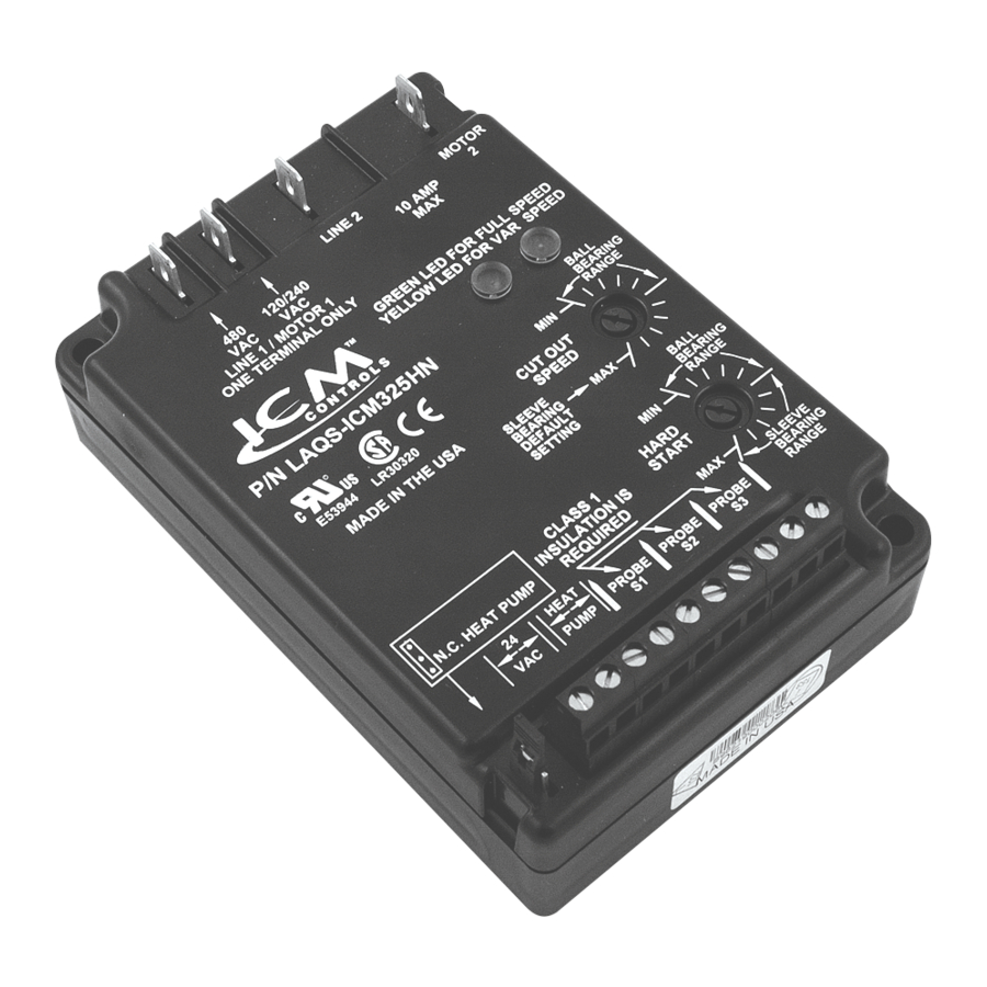
ICM325HN Typical Installation

Connections for ICM325HN at 120/208/240 VAC
- Remove power from system.
- Field install a wire from Line 1 wire to Line 1 terminal.
- Cut Line 2 wire; affix motor side to Motor 2 terminal and line side to Line 2 terminal.
- Make 24 VAC, probe and HP connections.
- Verify wiring is correct.
- Power up system and check operation.
Typical condenser fan

Typical condenser fan with ICM325HN installed

Connections for ICM325HN at 480 VAC
- Remove power from system.
- Field install a wire from Line 1 wire to Line 1 terminal.
- Cut Line 2 wire; affix motor side to Motor 2 terminal and line side to Line 2 terminal.
- Make 24 VAC, probe and HP connections.
- Verify wiring is correct.
- Power up system and check operation.
Typical condenser fan

Typical condenser fan with ICM325HN installed

Connecting the Probe

- Install the temperature probe several bends into the condenser. It can be attached to the U-bend or placed between the fins in the upper 1/3 of the condenser (see other side for more information).
![warning]() Note: The response of the system can be fine tuned by repositioning the probe. Place the probe on the condenser where it is 100°F when pressures are correct for best response.
Note: The response of the system can be fine tuned by repositioning the probe. Place the probe on the condenser where it is 100°F when pressures are correct for best response. - Connect the two wires from the sensor to the terminal block where it is marked PROBE S1. If additional probes are necessary for multiple refrigerant circuits, they may be attached to terminals marked PROBE S2 and PROBE S3.
![warning]() Note: The control will respond to the probe that senses the highest temperature.
Note: The control will respond to the probe that senses the highest temperature.
Connections for Air Conditioning Only

- For non-heat pump applications, the heat pump select jumper must be in the Default (N.O.) position, and the HP terminals must be left unconnected.
- Set the Cutout Speed and the Hard Start Time to the appropriate positions for the type of motor you have (see other side).
Connections for Heat Pump Systems
- The Heat Pump terminals accept the 24 VAC signal from the reversing valve holding coil. Make a parallel connection from the reversing valve to the HP terminals.
![warning]() Note: Do not apply a voltage higher than 30 VAC to the HP terminals.
Note: Do not apply a voltage higher than 30 VAC to the HP terminals. - If the Heat Pump is in the Heating mode and the reversing valve is energized, then the Heat Pump Select jumper must be in the Default (N.O.) position.
![]()
- If the Heat Pump is in the Heating mode and the reversing valve is not energized, then the Heat Pump Select jumper must be in the N.C. position.


Mode of Operation
Normal Function
With probe temperatures above 100°F, the control applies full voltage to the motor. The green light is illuminated (full speed LED).
With probe temperatures between 70°F and 100°F, the motor speed is proportional to the probe temperature. The yellow light is illuminated (variable speed LED).
When the motor starts at temperatures between 70°F and 100°F, it will hard start for the length of time dictated by the hard start dial setting. After the hard start time has elapsed, the motor speed is controlled by the probe temperature.
As the temperature being sensed decreases, the output voltage decreases. The output voltage may decrease to the determined cutout speed dictated by the cutout speed dial. Upon reaching the cutout speed setting, the output voltage goes to zero volts.
System restart will occur when the temperature exceeds 70°F.
With probe temperatures below 70°F, the motor remains off. The green light and the yellow light are off.
Heat Pump Bypass Operation
Heat pump bypass mode runs the fan at full speed when the system is operating in heat mode. This moves as much air as possible across the condenser coil.
If the heat pump select jumper is in the N.O. position, and 24 VAC is applied to the HP terminals, the motor will be brought to full speed.
If the heat pump select jumper is in the N.C. position, and 24 VAC is not present at the HP terminals, the motor will be brought to full speed.
A separate relay is not needed.
Setting the Cutout Speed

The cutout speed dial adjusts the motor voltage range. Set the cutout voltage dial according to the type of motor you have.
Sleeve Bearing Motors
Set the cutout speed dial to the middle of the sleeve bearing range. In this range, the motor can run down approximately 40-50% of the full line voltage, which allows sufficient RPMs for cooling and lubrication.
With sleeve bearing motors, it is important not to adjust outside the sleeve bearing range or bearing failure may result.
Ball Bearing Motors
Set the cutout speed dial to the MIN position in the ball bearing range. This position offers the greatest range of speed control. At the MIN setting the motor can run down to approximately 20-30% of the full line voltage.
 Note: After starting at the recommended settings for either sleeve or ball bearing motors, you can fine tune the cutout speed to achieve the desired results.
Setting the Hard Start Time

During the Hard Start mode, full voltage is applied to the motor during startup to overcome windmilling and to lubricate the bearings.
The position of the hard start dial determines the time period of the hard start mode.
The dial can be adjusted between 0.1 second and approximately 5 seconds.
Set the hard start dial according to the type of motor you have. If you have a ball bearing motor, set the hard start dial to the MIN position. If you have a sleeve bearing motor, set the hard start dial to the middle of the sleeve bearing range.
After you begin at the recommended setting, you can fine tune the hard start time within the recommended range for the type of motor you have.
It is recommended that you use the minimum possible hard start time to avoid blowing too much cold air over the condenser.
Hard Start mode is activated when 24 VAC is applied (or disconnected and re-applied) or the probe temperature increases to above 70°F. The hard start mode applies full voltage to the motor for the set time period. Afterwards, the motor speed is dictated by the temperature sensor(s).
Troubleshooting
| Symptom | Problem | |||
| Unit fails to start | The sensor may not be connected or it is defective. With the probe disconnected, use an ohmmeter to measure the resistance between the probe wires. It should match the chart in "Temperature vs. Probe Resistance" (see below). If you read an OPEN or SHORT, replace the sensor. | |||
| Fuse and/or circuit blows | The unit has been miswired and may be permanently damaged. | |||
| The fan cycles from full ON to full OFF with little or no modulation | Turn OFF the control circuit power (24 VAC). Re-apply 24 VAC power and confirm hard start operation. Reduce the hard start period to the minimum setting required to accelerate the fan. Excessive hard starting causes large pressure drops by running too much cold air over the condenser. Should the cycling persist, move the probe up several bends into the condenser to increase the sensitivity to condensing temperature. Adjust probe location. Fine tune cutout adjustment. | |||
| The fan does not come on at all | Using an AC voltmeter, measure the voltage between the 24 VAC terminals. It should read approximately 24 volts. Measure the line voltage between LINE 1 and LINE 2 to confirm that the line voltage is present. Remove the thermistor probe from the terminal block and measure its resistance at ambient temperature. Compare your reading at the appropriate temperature in "Temperature vs. Probe Resistance" to see if the actual resistance approximates the listed value. Next, hold the probe in your hand and confirm that the resistance decreases. Place a temporary jumper across the S2 or S3 terminals. Fan should run at full speed. If it does, recheck probe connection and verify probe is operating correctly. | |||
| The high pressure switch trips off | Move the probe further into the condenser where the temperature is higher. This will produce a higher fan RPM and will decrease the head pressure. Fine adjust the cutout and hard start settings. | |||
| Green and yellow LEDs alternate | Using an AC voltage meter, measure the voltage between the 24 VAC terminals. Also verify you have the voltage between Line 1 and LINE 2 terminals. | |||
Mounting a sensor into the condenser vs. mounting it on the liquid line
When a sensor is mounted into the condenser, the control responds more rapidly to changes in head pressure than when it is mounted on the liquid line. This is especially true for high efficiency condensers.
When the sensor is mounted on the liquid line, the control responds more slowly and the results can be a fan that cycles on and off.
Whenever possible, it is preferable to mount the sensor in the upper 1/3 of the condenser instead of mounting it on the liquid line (see illustration below). A spot on the condenser that is 100F when the pressures are correct is ideal.
Temperature vs. Probe Resistance
| °C | °F | Resistance (KΩ) |
| 0° | 32° | 32.7 |
| 5° | 41° | 25.4 |
| 10° | 50° | 19.9 |
| 15° | 59° | 15.7 |
| 20° | 68° | 12.5 |
| 25° | 77° | 10.0 |
| 30° | 86° | 8.1 |
| 35° | 95° | 6.5 |
| 40° | 104° | 5.3 |
| 45° | 113° | 4.4 |
| 50° | 122° | 3.6 |
For more information on our complete range of American-made products – plus wiring diagrams, troubleshooting tips and more, visit us at www.icmcontrols.com

Documents / Resources
References
Download manual
Here you can download full pdf version of manual, it may contain additional safety instructions, warranty information, FCC rules, etc.
Download ICM Controls ICM325HN - Head Pressure Control Manual
Advertisement


Need help?
Do you have a question about the ICM325HN and is the answer not in the manual?
Questions and answers