Table of Contents
Advertisement
Quick Links
FEATURES
• Direct Spark Ignition (DSI) control board
• Microprocessor-based
• Controls inducer motors, air cleaner (if equipped), humidifier
(if equipped), spark ignitor and the gas valve
• Monitors timing, trial for ignition, system switches, flame sensing
and lockout
• 100% lockout safety feature
• Compatible with LP or natural gas
• LED indication for status and fault codes to aid in troubleshooting
• Replaces: Rheem 62-24140-04
Safety Considerations
Only trained personnel should install or service heating equipment. When working with heating
equipment, be sure to read and understand all precautions in the documentation, on labels, and on
tags that accompany the equipment. Failure to follow all safety guidelines may result in damage to
equipment, severe personal injury or death.
Introduction
The ICM292A DSI gas ignition control replaces the following Rheem model: 62-24140-04. The
ICM292A has incorporated LED diagnostics to assist in troubleshooting. Fault code information can
be found in this application guide. Please keep this application guide with the furnace installation
manual for future reference.
Electrostatic Discharge (ESD) Precautions
CAUTION!
Use caution when installing and servicing the furnace to avoid and control electrostatic discharge;
ESD can impact electronic components. These precautions must be followed to prevent
electrostatic discharge from hand tools and personnel. Following the precautions will protect the
control from ESD by discharging static electricity buildup to ground.
1. Disconnect all power to the furnace. Do not touch the control or the wiring prior to discharging your
body's electrostatic charge to ground.
2. To ground yourself, touch your hand and tools to a clean, metal (unpainted) furnace surface near
the control board.
3. Service the furnace after touching the chassis. Your body will recharge with static electricity as you
shuffle your feet or move around, and you must reground yourself.
4. Reground yourself if you touch ungrounded items.
5. Before handling a new control, reground yourself; this will protect the control. Store used and new
controls in separate containers before touching ungrounded objects.
6. ESD damage can also be prevented by using an ESD service kit.
Remove Existing Control
CAUTION!
To service control, and prior to disconnection, label all wires. Failure to do so may result in wiring
errors that can cause dangerous operation.
1. Turn thermostat to OFF position or set it to the lowest possible setting.
2. Turn OFF electrical supply to furnace.
3. Turn OFF gas supply to furnace.
CAUTION: Failure to turn off gas and electric supplies can result in explosion, fire, death, or
personal injury.
4. Remove furnace blower and control access doors.
5. Disconnect thermostat wires and humidifier wires (if equipped with a humidifier).
6. Disconnect line voltage, blower, electronic air cleaner wires (if equipped), and transformer wires.
7. Remove screws and any other fasteners, and the old circuit board.
8. Examine control and control box to check for water stains.
9. Make repairs if any sources of water leakage are found. Be sure to check humidifiers, evaporator
coils, and vent systems in the area of the control.
Install New Control
1. Ground yourself. When handling circuit board, hold it by the edges.
2. Fasten circuit board with retaining screws.
3. Connect all line voltage, low voltage, and accessory wires.
4. Verify the sequence of operation.
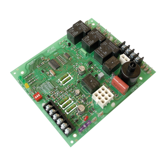
ICM292A Gas Ignition Control Board
SPECIFICATIONS
• Control voltage: 24 VAC (18-30 VAC), 60 Hz
• Line voltage: 115 VAC, 60 Hz
• Power consumption: 0.3A plus gas valve current at 24 VAC
• Operating temperature: -40°C (-40°F) to 75°C (176°F)
Timing
• Pre-purge: 30 seconds
• Trial for ignition: 7 seconds
• Retries: Two groups of two, 30 seconds delay within
the group and 3 minutes delay between
groups
• Lockout: 1 hour
• Post-purge: 90, 120, 160 and 180 seconds
Inputs
• Power: 24 VAC and COM
• Thermostat interface: R, W, Y and G
• System switches: Vent pressure and limit switches
(main and over-temperature switches in series)
• Flame Sensing
• Heat blower OFF delay: SW1 toggle switch
Sequence of Operation
A W call from the thermostat will engage the Inducer Draft motor. The Vent Pressure switch closes.
Ignition sequence begins, gas valve and spark are engaged, providing that system safety switches
(Main and Over-temperature switches in series) are closed. The Blower motor will engage at HEAT
speed 20 seconds after flame is established and sensed. On W call satisfaction, the Inducer motor
turns off after 10 seconds and Blower motor turns off according to Heat Blower Off delay setting.
A G call from the thermostat will engage Blower motor without delay at FAN speed. It disengages
without delay when G call is removed.
A Y call from the thermostat will engage Blower motor without delay at COOL speed. It disengages
45 seconds after Y call is satisfied.
Troubleshooting Tips
Flame not established
1. If flame is not established during the 7 second initial sequence then the control will start the next
trial for ignition in 30 seconds.
2. There will be two more attempts to ignite after 3 minute delay, 30 seconds apart before the
respective fault code is triggered and ignition trials are stopped.
3. The gas valve is energized only during the ignition sequence of 7 seconds.
4. Blower motor is off until 20 seconds after flame is established.
Flame out
1. Flame out is considered when flame is lost during heating.
2. When W signal is present and flame is not sensed, then gas valve will disengage until the next trial
for ignition
3. If flame is not established on the immediate sequence (2 above) then the control will continue with
additional trials for ignition
4. Inducer and Blower motors will continue running during flame out scenario
Flame out of sequence
1. Flame out of sequence represents a scenario when flame is sensed while W signal is not present.
2. Inducer and Blower motors will be engaged (if not already running) and keep running for as long as
the fault condition is present.
3. There is 1 hour lockout before a W call can be executed or on power reset
LED Fault Codes
LEDS
Flashes
ON
GREEN
1 Flash
2 Flashes
3 Flashes
4 Flashes
5 Flashes
6 Flashes
7 Flashes
Continuous
Rapid Blink
YELLOW
Slow Blink
ON
Outputs
• Gas Valve:
3A Pilot Duty @ 120 VAC
• Draft Inducer Motor:
3A max., 1/6HP @ 125 VAC
• Cool Blower:
16A max., 1/2HP @ 277 VAC
• Heat Blower:
14A max., 1/2HP @ 277 VAC
• Circulating Fan:
12A max., 1 HP @ 125 VAC
• Heat/Cool Fan:
10 A max., 1/2 HP @ 277 VAC
• Electronic Air Cleaner:
10 A max., 1HP @ 125 VAC
• Humidifier:
11 A max., 1/6HP @ 125 VAC
LED indicators
• Power, green LED: PWR
• Status, green LED: OK
• Flame status, yellow LED: FLAME
Fault condition
Normal operation
Ignition failure (4 trials)
Pressure switch stuck open
Limit switches open
Pressure switch stuck closed
Twin fault
Brownout voltage
Hot and neutral reversed or no ground
Gas valve relay short
Flame out of sequence
Low flame or no flame
Flame present
LIAF294-1
Advertisement
Table of Contents

Subscribe to Our Youtube Channel
Related Manuals for ICM Controls ICM292A


Summary of Contents for ICM Controls ICM292A
- Page 1 A G call from the thermostat will engage Blower motor without delay at FAN speed. It disengages without delay when G call is removed. The ICM292A DSI gas ignition control replaces the following Rheem model: 62-24140-04. The ICM292A has incorporated LED diagnostics to assist in troubleshooting. Fault code information can A Y call from the thermostat will engage Blower motor without delay at COOL speed.
Need help?
Do you have a question about the ICM292A and is the answer not in the manual?
Questions and answers