Table of Contents
Advertisement
Quick Links
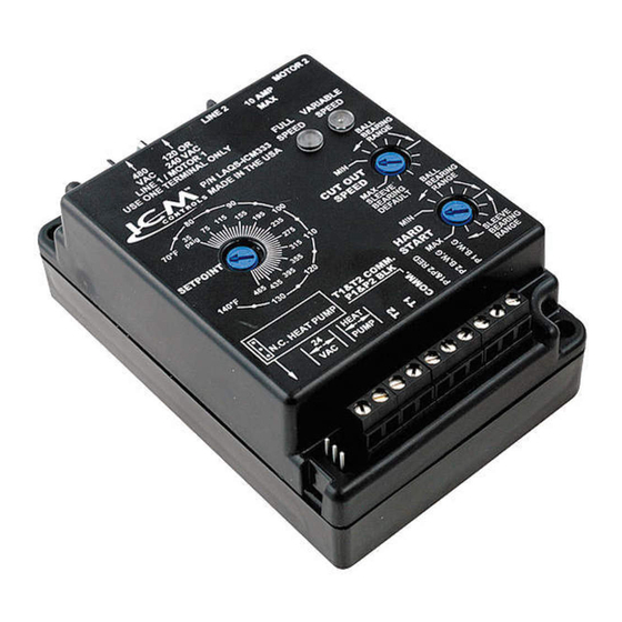
ICM333
Head Pressure Control with
Optional Heat Pump Override
Regulates head pressure via
temperature or pressure input
Installation, Operation & Application Guide
For more information on our complete range of American-made
products – plus wiring diagrams, troubleshooting tips and more,
visit us at www.icmcontrols.com
Installation of the ICM333 shall be performed by trained technicians only. Adhere to all local and national electric codes. Disconnect all power to the system before making any connections.
• Line voltage: 120, 208, 240, 277, 480 and 600 VAC
• Control voltage: 18-30 VAC
• Frequency: 50-60 Hz
• Operating temperature: -40ºF to +176ºF (-40°C to +75°C)
• Probes: – Temperature: Thermistor, 10K ohm at 77°F (25°C)
– Pressure: ICM380 (ordered separately)
• Heat pump override: 24 VAC N.C. or N.O.
• Weight: 12 ounces (341 grams)
Connections for ICM333 at 120/208/240/277 VAC
1. Remove power from system.
2. Field install a wire from Line 1 wire to Line 1 terminal.
3. Cut Line 2 wire; affix motor side to Motor 2 terminal
and line side to Line 2 terminal.
4. Make 24 VAC and temperature probe connections.
5. Verify wiring is correct.
6. Power up system and check operation.
120/208/240/277
Field
Installed
Wire
120/277
Connections for ICM333 at 480/600 VAC
1. Remove power from system.
2. Field install a wire from Line 1 wire to Line 1 terminal.
3. Cut Line 2 wire; affix motor side to Motor 2 terminal
and line side to Line 2 terminal.
4. Make 24 VAC and temperature probe connections.
5. Verify wiring is correct.
6. Power up system and check operation.
Field
Installed
Wire
Line
1
1. Only one probe type can be used at a time, temperature or pressure. Up to two
probes of a kind can be used in which case the control will respond to the probe
that senses the highest temperature or pressure.
2. A typical installation is shown in Appendix. The temperature probe can be
attached to the U-bend. Use the provided thermo-tape to secure the probe to the
place of attachment.
3. When using a pressure probe, install it on the discharge line transducer fitting.
4. Temperature and Pressure probes are connected to ICM333 as shown in
respective wiring diagrams below.
120/208/240/277
Run
VAC
Capacitor
Typical
condenser fan
VAC
Run
Capacitor
Line
Line
Motor
1
2
2
VAC
Run
Capacitor
Typical
condenser fan
Run
Capacitor
Line
Motor
2
2
Installing and Connecting the Probe
The Seller warrants its products against defects in material or workmanship for a period of one (1)
year from the date of manufacture. The liability of the Seller is limited, at its option, to repair, replace
or issue a non-case credit for the purchase prices of the goods which are provided to be defective.
The warranty and remedies set forth herein do not apply to any goods or parts thereof which have
been subjected to misuse including any use or application in violation of the Seller's instructions,
neglect, tampering, improper storage, incorrect installation or servicing not performed by the Seller.
In order to permit the Seller to properly administer the warranty, the Buyer shall: 1) Notify the Seller
promptly of any claim, submitting date code information or any other pertinent data as requested by
the Seller. 2) Permit the Seller to inspect and test the product claimed to be defective. Items claimed
to be defective and are determined by Seller to be non-defective are subject to a $30.00 per hour
inspection fee. This warranty constitutes the Seller's sole liability hereunder and is in lieu of any other
warranty expressed, implied or statutory. Unless otherwise stated in writing, Seller makes no warranty
that the goods depicted or described herein are fit for any particular purpose.
(Toll Free) 800-365-5525
Caution!
Specifications
Note: The ICM333 should be applied to motors and equipment that have been designated by their
respective manufacturers as capable of being speed controlled.
• Mounting:
– Surface mount using (2) #8 screws
– The ICM333 should be surface mounted to a clean metal or other thermally conductive surface
for maximum heat dissipation
– It is recommended that the ICM333 be mounted away from the condenser exhaust air in order to
maintain lower operating temperatures
Connections for Heat Pump System at 120/208/240/277 VAC
1. Remove power from system.
2. Field install a wire from Line 1 wire to Line 1 terminal.
3. Cut Line 2 wire; affix the common from the defrost
PSC
board's fan relay to the Motor 2 terminal and the Line
Fan
from the contactor to the Line 2 terminal.
Motor
PSC
Fan
Motor
Connections for Heat Pump System at 480/600 VAC
1. Remove power from system.
2. Field install a wire from Line 1 wire to Line 1 terminal.
3. Cut Line 2 wire; affix the common from the defrost
PSC
board's fan relay to the Motor 2 terminal and the Line
Fan
from the contactor to the Line 2 terminal.
Motor
PSC
Fan
Motor
TEMPERATURE
PROBE 1
TEMPERATURE
PROBE 2
ONE-YEAR LIMITED WARRANTY
7313 William Barry Blvd., North Syracuse, NY 13212
(Phone) 315-233-5266
www.icmcontrols.com
4. Make 24 VAC, probe and HP connections.
5. Verify wiring is correct.
6. Power up system and check operation.
120/208/240/277
VAC
Field
Installed
Wire
Line
Line
Motor
1
2
2
120/240/277
VAC
4. Make 24 VAC, probe and HP connections.
5. Verify wiring is correct.
6. Power up system and check operation.
Field
Installed
Wire
Line
Line
Motor
1
2
2
PRESSURE TRANSDUCER
2
PRESSURE TRANSDUCER
1
(Fax) 315-233-5276
LIAF010-1
Fan
Relay
COM
NC
Defrost Board
Run
Capacitor
PSC
Fan
Motor
Fan
Relay
COM
NC
Defrost Board
Run
Capacitor
PSC
Fan
Motor
Example
Advertisement
Table of Contents

Subscribe to Our Youtube Channel
Related Manuals for ICM Controls ICM333


Summary of Contents for ICM Controls ICM333
- Page 1 LIAF010-1 Caution! Installation of the ICM333 shall be performed by trained technicians only. Adhere to all local and national electric codes. Disconnect all power to the system before making any connections. Specifications • Line voltage: 120, 208, 240, 277, 480 and 600 VAC Note: The ICM333 should be applied to motors and equipment that have been designated by their respective manufacturers as capable of being speed controlled.
- Page 2 19.9 15° 59° 15.7 20° 68° 12.5 25° 77° 10.0 30° 86° 35° 95° 40° 104° 45° 113° 50° 122° ICM333 Typical Installation Motor Condenser Line Voltage Line 1 Line 2 Motor Terminal to be used for 480/600 VAC Control Transformer ICM333 Reversing Valve for Heat Pump can monitor two condensers T-Stat...
Need help?
Do you have a question about the ICM333 and is the answer not in the manual?
Questions and answers