Table of Contents

Subscribe to Our Youtube Channel
Related Manuals for Keithley S500


Summary of Contents for Keithley S500
- Page 1 99 Washington Street Melrose, MA 02176 Phone 781-665-1400 Toll Free 1-800-517-8431 Visit us at www.TestEquipmentDepot.com S500 Administrative Guide PA-939 Rev. B / October 2007 G R E A T E R M E A S U R E C O N F I D E N C E...
- Page 2 This page left blank intentionally . Test Equipment Depot - 800.517.8431 - 99 Washington Street Melrose, MA 02176 - TestEquipmentDepot.com...
- Page 3 WARRANTY Keithley Instruments, Inc. warrants this product to be free from defects in material and workmanship for a period of one (1) year from date of shipment. Keithley Instruments, Inc. warrants the following items for 90 days from the date of shipment: probes, cables, software, rechargeable batteries, diskettes, and documentation.
- Page 4 This page left blank intentionally . Test Equipment Depot - 800.517.8431 - 99 Washington Street Melrose, MA 02176 - TestEquipmentDepot.com...
- Page 5 ALWAYS remove power from the entire test Keithley Instruments products are designed for use with system and discharge any capacitors before: connecting or electrical signals that are rated Measurement Category I and...
- Page 6 WARNING! they are equivalent to the original component (note that DO NOT SWING TEST HEAD TO POSI- selected parts should be purchased only through Keithley TION INDICATED. UNIT COULD TOPPLE. Instruments to maintain accuracy and functionality of the product). If you are unsure about the applicability of a...
-
Page 7: Table Of Contents
Table of contents I. System Description ..............................1 II. Equipment Startup ..............................3 Emergency Off (EMO) button............................3 III. Maintenance ................................3 Hardware Replacement.............................3 Handling and cleaning precautions ...........................3 Electrical hazard tasks ..............................4 Heavy instrument removal/installation ........................4 Power distribution and EMO............................6 A. Site Preparation & Installation ..........................9 System cabinet size and weight..........................9 Line power requirements............................10 System Power Dissipation............................10... - Page 8 S500 Administrative Guide PA-939 Rev. B / October 2007 Test Equipment Depot - 800.517.8431 - 99 Washington Street Melrose, MA 02176 - TestEquipmentDepot.com...
-
Page 9: System Description
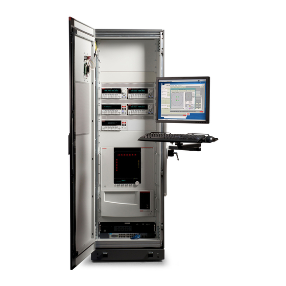
I. System Description The S500 is an instrument based system configuration from Keithley Instruments primarily for semiconductor parametric characterization testing. The system has a wide degree of hardware flexibility enabling users to configure systems better suited for their applications. The table below and Figure 1 describe the configuration details for the system. - Page 10 3. Users can also develop and manage their own system software. Keithley Instruments can also supply various cables that interface to test fixtures such as wafer probers as well as a probe card adaptor (PCA). Figure 1...
-
Page 11: Equipment Startup
II. Equipment Startup All of the instruments in the equipment rack will be connected to one or two PDUs (Power Distribution Units) depending on configuration. They will be located at the bottom of the rack. If there are two, they will be mounted back to back so that one would be located at the front of the cabinet and one at the back of the cabinet. -
Page 12: Electrical Hazard Tasks
When servicing any component, wear clean cotton gloves. If making solder repairs on a circuit board, use an OA-based (organically activated) flux. Remove the flux from the work areas when the repair is complete. Use pure water along with plenty of clean cotton swabs or a clean soft brush to remove the flux. - Page 13 5. Place the main circuit breaker on the power distribution unit(s) in the OFF position. 6. Disconnect the source power to the S500 system (1 or 2 power cords dependant on system configuration). 7. Place the locks and tags on the source power connection, main circuit breaker, power switch, and EMO button.
-
Page 14: Power Distribution And Emo
Refer to the applicable manual that is included with the product for fuse replacement. Power distribution and EMO System cabinet power distribution basics Figure 3 contains simplified connection schematics for the various components of the S500. Test Equipment Depot - 800.517.8431 - 99 Washington Street Melrose, MA 02176 - TestEquipmentDepot.com... - Page 15 Properly ground the 42000-PDU to avoid possible personal injury or death caused by electric shock. The connection schematic contained in Figure 4 provides power to the S500 cabinet fans. Figure 4 and Table 2 provide a detailed description of the available connections. Information on the EMO circuit's connection and operation is also provided.
- Page 16 Table 2 Connection descriptions Item Connection Description Specially Switched Outlets Two power outlets located on the PDU’s rear panel. Do not use power outlets for accessories (e.g., soldering iron, drill, etc.). Use for instruments that do NOT have hazardous voltages and don’t need to have power removed through the EMO circuit (e.g., a computer).
-
Page 17: Site Preparation & Installation
Figure 4 42000-PDU simplified schematic A. Site Preparation & Installation System cabinet size and weight The size and weight specifications for the system cabinet are listed in Table 3. See “Floor plan” for details on designing a floor plan for the system cabinet. Table 3 System cabinet size and weight Weight... -
Page 18: Line Power Requirements
This applies to the S500 only. The total power dissipated by the S500 is a function of the type and number of instruments; however, the power distribution unit (PDU) limits the incoming power to these instruments. While the PDU ensures electrical safety and compliance to the required standards, it does not prevent the system from over heating. -
Page 19: Triax Connector Handling (Contamination)
S500 Administrative Guide Triax connector handling (contamination) Contamination can cause current leakage in the source-measure signal paths to the DUT. Leakage current can significantly degrade the test results. Care must be taken to keep source-measure triax cable connectors (if applicable) clean and free of any foreign contaminants. DO NOT touch the connector pins of the triax connectors. -
Page 20: Installation And Connections
NOTE Larger S500 systems may have two Model 42000-PDU line cords. Plug each PDU line cord into a separate 15A or 20A circuit depending type of system. Position the system cabinet The system cabinet contains the controller and instrumentation for the test system. -
Page 21: Floor Plan
9ft x 10ft (2.7m x 3m). Figure 5 shows a top view of the floor plan. Table 3, in the “Site Preparation & Installation” section of this guide, lists the dimensions and weight of the system cabinet. Figure 5 S500 floor plan – top view 62.1 in (1577 mm) 38.1 in... -
Page 22: Seismic Securement
Seismic securement Typical S500 system cabinet weight distribution and center of gravity are shown in Figure 6. If seismic se curement is required, the system cabinet can be bolted down to the floor. Figure 7 shows the restraint brackets and bolt installation dimensions for the system cabinet. -
Page 23: Specifications
S500 Administrative Guide Figure 7 Seismic system cabinet restraints Figure 8 Floor mounting bracket installation B. Specifications Refer to individual instrument documentation and specifications. PA-939 Rev. B / October 2007 Test Equipment Depot - 800.517.8431 - 99 Washington Street Melrose, MA 02176 - TestEquipmentDepot.com... - Page 24 Service Form Model No. Serial No. Date Name and Telephone No. Company List all control settings, describe problem and check boxes that apply to problem. ❏ ❏ ❏ Intermittent Analog output follows display Particular range or function bad; specify ❏ ❏...
- Page 25 This page left blank intentionally . Test Equipment Depot - 800.517.8431 - 99 Washington Street Melrose, MA 02176 - TestEquipmentDepot.com...
- Page 26 C O N F I D E N C E Keithley Instruments, Inc. Corporate Headquarters • 28775 Aurora Road • Cleveland, Ohio 44139 • 440-248-0400 • Fax: 440-248-6168 • 1-888-KEITHLEY • www.keithley.com 12/06 Test Equipment Depot - 800.517.8431 - 99 Washington Street Melrose, MA 02176 - TestEquipmentDepot.com...
Need help?
Do you have a question about the S500 and is the answer not in the manual?
Questions and answers