Advertisement
Available languages
Available languages
Quick Links
Advertisement

Related Manuals for Timken ROLLON R-Smart Series


Summary of Contents for Timken ROLLON R-Smart Series
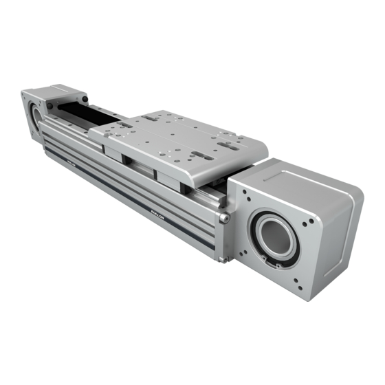
- Page 1 Smart System Actuator Line Smart system R-Smart Use and maintenance...
- Page 3 Content Use and maintenance Lubrication, Preliminary operations UM-2 Driving belt replacement, Head removing, Sliding block replacement UM-3 Gearbox assembly UM-4 Components UM-5 Warning and legal notes UM-6 Uso e manutenzione Ingrassaggio, Operazioni preliminari UM-10 Sostituzione cinghia di trazione, Rimozione della testata, Sostituzione pattini UM-11 Montaggio del riduttore UM-12...
- Page 4 R-SMART Use and maintenance Lubrication Insert the tip of the grease gun in the specific grease blocks soap grease of class No. 2. For specially stressed applications (Fig. 1). Repeat this operation every 2000 km or 1 year of use or difficult environmental conditions, lubrication should be based on the value reached first.
- Page 5 Smart System Driving belt replacement First of all carry out the operations indicated at the points 1 - 2 for both ends of the carriage 3) Remove the drive belt from both ends of the carriage (Fig. 5) and pull off (Fig. 6). To re-assemble the belt, carry out the same operations in the opposite way repositioning the belt tensioner at the initial distance X.
- Page 6 R-SMART Gearbox assembly Tightening sequence of the shrink disc screws: Place the axis as shown in the figure with the gear assem- ■ ■ bly component facing upwards. Tighten the two diametrically opposite screws until the ■ Assemble the flange (1) on the gear and tighten the screws surfaces are in contact with the shaft and hub.
- Page 7 Smart System RIGHT POSITION OF THE ELEMENTS IT IS FORBIDDEN IT IS NOT TO ASSEMBLE THE RECOMMENDED RINGS WITH THE TO ASSEMBLE THE THREADS ALIGNED RINGS WITH THE CUTS ALIGNED In the image below are reported the correct angle positions of the components that build the shrink ring to use only in the case it was dismounted completely.
- Page 8 E-SMART Warnings and legal notes Before incorporating the partly completed machinery, The manufacturer cannot be considered responsible we recommend consulting this chapter carefully, in for any consequences derived from improper use or addition to the assembly manual supplied with the any use other than the purpose the axis or system individual modules.
- Page 9 Smart System Residual risks Mechanical risks due to the presence of moving elements (X, Y Risk of the Z axis dropping during maintenance operations in ■ ■ axes). the case of a drop in the electrical power supply voltage. Risk of fire resulting from the flammability of the belts used on Crushing hazard near moving parts with divergent and ■...
- Page 10 Warnings and legal notes Safety warnings for handling and transport The manufacturer has paid the utmost attention to packaging to Mark and delimit the established location to prevent unauthori- ■ ■ minimize risks related to shipping, handling and transport. zed personnel from accessing the installation area. Transport can be facilitated by shipping certain components The installation site must have adequate environmental condi- ■...
- Page 11 Smart System Transport Transport, also based on the final destination, can be done with ■ different vehicles. Perform transport with suitable devices that have adequate ■ loading capacity. Ensure that the machine and its components are adequately ■ anchored to the vehicle. Handling and lifting Correctly connect the lifting devices to the established points ■...
- Page 12 R-SMART Uso e manutenzione Ingrassaggio Inserire il beccuccio erogatore negli appositi ingrassato- Per applicazioni intense o difficili condizioni ambientali, è ri (Fig. 1). Ripetere le operazioni ogni 2000 km o 1 anno necessaria una lubrificazione più frequente. Per maggiori d’uso in base al valore raggiunto per primo. Tipo di lubri- informazioni rivolgersi a Rollon.
- Page 13 Smart System Sostituzione cinghia di trazione PRIMA DI INIZIARE SVOLGERE LE OPERAZIONI AI PUNTI 1-2-3 4) Liberare la cinghia dalle sedi su entrambi i lati del carro e sfilarla tirando semplicemente (Fig. 6). Per rimontare la cinghia svolgere le stesse operazioni all’inverso, riposizio- nando il serrracinghia alla distanza iniziale X.
- Page 14 R-SMART Montaggio del riduttore Sequenza di serraggio delle viti del calettatore: Posizionare l’asse come da figura, con la parte di montag- ■ ■ gio del riduttore rivolta verso l’alto. Serrare due viti diametralmente opposte sino a che le ■ Montare la flangia (1) sul riduttore serrando le viti (2) con superfici non siano a contatto con l’albero ed il mozzo ■...
- Page 15 Smart System CORRETTO POSIZIONAMENTO DEGLI ELEMENTI VIETATO MONTARE SCONSIGLIATO GLI ANELLI CON I MONTARE GLI FILETTI ALLINEATI ANELLI CON I TAGLI ALLINEATI Nell’immagine a lato vengono riportate le corrette posizioni angolari dei vari componenti che costituiscono il calettatore da utilizzare solo nel caso in cui venga smontato completamente.
- Page 16 Avvertenze e note legali Avvertenze e note legali Si raccomanda, prima dell’incorporazione della quasi mac- Il fabbricante non può essere considerato responsa- china, di consultare il presente paragrafo con attenzione, bile delle conseguenze eventualmente derivanti unitamente al manuale di assemblaggio fornito con i sin- da un utilizzo improprio o diverso da quello per il goli moduli.
- Page 17 Smart System Rischi residui rischi di tipo meccanico per la presenza di elementi mobili (assi Y,Z); rischio di caduta dell’asse Z durante le operazioni di ma- ■ ■ rischio di incendio conseguente alla infiammabilità delle cinghie nutenzione in caso di caduta della tensione di alimentazione ■...
- Page 18 Avvertenze e note legali Avvertenze di sicurezza per movimentazione e trasporto Il costruttore ha posto particolare attenzione all’imballo per tuale, siano resi disponibili. ■ minimizzare i rischi legati alle fasi di spedizione, movimentazione Il responsabile dell’area di insediamento e quello dell’instal- ■...
- Page 19 Smart System Trasporto Il trasporto, anche in funzione del luogo di destinazione, può ■ essere effettuato con mezzi diversi. Effettuare il trasporto con mezzi idonei e di portata adeguata. ■ Assicurarsi che la macchina e i suoi componenti siano adegua- ■...
- Page 20 R-SMART Bedienungs- und Wartungsanleitung Schmierung Die Schmierung erfolgt an den einzelnen Schmiernippeln der Schmiermittel: Lithiumseifenfett der Konsistenzklasse 2. Bei Laufwagen (Abb. 1). Das Schmierintervall beträgt 2000 km hoher Beanspruchung oder kritischen Umgebungsbedingun- gefahrener Weg oder eine Betriebsdauer von 1 Jahr. Dies ist gen sollte die Nachschmierung häufiger erfolgen.
- Page 21 Smart System Zahnriemenwechsel Führen Sie zunächst die unter den Punkten 1 - 2 ange- gebenen Schritte für beide Enden des Laufwagens durch 3) Entfernen Sie den Riemen auf beiden Seiten des Laufwa- gens und ziehen sie diesen heraus. Zur Montage des neu- en Zahnriemens führen sie die vorangegangenen Schritte in umgekehrter Reihenfolge aus (Abb.
- Page 22 R-SMART Getriebemontage Die Achse wie in der Abbildung gezeigt mit der Getriebe- Die Schrauben der Schrumpfscheibe der Reihenfolge: ■ ■ baugruppe nach oben platzieren. Die beiden diametral gegenüberliegenden Schrauben fest- ■ Den Flansch (1) am Getriebe montieren und die Schrau- ziehen, bis die Oberflächen an der Welle und Nabe anliegen ■...
- Page 23 Smart System RICHTIGE POSITION DER ELEMENTE ES IST VERBOTEN, ES WIRD NICHT DIE RINGE MIT EMPFOHLEN, AUSGERICHTETEN DIE RINGE MIT GEWINDEN AUSGERICHTETEN AUSGERICHTETEN SCHNITTEN GEWINDEN ZU MONTIEREN In der Abbildung unten sind die korrekten Winkelpositionen der Komponenten angegeben, aus denen der Schrumpfring besteht, der nur im Falle einer vollständigen Demontage zu verwenden ist.
- Page 24 Warn- und Rechtshinweise Warn- und Rechtshinweise Es wird empfohlen, dieses Kapitel vor dem Einbau der Der Hersteller haftet nicht für Folgen durch unsach- unvollständigen Maschineneinheit aufmerksam zu lesen, gemäßen Gebrauch, durch eine nicht vorgesehene zusammen mit der Montageanleitung für die einzelnen Verwendung des Systems oder durch die Nicht- Module.
- Page 25 Smart System Restrisiken Mechanische Gefahren aufgrund des Vorhandenseins Gefahr des Absturzes der Z-Achse während der Wartungs- ■ ■ beweglicher Bauteile (Y- und Z-Achsen). arbeiten bei Abfall der Versorgungsspannung. Brandrisiko aufgrund der Brennbarkeit der in den Achsen Quetschgefahr an den Flächen, die divergente und konver- ■...
- Page 26 Warn- und Rechtshinweise Sicherheitshinweise für Handhabung und Transport Um das Risiko bei Versand, Handhabung und Transport zu trennt werden, um das Betreten durch unbefugte Personen zu ■ minimieren, achtet der Hersteller besonders auf die ausrei- verhindern. chende Verwendung von Verpackungsmaterial. Der Installationsbereich muss geeignete Umgebungsbedin- ■...
- Page 27 Smart System Transport Je nach Zielort kann der Transport mit unterschiedlichen Fahr- ■ zeugen durchgeführt werden. Verwenden Sie geeignete Fahrzeuge, die über eine ausrei- ■ chende Ladekapazität verfügen. Stellen Sie sicher, dass die Maschine und ihre Komponenten ■ ausreichend am Fahrzeug befestigt sind. Handhabung und Anheben Handhabung und Anheben nur durch befähigtes Personal.
- Page 28 R-SMART Notice d’utilisation et de maintenance Lubrification Insérer l’extrémité de la pompe sur le graisseur (fig.1). Le NLGI 2. Pour des applications avec de très nombreux cycles regraissage doit être effectué tous les 2000km ou 1 an de ou dans des environnements difficiles, les intervalles de re- fonctionnement sur la base de la première valeur atteinte.
- Page 29 Smart System Remplacement de la courroie En premier lieu réaliser les opérations des points 1 et 2 pour les deux extrémités du chariot 4) Libérer la courroie des deux côtés du chariot et la tirer (Fig. 6). To re-assemble the belt, carry out the same ope- rations in the opposite way repositioning the belt tensio- ner at the initial distance X.
- Page 30 R-SMART Montage du réducteur Placer l’axe comme indiqué sur la figure avec le réducteur Séquence de serrage des vis du moyeu expansible: ■ ■ en position verticale. Serrer deux vis diamétralement opposées du moyeu ex- ■ Assembler la bride (1) sur le réducteur et serrer les vis pansible jusqu’à...
- Page 31 Smart System Position correcte des composants d’un moyeu expansible IL EST INTERDIT IL N’EST PAS DE MONTER LES RECOMMANDÉ BAGUES AVEC LES DE REMONTER LE TARAUDAGES ALIGNÉS. MOYEU AVEC LES FENTES ALIGNÉES. Dans le cas où un moyeu expansible serait démonté, vous trouverez sur l’image ci-dessous les positions correctes à...
- Page 32 Avertissements et mentions légales Avertissements et mentions légales Avant d’intégrer les axes ou systèmes multi-axes, La société ROLLON ne peut être tenue responsable des conséquences éventuelles résultant d’une utili- nous vous recommandons de lire attentivement ce sation inappropriée ou autre que celle pour laquelle chapitre ainsi que la notice de montage fournie pour l’axe ou le système multi-axes a été...
- Page 33 Smart System Risques résiduels Risques mécaniques dus à la présence de pièces en mouvement Risque de chute de l’axe Z pendant les opérations de main- ■ ■ (axes X,Y). tenance en cas de coupure de la tension d’alimentation Risque d’incendie résultant de l’inflammabilité des courroies électrique.
- Page 34 Avertissements et mentions légales Consignes de sécurité pour la manutention et le transport Le fabricant a accordé la plus grande attention à l’emballage afin La Responsable du lieu établi et le Responsable de l’installa- ■ ■ de minimiser les risques liés à l’expédition, la manutention et au tion doivent mettre en place un “plan de sécurité”...
- Page 35 Smart System Transport En fonction de la destination finale, le transport pourra être ef- ■ fectué avec différents véhicules. Effectuez le transport avec des équipements adaptés, afin ■ d’assurer une capacité de charge adéquate. Assurez-vous que l’axe et ses composants sont correctement ■...
- Page 36 EUROPE ROLLON S.p.A. - ITALY (Headquarters) ROLLON GMBH - GERMANY Via Trieste 26 Bonner Straße 317-319 20871 Vimercate (MB) 40589 Düsseldorf Phone +39 039 62591 Phone +49 (0)211957470 infocom@rollon.com info@rollon.de www.rollon.com www.rollon.de ROLLON S.A.R.L. - FRANCE Les Jardins d’Eole 2 allée des Séquoias 69760 Limonest Phone +33 (0)474719330 infocom@rollon.fr...
Need help?
Do you have a question about the ROLLON R-Smart Series and is the answer not in the manual?
Questions and answers