Table of Contents
Advertisement
Advertisement
Table of Contents

Related Manuals for GARO Wallbox GLB


Summary of Contents for GARO Wallbox GLB
- Page 1 GARO Wallbox GLB 380185-3.2 Assembly instructions / End User Instruction (EN)
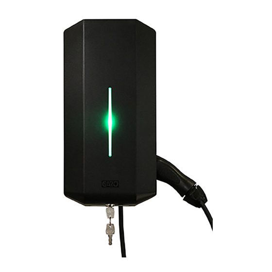
- Page 2 GARO Wallbox GLB GARO Wallbox GLB with cable and connector, type 1 or 2 with type 2 socket outlet (figure 1) Front cover Cover (figure 3) Back panel Indication light Connector type 1 or 2 Type 2 socket outlet RCCB (Residual Current Circuit Breaker) or RCBO (Residual Current Breaker with (figure 2) Overcurrent Protection).
-
Page 3: Table Of Contents
TABLE OF CONTENTS End User instruction About this manual Charging electric vehicles Safety Information Resetting/Conditioning of RCCB or RCBO Technical data Connecting to the wallbox's Wi-Fi access point (AP) Mainboard simplified connection diagram Web interface Dimensional drawing Scheduled charging Limit charging current Assembly instructions for installer Connect charger to a local network via Wi-Fi Box Contents... -
Page 4: About This Manual
Garo Wallbox, models GLB. This document contains general descriptions which are verified to be accurate at the time of printing. However, because continuous improvement is a goal at GARO, we reserve the right to make product modifications at any time. -
Page 5: Safety Information
Safety Information Safety Information Safety Information Hazard categories and special symbols The GLB Wallbox must be grounded through a permanent wiring system. Read these instructions carefully before trying to install, operate, or maintain it. Save the manual for future use. Do not install or use the GLB Wallbox near flammable, explosive, harsh, or combustible materials, chemicals, or vapors. - Page 6 Safety Information Cautions Do not use private power generators as a power source for charging. The front cover must always be locked in its upper position in order to ensure compliance with IP Code IP44. Incorrect installation and testing of the GLB Wallbox could potentially damage To even out the load, it is important to rotate the phases when connecting several either the vehicle’s Battery and/or the GLB Wallbox itself.
-
Page 7: Technical Data
Technical data Technical data Specifications Product type: all GLB models Standards/directives: IEC 61851-1 and IEC TS 61439-7 Installation: on wall Voltage rating: 230V/400 50Hz Installation systems: TT, TN and IT systems Charging type: Mode 3 IP classification: IP44 Mechanical impact IK08 resistance: Application temperature:... -
Page 8: Mainboard Simplified Connection Diagram
Compatible energy meters Config meter to modbus address no.2 (9600 baud, no parity, one stop bit) Config SW1 (1-3) for max current A (fuse rating) • GARO 1-phase energymeter, GNM1D -RS485 • GARO 3-phase energymeter, GNM3D -RS485 Compatible energy meters... -
Page 9: Assembly Instructions For Installer
The product complies with IP Code IP44, with a closed front. It is to be fitted to a wall or GARO Wallbox stand, and all installation must be carried out by an authorised installer and comply with local installation regulations. -
Page 10: Box Contents
Assembly instructions for installer / Box Contents Assembly instructions for installer / Tools and material required Box Contents Tools and Materials Required Before installing the Garo Wallbox, gather the folllowing tools and materials: • Pencil or marker • Hole punch (optional, to push through cardboard template) •... -
Page 11: Step-By-Step Installation
Assembly instructions for installer / Step-by-Step installation Assembly instructions for installer / Step-by-Step installation Step-by-Step Installation (figure 7) Read Safety Instructions All installation must be carried out by an authorised installer and comply with local installation regulations. Ensure the supply cable is powerless. Turn off input power at the circuit breaker before installing, configuring (figure 8) or cleaning of the GLB Wallbox. - Page 12 Assembly instructions for installer / Step-by-Step installation Assembly instructions for installer / Step-by-Step installation Serial no./SSID Connection of phases for 3-phase password Screw the back panel onto the wall using three screws suitable for the wall charger to 3-phase system as below. (Wi-Fi version only) When connecting a 3-phase charger to surface.
- Page 13 Assembly instructions for installer / Step-by-Step installation Assembly instructions for installer / Step-by-Step installation 7 x T20 label explaining charger status indication language label is placed on the side english information label (figure 11) (figure 10) Carefully place the cover in position from the front. Ensure the inserts on the right hand side fit into the groove and the cover is perfectly positioned all around.
-
Page 14: Reducing The Charging Current
Assembly instructions for installer / Step-by-Step installation Assembly instructions for installer / Reducing the charging current Reducing the charging current Turn off input power at the circuit breaker before installing, configuring or cleaning of the GLB Wallbox. All installation must be carried out by an authorised installer and comply with local installation regulations. -
Page 15: Remote Control Of Charger Via Enable Input
Assembly instructions for installer / Remote control of charger via enable input Assembly instructions for installer / Remote control of charger via enable input Remote control of charger via enable input FUSE 2AT Fuse/RCCB FB Turn off input power at the circuit breaker before installing, configuring or Contactor FB cleaning of the GLB Wallbox. -
Page 16: Dynamic Load Management (Dlm) For Individual Chargers
DLM reduces chargning current when demand of current elsewhere increases. Setting the amperage for main fuses To activate DLM, a GARO Modbus energy meter must be installed in the supply distribution box. The following energy meters are approved: Turn off input power at the circuit breaker before installing, configuring or •... - Page 17 Assembly instructions for installer / Setting the amperage for main fuses The energy meter is connected to the terminal “E-meter” on the main board. If the wallbox has an internal energy meter installed, the Modbus connection of the external meter is to be connected in parallel with the internal one.
-
Page 18: Dynamic Load Management (Dlm) For Multiple Chargers In Group
Refer to local standards and regulations not to exceed charging current limitations set to ‘ON’ mode. To activate DLM in a group, a GARO Modbus energy meter must be installed in the supply distribution box. The following energy meters are approved: Termination resistor ‘Datalink’... - Page 19 Assembly instructions for installer / Dynamic Load Management (DLM) for multiple Assembly instructions for installer / Dynamic Load Management (DLM) settings in the chargers in group web interface Example of installation – Data Link, direct connection between wallboxes • Config SW1 (DIP 5-6) (see figure 17-19) •...
- Page 20 Assembly instructions for installer / Dynamic Load Management (DLM) settings in the Assembly instructions for installer / Dynamic Load Management (DLM) settings in the web interface web interface (figure 20) (figure 21) Select current or power limitation Set maximum current (A) or power (kW) In the case of a single-phase charger, if the charger is to be controlled by load balancing, the phase assignation must be set.
-
Page 21: Activating Rfid Reader
GLB Wi-Fi Master / Activating/Deactivating RFID GLB Wi-Fi Master / Activating/Deactivating RFID Activating RFID reader To activate the RFID reader, check the box labelled ‘Request RFID when connecting’ and click ‘Save’. Note the checkbox is only visible when a RFID reader is installed. Activate RFID reader on individual GLB Wallbox To activate RFID reader on a GLB Wallbox that is stand alone (not connected with other GLB Wallboxes), it is important to make the charger a master wallbox. -
Page 22: End User Instruction
The product complies with IP Code IP44, with a closed front. It is to be fitted to a wall or GARO Wallbox stand, and all installation must be carried out by an authorised installer and comply with local installation regulations. -
Page 23: Charging Electric Vehicles
End user instrucion End user instrucion / Charging electric vehicles Charging electric vehicles This equipment should not be used by anyone (including children) with reduced physical, sensory or mental capacity, or anyone lacking in experience or Connect the wallbox to the vehicle using the cable. knowledge, unless they are provided with supervision or prior instruction in how When charging starts, shifting blue light intensity indicates charging in progress. -
Page 24: Resetting/Conditioning Of Rccb Or Rcbo
End user instrucion / Resetting/Conditioning of RCCB or RCBO End user instrucion / Resetting/Conditioning of RCCB or RCBO Resetting/Conditioning of RCCB or RCBO Do not modify the equipment installation or any part of the product. Do not touch the GLB Wallbox’s end terminals with fingers or any other objects. Do not insert foreign objects into any part of the GLB Wallbox. -
Page 25: Connecting To The Wallbox's Wi-Fi Access Point (Ap)
Launch the browser on your device. The device will display the wallbox’s website automatically or go to address: chargebox.garo.se To connect the charger to a wireless network, see the section entitled Connect charger to a local network via Wi-Fi. -
Page 26: Web Interface
GLB Wi-Fi Master / Connecting to the wallbox's Wi-Fi access point GLB Wi-Fi Master / Web interface Web interface To gain access to the wallbox's web interface it must be connected to the same network as a mobile phone, tablet or computer. See the section entitled Connecting to the wallbox's Wi-Fi access point (AP). -
Page 27: Scheduled Charging
GLB Wi-Fi Master / Web interface GLB Wi-Fi Master / Scheduled charging Scheduled charging This feature enables the user to schedule the days and times when the wallbox is accessible. Select scheduled control. Select the day and start/stop time. Click ‘Book’. Check that the correct time has been booked in the schedule. - Page 28 GLB Wi-Fi Master / Scheduled charging GLB Wi-Fi Master / Scheduled charging (figure 31) (figure 30) Choice of scheduled control. Chart showing energy consumption over time. Schedule day and time. Choice of year and month for chart to display. Book. Total energy consumption for the month.
-
Page 29: Limit Charging Current
GLB Wi-Fi Master / Scheduled charging GLB Wi-Fi Master / Limit charging current Limit charging current The charging current can be temporarily reduced during a specific period via the web interface. Limitation of charging current carried out on the printed circuit board through SW2(DIP 1–4) is still active and superordinate. -
Page 30: Connect Charger To A Local Network Via Wi-Fi
The wallbox will attempt to connect to the specified Wi-Fi network. If the data entered is Launch the browser on your device and go to url: chargebox.garo.se incorrect or the connection is unsuccessful for any other reason, the device will return to access point mode after around 10 minutes. -
Page 31: Activating Rfid Tags
GLB Wi-Fi Master / Activating/Deactivating RFID GLB Wi-Fi Master / Activating/Deleting RFID tags Activating RFID tags When RFID is activated, you can choose to ‘Add a new tag’. You can now manually register the tag number in the ‘RFID Number’ field, and then click ‘Save’. Alternatively, you can read the tag number by selecting ‘Read tag from wallbox’. -
Page 32: Care
GLB Wi-Fi Master / Activating/Deleting RFID tags End user instruction / Care Care Do not install or use the GLB Wallbox near flammable, explosive, harsh, or combustible materials, chemicals, or vapors. Turn off input power at the circuit breaker before installing, configuring or cleaning of the GLB Wallbox. -
Page 33: Troubleshooting
End user instruction / Troubleshooting Troubleshooting Indication Type of fault Measure Constant red light The residual-current or Reset. Refer to section on personal protective current Resetting the residual-current breaker or personal protective current has been tripped. breaker. Rapid flashing red light Charging process terminated. -
Page 34: Index
Index INDEX Symbols Dimensional drawing 15 Language labels 18 Standards/directives 13 Drill template 18 Limit charging current 57 Step-by-Step Installation 20 Dynamic Load Management (DLM) 30 Storage temperature 13 Activating RFID reader 40 Mechanical impact resistance 13 Activating RFID tags 61 Enable input 28 Modbus connection 32 Technical data 13... - Page 35 GARO AB Box 203, SE–335 25 Gnosjö Phone: +46 (0) 370 33 28 00 Fax: +46 (0) 370 33 28 50 info@garo.se garo.se...
Need help?
Do you have a question about the Wallbox GLB and is the answer not in the manual?
Questions and answers