Table of Contents
Advertisement
Quick Links
Advertisement
Table of Contents

Related Manuals for Tebas INVERTER S


Summary of Contents for Tebas INVERTER S
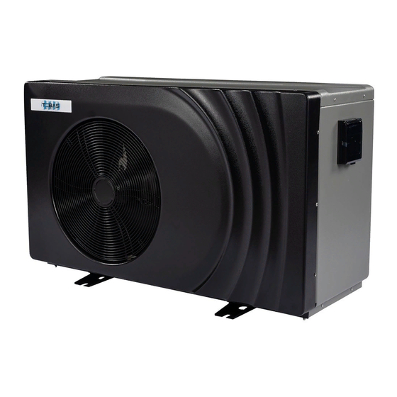
- Page 1 Pool heat pump User manual Inverter pump...
-
Page 2: Table Of Contents
Table of Contents Warning....................3 Symbols used ......................... 3 Authorized persons ................3 Product delivery and general conditions of use .............. 3 Storage, transport and packaging..................4 Standards ........................4 Assembly ....................5 Assembly conditions......................5 Hydraulic connections...................... 6 Electrical connections.. -
Page 3: Warning
Before performing maintenance, service or repair, disconnect the product from the power supply. The indicated activities may only be performed by qualified persons. Tebas is not responsible for damages caused by failure to comply with the provided guidelines or errors in handling, assembly or use. -
Page 4: Storage, Transport And Packaging
(for which please ask your supplier). Tebas is not responsible for the correct operation of products, the selection of which has not been approved by Tebas, and which operate outside the ranges indicated above. -
Page 5: Assembly
Before installing the heat pump, check that the pool supply impedance does not exceed 0.042 Ω. Consult your electricity supplier if necessary. If the energy supplier is unable to change the impedance level, this may translate to a voltage drop of several seconds when starting the pump. -
Page 6: Hydraulic Connections
10 mm² TEBAS 3G 230 V 16 A 25 m 35 m 45 m 80 m INVERTER S TEBAS 3G 230 V 20 A 30 m 40 m 70 m INVERTER M * Maksymalna długość kabla od pompy ciepła do zabezpieczenia prądowego. -
Page 7: Priority Of The Heating Process
: Uziemienie • Connect the relay coil (A1 and A2) to the P1 and P2 terminals of the heat pump. • Connect the relay to the input and output of a normally open contactor, in parallel to the filter pump clock relay. Wiring diagram: Filter pump timer Relay (dry contact) -
Page 8: Use
Water connection Water outlet to the pool Valve Valve Valve To the heat pump Water inlet from the filter Diagram of the bypass system After connecting the heat pump to the swimming pool water system by means of an appropriate bypass, and after making the electrical connections by qualified personnel, check the following: •... -
Page 9: Regulation (Digital Controller)
Regulation (digital controller) Normal screen in heating mode All icons are available Buttons below the display On / Off When the regulator is turned off, the display will show "Stand-by". The button is used to turn the heat pump on / off. After the machine is turned off with this button, it may take a few minutes for the machine to stop completely. - Page 10 Time setting for 3 seconds (the hour will start blinking) Press the button Set the hour by pressing the button Press the button once (the minutes will start flashing) Set the minutes with the button Press the button once to approve.
- Page 11 Water flow detection The heat pump always runs when water flows through it. All models are equipped with a water flow switch that detects whether the water pump is running or not. "Flow" LED is on = water pump is running. Flow LED off = water pump is off.
-
Page 12: Setting The Water Flow
Setting the water flow To optimize the efficiency of the heating process, it is recommended to regulate the water flow with the pool heat pump. Adjustment should be made in accordance with the indications on the pressure gauge. Settings are changed by opening or closing the valve on the main pipe to the pool. -
Page 13: Water Quality
Water quality The water quality must be within the range: Chlorine concentration: less than 1.5 ppm = mg / l; PH level: 7 to 8 In the event of heavy shock treatment, the equipment must be shut off with the bypass valves. After finishing the treatment, return the bypass valves to their original position. -
Page 14: Technical Customer Service
Technical customer service In the event of technical problems, please take the following steps: Provide the technical service with the following basic information: PHOTO of the assembly site Diameter of electric cables and their length Device serial number The value shown by the pressure gauge when the device is turned off The value shown by the pressure gauge when the device is running ON / OFF button setting and whether the button is illuminated Value and pictograms displayed on the digital controller...
Need help?
Do you have a question about the INVERTER S and is the answer not in the manual?
Questions and answers