Table of Contents
Advertisement
Advertisement
Table of Contents

Related Manuals for Tebas BP-100HS-A


Summary of Contents for Tebas BP-100HS-A
- Page 1 Directions for installation and maintenance...
-
Page 2: Table Of Contents
2. Caution …………………………………………………….………………….….. p3 3. Delivery control …………………………………………......p4 4. Technical description ……………………….………………………….. p4 Technical characteristics Outside Inside BP-100HS-A explored view Wire control operation General diagram of the refrigerating circuit Safety and control systems Electric diagram ……………………….…………………………………..p14 5. Installation... -
Page 3: Introduction
Introduction We thank you for having chosen our Heat pump. This installation and maintenance notice contains the necessary information to its installation (delivery control, the installation, the connections) and to its repair. It is a complementary document to the user’s manual which describes its instructions for use. We invite you to read it first. -
Page 4: Technical Description
48 hours and by registered letter with acknowledged receipt. Before any manipulation, check the complete state of the machine. 4 - Technical description Characteristics: MODEL BP-100HS-A Power supply 230V~, 50Hz Heating consumption power * (kW) 2.05 Heating restored power *(kW) 10.5... -
Page 5: Outside
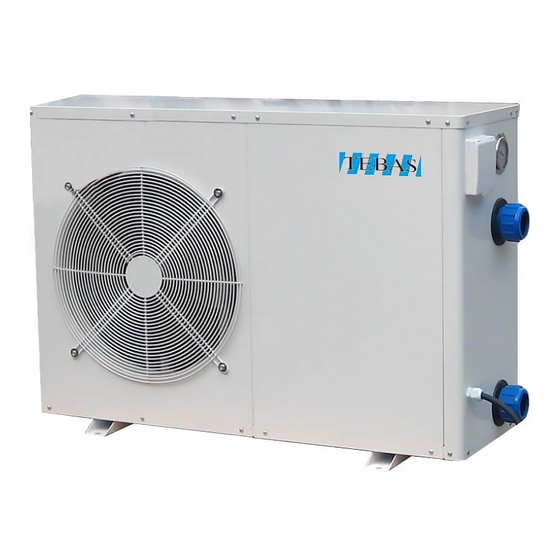
Outside: Fan protection grid Front panel Top cover Control panel Refrigerant pressure manometer Fast connection for water outlet Fast connection for water intlet Wire connection for power supply Inside: (Front sheet cover and panel removed) Evaporator Compressor High and low pressure interruptor Titanium heat exchanger Temperature sensor of swimming pool water Four way valve... -
Page 7: Wire Control Operation
Wire control operation The function of the LED display and control: Set the operation parameter: When the unit powered up but not running, press " " or " " to enter operation parameter interface. (parameter from 0-F, see Operation Parameter Table). ◎... - Page 8 Choose the operation mode: ◎ Press “ ” to power on unit. Under running, the LED displays the water temperature and current mode. ◎ Press “ MODE ” to choose mode(mode can be changed under running) ◎ Press " " or " "...
-
Page 9: Setting The Time
Check current temperature: ◎ Under running, press " " or " " to check the current status of the unit. You can check water/ambient/compressor/copper temperature. Setting the time press “CLOCK” botton to set the time. The time displayed blinks, press “CLOCK” botton again and then use the arrow "... -
Page 10: General Diagram Of The Refrigerating Circuit
General diagram of the refrigerating circuit The heat pump is reversible allowing the swimming-pool’s heating or cooling: Swimming-pool water’s heating mode: The cold and liquid refrigerant fluid absorbs the heat contained in the air through the evaporator (gilled radiator), in which it is vaporizing; it is then put up in pressure and in temperature by the compressor which sends it in the condenser (exchanger) where it loses its heat (in giving it to the water of swimming pool) and comes back in liquid state;... - Page 11 Swimming-pool water’s cooling mode: The 4 way valve reverses the circulation of the refrigerant fluid; the fluid vaporizes in the exchanger (evaporator) in getting the heat of the water, goes through in the compressor which reheats it and through in the gilled radiator (which becomes condenser) where it comes back to liquid state.
-
Page 12: Safety And Control Systems
Safety and control systems The heat pump is fitted out: Temperature control: A temperature sensor of the evaporator, starting the defrosting operation. An ambient temperature sensor ensuring the cut of the heat pump when the temperature of the external air goes down under -7°C (factory settings). -
Page 13: Electric Diagram
Electric diagram... -
Page 14: Installation
5- Installation Rules of installation: Electric and hydraulic connections must be carried out according to standards in effect (NF C 15 100, CE I 364). The machine must be installed outside. The machine must be posed on its ant vibratory studs, set and lying flat and on a massive base (concrete slab);... -
Page 15: Hydraulic Connections
Hydraulic connections: respect imperatively Connection is carried out with a by-pass located on the circuit of filtration, upstream appliances of the Technical room chemical treatment of water. Heat Pump Connect intake/outlet water PVC pipes DN50 to the openings of the machine in following the inlet / outlet Blowing indications (grease the worms before screwing) By-pass... -
Page 16: Electric Connections
Electric connections: CAUTION: before connecting the machine, make sure that the feeder is disconnected to the electrical network. The electric installation must be carried out by an experienced electrician and the supply must come from a severing equipment and differential protection; the whole must be carried out according to standards' in force in the country where the material is installed. -
Page 17: Procedure Of Use
Procedure of use External Appliance Heat pump Action Display or Button of heat answer pump Engage the circuit breaker of the heat pump Put the heat pump Display current water under tension temperature Engage the circuit breaker of pump of filtration Put in circulation the swimming... -
Page 18: Water Flow And Refrigerating Circuit Pressure
6- Water Flow and refrigerating circuit pressure After putting into service, do the settings of pressure of the refrigerant circuit for having an optimal operating of the heat pump, following: Stage 1: Before starting the Heat Pump, ambient temperature around 20°C, refrigerant meter shows pressure from 14 to 16kg/cm². -
Page 19: Defrosting
7- Defrosting The defrosting is necessary only in heating mode. Sequences of the defrosting: 1- Start The defrosting is engaged if the following conditions are at the same time fulfilled: - the defrosting sensor temperature goes down to 15°C - the compressor runs without stopping for 40 minutes - the defrosting sensor temperature goes down to -7°C 2- The compressor and the fan stop 3- After 25 seconds, the 4 way valve shifts... - Page 20 9 – Error codes and what to do: This table explains the error codes caused by a defective regulating component or by a security operation. Second reason if Screen and state Component Possible Intervention of the heat pump intervention is without effect PP 01 Sensor disconnected,...
Need help?
Do you have a question about the BP-100HS-A and is the answer not in the manual?
Questions and answers