
Related Manuals for RKI Instruments 82-5220


Summary of Contents for RKI Instruments 82-5220
- Page 1 82-5220 24 VDC Solenoid ESTOP Operator’s Manual Part Number: 71-0569 Revision: P1 Released: 8/13/21 www.rkiinstruments.com...
- Page 2 Product Warranty RKI Instruments, Inc. warrants gas alarm equipment sold by us to be free from defects in materials, workmanship, and performance for a period of one year from the date of shipment from RKI Instruments, Inc. Any parts found defective within that period will be repaired or replaced, at our option, free of charge.
-
Page 3: Table Of Contents
About the 82-5220 ........ -
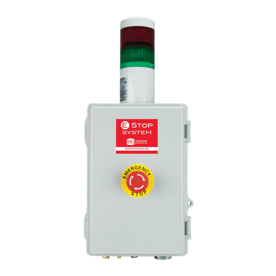
Page 4: Overview
The 82-5220 is a fixed-mounted device with a relay, stack light, and emergency stop button. It requires 24 VDC to operate. A relay inside the 82-5220 is field-wired into the power line of a user-supplied solenoid valve. When the emergency stop button on the front of the housing door is pushed, power to the connected solenoid valve is cut off. -
Page 5: Description
Figure 1: External Component Location Housing The 82-5220’s PBT/PC blend housing is weather- and corrosion-resistant. It is suitable for installation where general purpose equipment is in use. The housing door is hinged on the left side and is secured by two latches on the right side. A panel inside the housing allows for component installation and mounting. -
Page 6: Internal Description
Terminal Strip Figure 2: Internal Component Location Relay A DPDT relay installed on the right side of the 82-5220 controls the stack light’s LED color and also controls the power to the solenoid valve. Emergeny Stop Button Connections The emergency stop button’s wiring connections are visible on the back of the door. They are factory wired to the Field Wiring Terminal Strip. -
Page 7: Installation
The relay and emergency stop button connections are wired to a terminal strip located in the lower right corner of the 82-5220. The terminal strip makes wiring to 24 VDC, the solenoid valve, and a remote relay contact (optional) more accessible. - Page 8 4. Insert 3/16 in. screws through the mounting slots to secure the housing to the mounting surface. 7.19 Ø .23 x .3 slot, 4X 18.77 11.41 6.04 3/4 NPT Conduit Hub 8.09 Figure 3: Outline & Mounting Dimensions 8 • 82-5220...
-
Page 9: Factory Wiring
Y el lo w Re d Re d Re d S OL EN OID T O ALARM INP UT CO NT ROL CO NT AC TS P OW E R 24 V DC Figure 4: Factory Wiring 82-5220 • 9... -
Page 10: Field Wiring
5220 to a remote relay contact provides another way to cut the power line to the solenoid valve. If you do connect the 82-5220 to a remote relay contact, the relay contact set used must be normally open and the relay must be configured as normally energized. - Page 11 (as shown in Figure 5 and Figure 6 below). When the relay contact is closed, power is supplied to the solenoid valve. When the relay contact opens, the power line to the solenoid valve is cut. NOTE: The relay that you connect to the 82-5220 must be configured as normally energized. Field Wiring Terminal...
-
Page 12: Start Up
1. Be sure the emergency stop button is not pushed. If it is pushed, turn it clockwise to reset it. 2. Turn on power to the 82-5220, power to the solenoid valve, and power to the device whose relay contact is wired to the 82-5220 (if used). -
Page 13: Operation
Replacing the Fuse 1. Turn off or disconnect power to the 82-5220. 2. Open the 82-5220 housing door. 3. Locate the fuse. It is in the power line shown below and is secured to the right side of the housing with a zip tie. -
Page 14: Parts List
9. Use a new zip tie to connect the fuse holder to the right side of the housing. 10. Close the housing door. 11. Plug in or connect power to the 82-5220. Parts List Table 2 lists replacement parts and accessories for the 82-5220. Table 2: Parts List Part Number Description...
Need help?
Do you have a question about the 82-5220 and is the answer not in the manual?
Questions and answers