RKI Instruments GX-2012 Operator's Manual
Confined space multi gas detector
Hide thumbs
Also See for GX-2012:
- Operator's manual (163 pages) ,
- Quick reference manual (48 pages) ,
- Instructions (2 pages)

Subscribe to Our Youtube Channel
Related Manuals for RKI Instruments GX-2012


Summary of Contents for RKI Instruments GX-2012
- Page 1 GX-2012 Operator’s Manual Part Number: 71-0335 Revision: C Released: 7/23/15 www.rkiinstruments.com...
- Page 2 Typical calibration frequencies for most applications are between 1 and 3 months, but can be required more often or less often based on your usage. GX-2012 Operator’s Manual...
- Page 3 Warranty RKI Instruments, Inc. warrants the GX-2012 sold by us to be free from defects in materials, workmanship, and performance for a period of two years from the date of shipment from RKI Instruments, Inc. This includes the instrument and the original sensors. Replacement parts are warranted for 1 year from the date of their shipment from RKI Instruments, Inc.
-
Page 4: Table Of Contents
About the GX-2012 ........ - Page 5 Performing a Fresh Air Adjustment, Normal Mode... . . 27 Turning Off the GX-2012, Normal Mode ..... 28 Measuring Mode, Normal Operation .
- Page 6 Preparing for Calibration or Bump Test ..... . 58 Calibrating the GX-2012........58 Bump Testing the GX-2012.
- Page 7 Replacing the Lithium Ion Battery Pack ..... 147 Recharging the Lithium Ion Battery Pack in the Instrument ..148 Table of Contents GX-2012 Operator’s Manual...
- Page 8 Calibrating the GX-2012 ........
-
Page 9: Chapter 1: Introduction
Chapter 1: Introduction Overview This chapter briefly describes the GX-2012. This chapter also describes the GX-2012 Operator’s Manual (this document). Table 1 at the end of this chapter lists the specifications for the GX-2012. About the GX-2012 Using an advanced detection system consisting of up to five gas sensors, the... - Page 10 • ATEX certification for II1G Ex ia IIC T4 Ga WARNING: The GX-2012 detects oxygen deficiency, elevated levels of oxygen, combustible gases, carbon monoxide, and hydrogen sulfide, all of which can be dangerous or life threatening. When using the GX-2012, you must follow the instructions...
-
Page 11: Specifications
Specifications Table 1: GX-2012 Specifications Target Gas %LEL % Volume Oxygen (O Hydrogen Carbon Combustible Combustible Sulfide Monoxide (CO) (Methane (Methane Calibration Calibration Standard)* Standard) Range 0-100% LEL 0 - 100% vol 0-40.0% vol 0-100 ppm 0-500 ppm (Increment) (1% LEL) (1% vol) (0.1 vol%) -
Page 12: About This Manual
Approximately 171(H) x 65(W) x 39(D) mm (5.6”H x 2.5”W x 1.5”D) and Weight Approximately 310 g (11 oz.) *Some versions of the GX-2012 are available with the LEL sensor factory set for HC (general hydrocarbons) and calibrated to isobutane. Consult RKI Instruments, Inc. for further information. -
Page 13: Chapter 2: Description
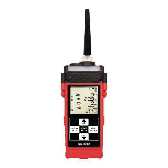
Chamber Opening Alarm Battery Arrays Cover (alkaline version) DISPLAY POWER RESE T (ADJ) ENTER SILENCE Charging Control (SHIFT) Buttons Contacts IR Port (behind button label) Figure 1: Components of the GX-2012, Front & Back GX-2012 Operator’s Manual Overview • 5... -
Page 14: Case
The alkaline battery version also includes a battery cover release knob. The battery pack and flow chamber are located on the back of the GX-2012. The inlet filter holder is located on the top of the GX-2012 case. - Page 15 The oxygen reacts in the cell and produces a voltage proportional to the concentration of oxygen. The voltage is measured by the GX-2012’s circuitry, converted to a measurement of gas concentration, and displayed on the LCD.
-
Page 16: Lcd
A digital LCD (liquid crystal display) is visible through a clear plastic window on the front of the case. The LCD display simultaneously shows the gas reading for all installed sensors. The display also shows information for each of the GX-2012’s program modes. 8 • Instrument Description GX-2012 Operator’s Manual... -
Page 17: Control Buttons
IrDA protocol. A computer’s infrared port or an IrDA/USB cable connected to a computer’s USB port can be used to download data saved by the GX-2012 to a computer using the GX- 2012 Data Logger Management Program. See the GX-2012 Data Logger Management Program operator’s manual for data logging and downloading... -
Page 18: Buzzer
Push the battery pack latch on the bottom of the unit toward the front of the unit to release the pack. The lithium ion battery pack can be recharged by placing the GX-2012 in its optional battery charging station or by placing the battery pack in the charging station. -
Page 19: Pump
GX-2012 because of flow rate reduction. Flow Chamber The flow chamber is on the back of the GX-2012 and is held in place by three phillips screws. The flow chamber seals to the rubber sensor gasket which seals to the sensor faces inside the GX-2012 and routes flow from the pump to the sensors and to the exhaust port (also a part of the flow chamber). -
Page 20: Standard Accessories
The belt clip allows the GX-2012 to be securely attached to a belt. Wrist Strap A wrist strap is included with the GX-2012 and can be attached to the right or left wrist strap installation feature. Sample Hose & 10 Inch Probe A 10 foot sample hose and a 10 inch probe are included as standard with the GX-2012. -
Page 21: Optional Accessories
56. Rechargeable Lithium Ion Battery Pack A rechargeable lithium ion battery pack is available for the GX-2012. A fully charged battery pack will power the GX-2012 for 10 hours. The batteries will last for a minimum of 500 charge cycles. See the “Parts List” on page 158 for ordering information. - Page 22 VAC if an appropriate plug adapter is provided. The AC charging station is shown below in Figure 5. AC Adapter Charging Adapter Jack Adapter Jack Contacts To AC Outlet Charge LED Rear View Top View Figure 5: GX-2012 AC Powered Charging Station 14 • Optional Accessories GX-2012 Operator’s Manual...
- Page 23 An optional DC powered charging station is available with a vehicle plug 12 VDC adapter. It uses the same charging base as the AC charging station but comes with a velcro strap to secure the GX-2012 in the charging base. Adapter Jack...
-
Page 24: Optional Probes
End Plugged Figure 9: Barhole Probe An optional bar hole probe is available for the GX-2012. It is designed to be used when the GX-2012 is operated in Bar Hole Mode to check bar holes when tracking down underground gas pipe leaks (see “Chapter 4: Using the GX-2012 in Bar Hole Mode”... - Page 25 As you lower the probe down, if it hits water, it will float and continue to monitor the area. See the “Parts List” on page 158 for probe ordering information. GX-2012 Operator’s Manual Optional Accessories • 17...
-
Page 26: Purge Tee Fitting
Figure 12: Purge Tee Fitting External Dilution Fitting An external dilution fitting is available for the GX-2012. It is a 1:1 dilution fitting and is designed to mate with the inlet fitting and accept a sample hose or probe. The fittings are made with brass and nickel plated brass and are appropriate for use with the four standard gases. -
Page 27: Chapter 3: Using The Gx-2012 In Normal Mode
While in Normal Mode, Display Mode and Calibration Mode are accessible. If a standard version of the GX-2012 is ordered, it is shipped with Bar Hole Mode disabled so that the instrument only runs in Normal Mode when turned... - Page 28 Press and release the POWER ENTER button to continue accumulating time-weighted average (TWA), PEAK readings, and time in operation from the last time the GX-2012 was used. The short-term exposure limit [STEL] reading is reset each time the GX- 2012 is turned on.
- Page 29 FAIL C--LIMIT The GX-2012 cannot be used until a calibration has been performed either by selecting AUTO CAL or ONE CAL in the Maintenance Mode menu. See “Calibrating Using Auto Calibration” on page 105 or “Calibrating Using Single Calibration” on page 108 for calibration instructions.
- Page 30 FAIL B--LIMIT The GX-2012 cannot be used until a bump test has been performed by selecting BUMP in the Maintenance Mode menu. See “Performing a Bump Test” on page 111 for bump testing instructions. •...
- Page 31 S Id - - - - - - - - 8. The Date/Time Screen appears for a few seconds. 2011 22:39 DATE This screen displays the current year, month, day, and time. GX-2012 Operator’s Manual Start Up, Normal Mode • 23...
- Page 32 If the combustible channel is set up as %volume only using the HC Range Screen in Display Mode, it will automatically revert to Autoranging when it is turned off and on again and the no alarm acknowledgement screen will not appear. 24 • Start Up, Normal Mode GX-2012 Operator’s Manual...
-
Page 33: Turning On The Gx-2012 In Normal With All Modes Active
Normal Mode during the start up sequence to operate in Normal Mode. The standard factory setting for L./B. MODE is OFF. See “Chapter 4: Using the GX-2012 in Bar Hole Mode” on page 72 for a description of Bar Hole Mode or “Chapter 5: Using the GX-2012 in Leak Check Mode”... - Page 34 Leak Check Mode Select Screen will not appear. 1. Connect the tapered rubber nozzle or the sample hose to the GX-2012’s quick connect inlet fitting. 2. If a sample hose is used, screw the probe onto the sample hose’s threaded fitting.
-
Page 35: Performing A Fresh Air Adjustment, Normal Mode
Screen. Performing a Fresh Air Adjustment, Normal Mode Before using the GX-2012, it is recommended to set the fresh air readings for the target gases by performing a fresh air adjustment. This will set the combustible gas, CO, and H S channels to zero and the OXY channel to 20.9%. -
Page 36: Turning Off The Gx-2012, Normal Mode
See “Updating the LCD Back Light Time Setting” on page 135 to program backlight duration. If the BEEP. SET menu item in Maintenance Mode is turned on, the GX-2012 beeps once every 5 minutes to confirm that it’s operating. See “Updating the Confirmation Beep Setting” on page 129 for instructions to update the setting. -
Page 37: Using Optional Probes And Fittings
This probe is designed to be used in a tank or a well that may have water or some other liquid at the bottom. To use the 8 meter hose with floating probe: 1. Start up the GX-2012 as described in “Start Up, Normal Mode” on page 19. - Page 38 19. 2. Connect the purge tee fitting to the GX-2012’s quick connect inlet fitting. 3. Insert the sample port into the flowing gas. The vent port will allow any excess gas to release to the atmosphere to avoid damage to pump or sensors.
-
Page 39: Combustible Gas Detection
NOTE: The GX-2012 can be calibrated either with or without the dilution fitting in place. If calibrated without the dilution fitting in place, then display readings must be doubled to determine the actual gas concentration. If calibrated with the dilution fitting in place, then a sample bag must be used during calibration, and the display readings will be the actual gas concentrations. - Page 40 Applications with High Levels of Combustible Gas The GX-2012 provides the % LEL sensor with some protection by turning off the % LEL sensor power temporarily when it determines that a % LEL over scale (more than 100% LEL) concentration of combustible gas is present.
-
Page 41: Snap Log Mode
To enter Snap Log Mode and record snap log data: 1. Press and hold the (SHIFT) button, then press and hold the AIR button and hold both until you hear a beep. The unit will cycle through the following screens. GX-2012 Operator’s Manual Measuring Mode, Normal Operation • 33... - Page 42 This ID number increases sequentially with each set of snap log data taken. The second screen displays what Station ID will be associated with this snap log. The third screen displays the year, month, 34 • Measuring Mode, Normal Operation GX-2012 Operator’s Manual...
- Page 43 The unit will immediately return to the Normal Operation Screen. 5. The data recorded in Snap Log Mode can be viewed in Display Mode. See “Snap Logging Screen” on page 53 for more information. GX-2012 Operator’s Manual Measuring Mode, Normal Operation • 35...
-
Page 44: Measuring Mode, Alarms
Measuring Mode, Alarms This section covers alarm indications in Measuring Mode. It also tells you how to reset the GX-2012 after an alarm has occurred and how to respond to an alarm condition. NOTE: False alarms may be caused by radio frequency (RF) or electromagnetic (EMI) interference. - Page 45 • Gas readings Buzzer sounds a double replaced by FAIL pulsing tone (two pulses in quick succession) • Fan symbol disappears • BATTERY displayed along bottom of screen • Alarm LED arrays flash GX-2012 Operator’s Manual Measuring Mode, Alarms • 37...
-
Page 46: Resetting And Silencing Alarms
This alarm can also occur in Bar Hole Mode Resetting and Silencing Alarms You can set the GX-2012’s gas alarms as latching or self-resetting alarms (see “Updating the Alarm Latching Setting” on page 117) and the buzzer operation as silenceable or not silenceable (see “Updating the Alarm Silence Setting”... -
Page 47: Responding To Alarms
The gas reading must fall below (or rise above for an oxygen low alarm) the low alarm setting before you can reset the alarm. Press the RESET SILENCE button to reset the alarm. The LEDs and buzzer turn off and the GX-2012 alarm indications on the display turn off. - Page 48 RKI Instruments, Inc. for further instructions. Responding to Battery Alarms WARNING: The GX-2012 is not operational as a gas monitoring device during a dead battery alarm. Take the GX-2012 to a non- hazardous area and replace or recharge the batteries as described in “Replacing or Recharging the Batteries”...
- Page 49 2. Attempt to change the date using the DATE menu time in Maintenance Mode. See “Updating the Date and Time Settings” on page 103. 3. If the date cannot be set correctly, contact RKI Instruments, Inc. as soon as possible.
-
Page 50: Inert Mode
Maintenance Mode. See “Updating the Alarm Point Settings” on page 120 for instructions to set the alarm points. Start Up and Operation 1. With the oxygen alarm pattern set to H-HH, start up the GX-2012 as described in “Turning On the GX-2012, Normal Mode Only” on page 19. -
Page 51: Display Mode
20.9 INERT 3. Since the oxygen concentration in fresh air is above both oxygen alarm points, the GX-2012 will go into alarm if turned on in a fresh air environment. Display Mode This section describes using the GX-2012 in Display Mode. With the GX- 2012 in Display Mode, you can: •... -
Page 52: Hc Range Screen
2012 automatically returns to Measuring Mode. HC Range Screen This screen displays only if your GX-2012 is equipped with both the catalytic % LEL combustible sensor and the TC % volume combustible sensor. It allows you to select the display units for the combustible channel as % LEL/% volume autoranging or % volume. -
Page 53: Stel Screen
See “Turning On the GX-2012, Normal Mode Only” on page 19. To reset the peak readings during operation, press and hold the RESET SILENCE button for a few seconds while in the peak screen. -
Page 54: Alarm Points Screen
Press the POWER ENTER button to proceed to view the full scale settings. Use the AIR or (SHIFT) buttons to scroll through screens showing the different settings. vol% %LEL 40.0 100.0 F. S. %LEL 19.5 WARNING %LEL 23.5 30.0 ALARM 46 • Display Mode GX-2012 Operator’s Manual... -
Page 55: Operation Time Screen
The operation time screen displays the time in minutes since the GX-2012 was last turned on. The operation time may be continued from the last time the GX-2012 was in operation by using the lunch break option. See “Turning On the GX-2012, Normal Mode Only” on page 19. -
Page 56: Date/Time Screen
The table below illustrates how much data logging time is available for the various interval times. It assumes that the unit is set up with all 5 sensors and there are no alarm occurrences. Table 6: Data Logging Capacity, 5 Sensor GX-2012 Interval Data Logging Time... -
Page 57: Clear Data Logger Screens
The clear data logger screens allow you to clear the data logger storage. You can set the GX-2012 to overwrite the oldest data when the data log is full. See “Updating the Datalog Overwrite Setting” on page 129. The bottom line of the screen alternates between LG CLEAR, NO /DISP, and YES/ENT. -
Page 58: Pump Off Screen
Maintenance Mode is turned ON. The factory setting for POFF DSP is OFF. The GX-2012 pump can be turned on and off in this screen. The bottom line of this screen alternates between PUMP OFF, NO /DISP, and YES/ENT. -
Page 59: User Id Screen
The user ID is saved to the data logger for that session when you turn off the GX-2012 or change users during operation. This allows you to change the user ID during operation and have each user ID that was used during an operating session saved for the corresponding data. -
Page 60: Station Id Screen
The station ID is saved to the data logger for that session when you turn off the GX-2012 or change stations during operation. This allows you to change the station ID during operation and have each station ID that was used during an operating session saved for the corresponding data. -
Page 61: Snap Logging Screen
REC. DATA, NO /DISP, and YES/ENT. d ISP REC. DATA 2. Press and release the POWER ENTER button. If no snap logs have been performed, the following screen will appear. NO DATA GX-2012 Operator’s Manual Display Mode • 53... - Page 62 The gas readings and station ID will change but the snap log ID is not visible from this screen. To scroll through the data by viewing the snap log ID number, press and release POWER ENTER. 54 • Display Mode GX-2012 Operator’s Manual...
-
Page 63: Peak Bar Select Screen
The screen indicates the current setting. BAR ON 2. Press and release the POWER ENTER button. PEAK BAR 3. Use the AIR and (SHIFT) buttons to make your selection and press and release the POWER ENTER button. GX-2012 Operator’s Manual Display Mode • 55... -
Page 64: Datalogging
Data Logging NOTE: The GX-2012 logs data in both Normal Mode and Bar Hole Mode. The GX-2012 features the ability to log data to its internal memory and download it to a computer via the infrared communications port located just below the RESET SILENCE button. -
Page 65: Calibration Mode
Typical calibration frequencies range from monthly to quarterly. You can program the GX-2012 to notify you when it is due for calibration. See “Updating the Calibration Reminder Setting” on page 130. Calibration/Bump Test Supplies and Equipment To calibrate or bump test the GX-2012, you will need: •... -
Page 66: Preparing For Calibration Or Bump Test
4. Continue to hold the AIR button until the display prompts you to release it. The GX-2012 will set the fresh air reading for all channels as it counts down from 8. If the combustible channel is set as %LEL only or vol% only, there is no countdown period. - Page 67 Calibration Mode. The first item in the calibration menu, AIR CAL, displays. NOTE: The following screens illustrate a four-gas GX-2012 with both a %LEL and a %volume combustible gas sensor as examples only. Your GX-2012 may display slightly different screens.
- Page 68 If all concentrations match, go to step 12. If one or more concentrations do not match, continue with step 5. 5. To adjust the values on the screens, hold down the (SHIFT) button, 60 • Calibration Mode GX-2012 Operator’s Manual...
- Page 69 4 sensors or the %volume combustible gas sensor. The following instructions illustrate calibrating the standard 4 sensors first, then the %volume combustible gas sensor. GX-2012 Operator’s Manual Calibration Mode • 61...
- Page 70 If any of the sensors cannot calibrate to the proper value, FAIL displays along the bottom of the screen and the GX-2012 lists the sensor(s) that failed to calibrate. In the example below, the OXY and H S channels failed calibration.
- Page 71 CAUTION: The single calibration method does not have a “FAIL” notification. If a sensor cannot be set to agree with the calibration source, see “Troubleshooting” on page 143. GX-2012 Operator’s Manual Calibration Mode • 63...
- Page 72 MAINTENANCE vol% - - - ONE CAL 4. Press and release the POWER ENTER button. The single calibration screen displays for the sensor you selected. The gas reading flashes. MAINTENANCE %LEL ONE CAL 64 • Calibration Mode GX-2012 Operator’s Manual...
- Page 73 12. Press and release the POWER ENTER button to exit ONE CAL. 13. With the ONE CAL menu option displayed, press the (SHIFT) button until the NORMAL menu option is displayed. 14. Press and release the POWER ENTER button to return to Measuring Mode. GX-2012 Operator’s Manual Calibration Mode • 65...
-
Page 74: Bump Testing The Gx-2012
ON. See “Turning the Bump Test Function On or Off” on page 125 for instructions. NOTE: The GX-2012 uses parameters defined in the BUMP--SET menu item of Maintenance Mode while performing a bump test. To view or update these parameters, see “Updating the Bump Test Parameters”... - Page 75 9. Connect the tubing from the demand flow regulator to the rigid tube on the probe then quickly press and release the POWER ENTER button. The unit will begin counting down from 30. GX-2012 Operator’s Manual Calibration Mode • 67...
- Page 76 If one or more sensors fail the bump test, see “Troubleshooting” on page 143 to investigate the cause of the failure and replace the failed sensor or sensors if necessary. • Disconnect the tubing from the probe. 68 • Calibration Mode GX-2012 Operator’s Manual...
- Page 77 APPLY. The calibration time will begin to countdown in seconds in the lower right of the screen. The calibration time counted down during a GX-2012 Operator’s Manual Calibration Mode • 69...
- Page 78 (SHIFT) button to scroll between the calibration/bump test results, the bump test gas readings, and the calibration gas readings. MAINTENANCE %LEL BUMP/CAL MAINTENANCE %LEL 12.0 23.0 BUMP/ MAINTENANCE %LEL 12.0 25.0 /CAL 70 • Calibration Mode GX-2012 Operator’s Manual...
- Page 79 12. Unscrew the demand flow regulator from the calibration cylinder. 13. With the BUMP menu option displayed, press the (SHIFT) button until the NORMAL menu option is displayed. 14. Press and release the POWER ENTER button to return to Measuring Mode. GX-2012 Operator’s Manual Calibration Mode • 71...
-
Page 80: Chapter 4: Using The Gx-2012 In Bar Hole Mode
When the GX-2012 is in Bar Hole Mode, only the combustible and oxygen channels are displayed. If a GX-2012 is intended for bar hole testing, it is shipped with Bar Hole Mode enabled so that the operator must choose which operational mode to use when the unit is turned on. - Page 81 If the unit is due for calibration and CL EXPRD is set to CONFIRM (factory setting), then the following screen displays. C--LIMIT The alarm LED’s and buzzer will pulse several times. After this, press and release the RESET SILENCE button to continue. GX-2012 Operator’s Manual Start Up, Bar Hole Mode • 73...
- Page 82 FAIL C--LIMIT The GX-2012 cannot be used until a calibration has been performed either by selecting AUTO CAL or ONE CAL in the Maintenance Mode menu. See “Calibrating Using Auto Calibration” on page 105 or “Calibrating Using Single Calibration” on page 108 for calibration instructions.
- Page 83 FAIL B--LIMIT The GX-2012 cannot be used until a bump test has been performed by selecting BUMP in the Maintenance Mode menu. See “Performing a Bump Test” on page 111 for bump testing instructions. •...
- Page 84 9. The Date/Time Screen appears for a few seconds. 2011 22:39 DATE This screen displays the current year, month, date, and time. 10. The Battery Level and Alarm Pattern Screen appears next. bAtt AL-H 76 • Start Up, Bar Hole Mode GX-2012 Operator’s Manual...
- Page 85 • TWA alarm setpoint for the CO and H S channels 12. If the GX-2012 experiences a sensor failure during start up, a screen indicating which sensor failed displays. In the example below, the combustible gas %volume sensor has failed.
-
Page 86: Performing A Fresh Air Adjustment, Bar Hole Mode
S sensor is installed and fails, press and release the RESET SILENCE button to acknowledge the failure and continue to Bar Hole Mode. 13. The GX-2012 is now operating in Bar Hole Mode. The pump is off and the following screen appears. BAR HOLE MODE %LEL 20.9... -
Page 87: Bar Hole Testing
Bar Hole Mode also allows you to initiate an air purge cycle to purge gas from the GX-2012 after a sample is taken. - Page 88 BAR HOLE MODE %LEL 3. Take the GX-2012 to the bar hole that will be tested. 4. Insert the probe into the bar hole and press and release the POWER ENTER button. The pump will turn on and the sample period will begin with the sample period counting down in seconds in the lower right corner of the display.
- Page 89 PEAK 7. If a high concentration of methane is encountered, a fresh air purge can be performed to purge the hose, probe and GX-2012 of gas before the next bar hole test. To perform a purge, do the following: •...
-
Page 90: Turning Off The Gx-2012, Bar Hole Mode
10. To exit Bar Hole Mode and return to the Mode Select Screen at any time, press and hold the (SHIFT) button for 5 seconds. Turning Off the GX-2012, Bar Hole Mode 1. Press and hold the POWER ENTER button. 2. The unit will initiate a bar hole measurement. Keep holding the POWER ENTER button. -
Page 91: Chapter 5: Using The Gx-2012 In Leak Check Mode
When the GX-2012 is in Leak Check Mode, only the combustible channel is displayed. If a GX-2012 is intended for leak check testing, it is shipped with Leak Check Mode enabled so that the operator must choose which operational mode to use when the unit is turned on (see “Turning On... - Page 92 2. If a sample hose is used, connect the sample hose to the GX-2012’s quick connect inlet fitting. NOTE: If a probe is used when using the GX-2012 in Leak Check Mode, use the standard probe, not the bar hole probe.
- Page 93 USE, then the following screen displays. FAIL C--LIMIT The GX-2012 cannot be used until a calibration has been performed either by selecting AUTO CAL, or ONE CAL in the Maintenance Mode menu. See “Calibrating Using Auto Calibration” on page 105 or “Calibrating Using Single Calibration”...
- Page 94 USE, then the following screen displays. FAIL B--LIMIT The GX-2012 cannot be used until a bump test has been performed by selecting BUMP in the Maintenance Mode menu. See “Performing a Bump Test” on page 111 for bump testing instructions.
- Page 95 This screen displays the current year, month, date, and time. 10.The Battery Level and Alarm Pattern Screen appears next. bAtt AL-H AL -- H indicates latching (hold) alarms and AL -- A indicates self- GX-2012 Operator’s Manual Start Up, Leak Check Mode • 87...
- Page 96 D: V 11.The display then indicates the full scale values for all channels. 12.If the GX-2012 experiences a sensor failure during start up, a screen indicating which sensor failed displays. In the example below, the catalytic LEL sensor has failed.
-
Page 97: Performing A Fresh Air Adjustment, Leak Check Mode
This will set the combustible gas channel to zero. RKI Instruments recommends allowing the GX-2012 to run for as long as possible after turning on the instrument before performing a fresh air adjustment. -
Page 98: Leak Testing
Setting the Display Range Value The GX-2012 Leak Check Mode has 4 display range ppm values to choose from: 500 ppm, 1000 ppm, 2000 ppm, and 5000 ppm. NOTE: The GX-2012 is always detecting combustible gas up to 5000 ppm. -
Page 99: Locating A Leak
Locating a Leak 1. Start up the GX-2012 as described above in “Turning On the GX- 2012, Leak Check Mode” on page 83. 2. Move the probe tip or tapered nozzle tip back and forth along the area where a leak is suspected. -
Page 100: Turning The Alarm On And Off In Leak Check Mode
LEL range until the readings decrease back to the ppm range. Turning the Alarm On and Off in Leak Check Mode The alarm buzzer can be turned off and on when the GX-2012 is in Leak Check Mode. This setting only applies to Leak Check Mode and does not affect buzzer operation in Normal or Bar Hole Mode. -
Page 101: Peak Hold Mode
To enter Peak Hold Mode: 1. Turn the GX-2012 on as described in “Turning On the GX-2012, Leak Check Mode” on page 83. Select the desired display range. In the example below, 500 ppm has been selected. - Page 102 1. Turn the GX-2012 on as described in “Turning On the GX-2012, Leak Check Mode” on page 83. Select the desired display range. In the example below, 500 ppm has been selected. Press and hold the (SHIFT) button, then press and hold the AIR button and hold both until you hear a beep.
- Page 103 RESET SILENCE button. 6. Repeat steps 2 through 5 to take additional snap log data. 7. To exit Snap Log Mode at any time without taking a snap log or GX-2012 Operator’s Manual Leak Testing • 95...
-
Page 104: Viewing Snap Log Data In Leak Check Mode Operation
Snap log data can be viewed while in Leak Check Mode. If snap log data was taken while in Normal Operation, that data will also appear. 1. Turn the GX-2012 on as described in “Turning On the GX-2012, Leak Check Mode” on page 83. - Page 105 IDs and view what time and day they were taken. Snap log data that was taken in Leak Check Mode operation will have two snap log ID numbers. One number is for the base reading and the other is for the peak reading. GX-2012 Operator’s Manual Leak Testing • 97...
- Page 106 VALVE 3 (SHIFT) LEAK CK MODE LEAK CK MODE 2012 Leak Check POWER Mode Operation ENTER Base Data 14:17 5000 M009 VALVE 3 (SHIFT) 2011 %LEL Normal POWER 22.0 Operation ENTER Data 22:39 M007 98 • Leak Testing GX-2012 Operator’s Manual...
-
Page 107: Turning Off The Gx-2012, Leak Check Mode
6. To exit snap log data viewing and return to Leak Check Mode Operation, press and release the DISPLAY (ADJ) button. Turning Off the GX-2012, Leak Check Mode 1. Press and hold the POWER ENTER button. 2. The buzzer will pulse for about three seconds and TURN OFF will appear at the bottom of the screen. -
Page 108: Chapter 6: Maintenance Mode
Chapter 6: Maintenance Mode Overview This chapter describes the GX-2012 in Maintenance Mode. In Maintenance Mode, you can: • update the date and time • perform a fresh air adjust • perform an auto calibration • perform a single calibration •... -
Page 109: Tips For Using Maintenance Mode
Maintenance Mode. Although it will respond to gas in parts of AUTO CAL and ONE CAL, there are no alarm indications. 1. Take the GX-2012 to a non-hazardous location, and turn it off if it is on. GX-2012 Operator’s Manual Tips for Using Maintenance Mode • 101... - Page 110 PASSWORD menu item in Maintenance Mode. 4. If you enter an incorrect password, an error screen will appear. PASSWORD You must turn the unit off and reenter Maintenance Mode using the correct password. 102 • Using Maintenance Mode GX-2012 Operator’s Manual...
-
Page 111: Updating The Date And Time Settings
The Date menu item displays after you enter the minutes setting. Performing a Fresh Air Adjustment 1. Confirm you are in a fresh air environment that is free of toxic and combustible gases and of normal oxygen concentration, 20.9%. GX-2012 Operator’s Manual Using Maintenance Mode • 103... - Page 112 The unit will count down from 8 as it performs the fresh air adjust. MAINTENANCE RELEASE Once it has finished, it will return to the AIR CAL menu screen. 104 • Using Maintenance Mode GX-2012 Operator’s Manual...
-
Page 113: Calibrating Using Auto Calibration
2. Install the demand flow regulator onto the calibration cylinder. 3. Connect the sample tubing to the demand flow regulator. 4. Install the hose and probe to the GX-2012. 5. You may only calibrate either the standard 4 sensors or the % volume combustible gas sensor at a time. - Page 114 13. Press and release the POWER ENTER button to save the change. 14. Repeat steps 10 through 13 to set the correct values for any additional 106 • Using Maintenance Mode GX-2012 Operator’s Manual...
- Page 115 AUTO CAL begins to flash and the current gas readings are displayed. MAINTENANCE %LEL 20.9 AUTO CAL 18. Connect the tubing from the demand flow regulator to the rigid tube on the probe. Allow the gas to flow for one minute. GX-2012 Operator’s Manual Using Maintenance Mode • 107...
-
Page 116: Calibration Using Single Calibration
If any of the sensors cannot calibrate to the proper value, FAIL displays along the bottom of the screen and the GX-2012 lists the sensor(s) that failed to calibrate. In the example below, the OXY and H S channels failed calibration. - Page 117 103 for instructions. 2. Install the demand flow regulator onto the calibration cylinder. 3. Connect the sample tubing to the demand flow regulator. 4. Install the hose and probe to the GX-2012. 5. Use the AIR or (SHIFT) buttons to scroll to the ONE CAL menu option.
- Page 118 (SHIFT) button so that the instrument sees a change and resets the calibration date. 11. Press and release the POWER ENTER button to save the span value. The 110 • Using Maintenance Mode GX-2012 Operator’s Manual...
-
Page 119: Performing A Bump Test
ON. See “Turning the Bump Test Function On or Off” on page 125 for instructions. NOTE: The GX-2012 uses parameters defined in the BUMP--SET menu item of Maintenance Mode while performing a bump test. To view or update these parameters, see “Updating the Bump Test Parameters”... - Page 120 “Performing a Fresh Air Adjustment” on page 103. 2. Install the demand flow regulator onto the calibration cylinder. 3. Connect the sample tubing to the demand flow regulator. 4. Install the hose and probe to the GX-2012. 5. Use the AIR or (SHIFT) buttons to display the BUMP menu item.
- Page 121 To view the bump test gas readings press the AIR or (SHIFT) button. You can scroll between the bump test results and the bump test gas readings with the AIR or (SHIFT) button. MAINTENANCE %LEL 12.0 25.0 BUMP GX-2012 Operator’s Manual Using Maintenance Mode • 113...
- Page 122 To view the bump test gas readings press the AIR or (SHIFT) button. You can scroll between the bump test results and the bump test gas readings with the AIR or (SHIFT) button. MAINTENANCE %LEL 12.0 23.0 BUMP 114 • Using Maintenance Mode GX-2012 Operator’s Manual...
- Page 123 Use the AIR or (SHIFT) button to scroll between the calibration/bump test results, the bump test gas readings, and the calibration gas readings. MAINTENANCE %LEL BUMP/CAL GX-2012 Operator’s Manual Using Maintenance Mode • 115...
-
Page 124: Turning The Lunch Break Setting On Or Off
15. Press and release the POWER ENTER button to return to Measuring Mode. Turning the Lunch Break Setting On or Off With LNCH BRK set to OFF (factory setting), the GX-2012 automatically starts new TWA and PEAK reading collection and resets the time in operation at startup. -
Page 125: Updating The Alarm Latching Settings
From this screen, you can choose to continue accumulating TWA and PEAK readings and the time in operation from the last time the GX-2012 was used or start collecting new readings and reset the time in operation. 1. Use the AIR... -
Page 126: Updating The Alarm Silence Settings
Updating the Alarm Silence Setting With ALM SLNC set to ON (factory setting), pressing and releasing the RESET SILENCE button silences the buzzer when the GX-2012 is in alarm. The LEDs continue to flash and the display continues to show the alarm. If... -
Page 127: Updating The Data Logging Interval
Updating the Data Log Interval Setting This setting indicates how often the GX-2012 saves readings to the data logger. The following interval times can be selected: 6 minutes, 5 minutes, 3 minutes, 1 minute, 30 seconds, 20 seconds, or 10 seconds. The factory setting is 5 minutes (300 seconds). -
Page 128: Updating The Alarm Point Settings
Updating the Alarm Point Settings The ALARM--P menu item allows you to update one or more warning, alarm, STEL, and TWA (for CO and H S) settings (the reading at which the GX-2012 recognizes these conditions). Table 7: Factory Set Alarm Points Channel Warning... - Page 129 5. Press POWER ENTER to save the setting. The alarm setting for the combustible gas channel will then be displayed. MAINTENANCE %LEL ALARM 6. Use the AIR or (SHIFT) buttons to change the alarm setting. GX-2012 Operator’s Manual Using Maintenance Mode • 121...
- Page 130 Alarm Points Screen. 10. Use the AIR or (SHIFT) buttons to select the CO channel and press POWER ENTER to display the warning setting. 122 • Using Maintenance Mode GX-2012 Operator’s Manual...
- Page 131 13. Use the AIR or (SHIFT) buttons to change the setting and press POWER ENTER when finished to save the setting and return to the Alarm Points Screen. MAINTENANCE - - - ALARM--P GX-2012 Operator’s Manual Using Maintenance Mode • 123...
-
Page 132: Turning The Clear Data Logger Screen On Or Off
The DLOG DSP menu item allows you to turn the Clear Data Logger Screen on or off. When set to ON (factory setting), the Clear Data Logger Screen appears in Display Mode and allows the user to clear any logged data. When 124 • Using Maintenance Mode GX-2012 Operator’s Manual... -
Page 133: Turning The Bump Test Function On Or Off
RMNDR, and BP EXPRD menu items will not display in Maintenance Mode. The factory setting is OFF. 1. Use the AIR or (SHIFT) buttons to display the BUMP DSP menu item. MAINTENANCE BUMP DSP GX-2012 Operator’s Manual Using Maintenance Mode • 125... -
Page 134: Turning The Pump Off Screen On Or Off
If set to OFF (factory setting), the Pump Off Screen does not appear in Display Mode and the user cannot turn the pump off. WARNING: The GX-2012 is not a gas monitoring device if the pump is turned off. 1. Use the AIR... -
Page 135: Updating The Bump Test Parameters
CAL. The cursor on the left of the screen shows which setting is associated with the parameter shown at the bottom of the screen. Use the or (SHIFT) buttons to scroll up or down along the list. MAINTENANCE GAS TIME GX-2012 Operator’s Manual Using Maintenance Mode • 127... - Page 136 90 seconds and the GAS TIME is set to 30 seconds, if the bump test fails, the GX-2012 will only be exposed to gas for an additional 60 seconds. With the cursor next to the cal time value and CAL TIME displayed along the bottom of the screen, press and release the POWER ENTER button.
-
Page 137: Updating The Confirmation Beep Setting
ESCAPE and press and release the POWER ENTER button. Updating the Confirmation Beep Setting With BEEP. SET set to ON, the GX-2012 beeps once every 5 minutes to verify that it is operating. With BEEP. SET set to OFF (factory setting), the GX-2012 does not sound a confirmation beep. -
Page 138: Updating The Calibration Interval
Updating the Calibration Reminder Setting With CL RMNDR set to ON (factory setting), the GX-2012 will give an indication at start up if it is due for calibration. The type of indication will depend on the CL EXPRD setting (see below). -
Page 139: Updating The Calibration Expired Action Setting
This item defines what indication is given during start up when calibration is due and CL RMNDR is set to ON. With CL EXPRD set to CONFIRM (factory setting), the GX-2012 will give an indication at start up if calibration is due and require the user to press the RESET SILENCE button to continue. -
Page 140: Updating The Bump Test Interval
Tip: Press and hold the AIR or (SHIFT) button to rapidly scroll through the settings. 3. Press and release the POWER ENTER button to save the setting and return to the main menu. 132 • Using Maintenance Mode GX-2012 Operator’s Manual... -
Page 141: Updating The Bump Test Reminder Setting
Updating the Bump Test Reminder Setting With BP RMNDR set to ON, the GX-2012 will give an indication at start up if it is due for bump testing. The type of indication will depend on the BP EXPRD setting (see below). -
Page 142: Updating The Bump Test Check Setting
4GAS B--CHECK 2. Use the AIR or (SHIFT) button to display the desired setting. 3. Press and release the POWER ENTER button to save the setting and return to the main menu. 134 • Using Maintenance Mode GX-2012 Operator’s Manual... -
Page 143: Turning The Id Display Function On Or Off
BCK LGHT menu item. Press and release the POWER ENTER button. The screen will indicate the current setting. MAINTENANCE BCK LGHT 2. Use the AIR and (SHIFT) buttons to display the desired setting. GX-2012 Operator’s Manual Using Maintenance Mode • 135... -
Page 144: Updating The Autozero Function
3. Press and release the POWER ENTER button to save the setting and return to the main menu. Updating the Autozero Function With AUTO.ZERO turned ON, the GX-2012 will automatically perform a fresh air adjust when it is turned on. With the AUTO.ZERO function turned OFF (factory setting), this does not occur. -
Page 145: Updating The Leak Check/Bar Hole Mode Setting
Normal Mode when it is turned on. With L./B. MODE set to bH, you will be prompted to choose between Normal Mode and Bar Hole Mode when the GX-2012 is turned on. With L./B. MODE set to LC, you will be prompted to choose between Normal Mode and Leak Check Mode when the GX-2012 is turned on. -
Page 146: Updating The Bar Hole Sampling Time
Updating the Bar Hole Sampling Time The Bar Hole Sampling Time is the amount of time that the GX-2012 samples a bar hole when being used in Bar Hole Mode. The 3 selections are 30, 45, and 60 seconds. The factory setting is 30 seconds. -
Page 147: Updating The Leak Check Mode Co Channel Display Setting
1. Use the AIR or (SHIFT) buttons to display the CO DISP menu item. MAINTENANCE CO DISP GX-2012 Operator’s Manual Using Maintenance Mode • 139... -
Page 148: Viewing The Rom/Sum Information
2. Press POWER ENTER again to return to the ROM/SUM menu screen. Turning the Password Function On or Off With PASSWORD set to ON, the GX-2012 prompts you for a password when you enter Calibration Mode. With PASSWORD set to OFF (factory setting), no password is required to enter Calibration Mode. -
Page 149: Performing A Low Flow Setpoint Adjustment
If your instrument repeatedly goes into low flow alarm and you have tried all of the recommendations in the Troubleshooting section, you may need to perform a low flow setpoint adjustment. 1. Use the AIR or (SHIFT) buttons to display the FLOW ADJ menu GX-2012 Operator’s Manual Using Maintenance Mode • 141... -
Page 150: Exiting Maintenance Mode
1. Use the AIR or (SHIFT) buttons to display the START menu item. Press and release the POWER ENTER button. 2. The unit will exit Maintenance Mode and begin its start up sequence. 142 • Using Maintenance Mode GX-2012 Operator’s Manual... -
Page 151: Chapter 7: Maintenance
Chapter 7: GX-2012 Maintenance Overview This chapter describes troubleshooting procedures for the GX-2012. It also includes procedures for recharging the battery pack (rechargeable version), replacing the alkaline batteries (alkaline version), and replacing various consumable parts. WARNING: RKI Instruments, Inc. recommends that service, calibration, and repair of RKI instruments be performed by personnel properly trained for this work. - Page 152 Table 8: Troubleshooting the GX-2012 Probable Symptoms Recommended Action Causes • Display indicates • A circuit fault has 1. If the error code is 031, indicating a FLASH memory “FAIL SYSTEM” occurred on one failure, press and release the during startup of the PCB’s.
- Page 153 1. Check all calibration tubing for leaks or for any bad fails or unable to calibration values connections. set the response may not match 2. Make sure the GX-2012 has readings during the cylinder gas been properly set up for single calibration. concentrations calibration.
-
Page 154: Replacing Or Recharging The Batteries
Replacing Alkaline Batteries 1. Turn off the GX-2012. WARNING: Do not remove the batteries while the GX-2012 is on. 2. Turn the battery cover release knob counterclockwise, remove the battery cover, and lay it aside. 3. Carefully remove the old alkaline batteries. Verify that the battery compartment and electrical contacts are clean. -
Page 155: Replacing The Lithium Ion Battery Pack
1. Turn off the GX-2012. WARNING: Do not remove the battery pack while the GX-2012 is on. 2. Push the latch on the bottom of the GX-2012 toward the front of the instrument to release the battery pack. Slide Latch This Way Figure 18: Releasing the Battery Pack 3. -
Page 156: Recharging The Lithium Ion Battery Pack In The Instrument
RKI charger model BC-2012DC, p/n 49-2181RK. Use of other rechargeable batteries or chargers or charging of other rechargeable batteries in the GX-2012 will void the warranty. 1. Make sure the GX-2012 is off. 2. Confirm that the adapter’s DC output cord is plugged into the charger. - Page 157 If you are using a DC adapter, the charging station comes with a velcro strap to secure the GX-2012. Ensure that both ends of the velcro strap are attached to the charging station and that it is securing the instrument.
-
Page 158: Recharging The Lithium Ion Battery Pack Out Of The Instrument
The lithium ion battery pack may be charged using the charging station while it is out of the GX-2012. This is useful if spare battery packs are kept in case the pack in the GX-2012 needs to be charged, but the unit must be used immediately. - Page 159 3. If using an AC powered charging station, plug the AC adapter into an electrical outlet. AC Power Supply Power Supply Jack To AC Outlet Charge LED AC Powered Charging Station Figure 23: Connecting the Charging Station’s AC Adapter GX-2012 Operator’s Manual Replacing or Recharging the Batteries • 151...
- Page 160 The construction of the charging stations allows them to be chained together but a separate adapter must be used for each charging station. One adapter will not operate more than one charging station. 152 • Replacing or Recharging the Batteries GX-2012 Operator’s Manual...
-
Page 161: Replacing The Lel And Co Filters
S exists in the monitoring environment, the S filter disk will have to be replaced more frequently. 1. Verify that the GX-2012 is off. 2. Use a screwdriver to remove the three screws holding the belt clip to the back side of the instrument. Two of these screws also secure the flow chamber. - Page 162 CO Filter Figure 26: Replacing the LEL and CO Filters 7. Insert the flow chamber back into the instrument. 8. Tighten the top screw of the flow chamber completely. 154 • Replacing the LEL and CO Filters GX-2012 Operator’s Manual...
-
Page 163: Replacing A Sensor
9. Place the belt clip into position and tighten the three screws retaining it. Replacing a Sensor 1. Verify that the GX-2012 is off. 2. Use a screwdriver to remove the three screws holding the belt clip to the back side of the instrument. Two of these screws also secure the flow chamber. -
Page 164: Replacing The Hydrophobic Disk Filter, Cotton Filter
Cotton Filter, and Wire Mesh Disk 1. Verify that the GX-2012 is off. 2. Locate the clear plastic filter holder at the top of the GX-2012. 3. Grasp the filter holder and turn it 1/4 turn counterclockwise. 4. Pull the filter holder away from the case. Inspect the cotton dust filter and replace if dirty. - Page 165 Push the filter holder into the case and turn it 1/4 turn clockwise until it snaps into place. GX-2012 Operator’s Manual Cotton Filter, and Wire Mesh Disk • 157...
-
Page 166: Parts List
Operator’s Manual, GX-2012 Data Logger Management Program 80-0009RK-XX Sample hose. Replace “XX” with length in feet. Available lengths for the GX-2012 are 2, 3, 10, 15, 20, 25, 30, 40, and 50 feet. 158 • Parts List GX-2012 Operator’s Manual... - Page 167 (CH ; CO) 81-0154RK-02 Calibration cylinder for demand-flow regulator kit, 58 liter; four-gas (CH ; CO; H 81-0154RK-04 Calibration cylinder for demand-flow regulator kit, 34 liter aluminum; four-gas (CH ; CO; H GX-2012 Operator’s Manual Parts List • 159...
- Page 168 Regulator, demand-flow type (for 17- and 34-liter steel calibration cylinders) 83-0007RK Downloading software ES-1821 Carbon monoxide sensor ES-1827i Hydrogen sulfide sensor NC-6264A % LEL/ppm combustibles sensor OS-BM2 Oxygen sensor TE-7561 TC %volume combustibles sensor 160 • Parts List GX-2012 Operator’s Manual...
-
Page 169: Appendix A: Calibrating And Bump Testing
Appendix A describes how to use a sample bag calibration kit to calibrate and bump test the GX-2012. A parts list at the end of this appendix lists spare parts for the calibration kit. -
Page 170: Preparing For Calibration Or Bump Testing
1. Find a fresh-air environment. This is an environment free of toxic or combustible gases and of normal oxygen content (20.9%). 2. Turn on the unit as described in “Turning On the GX-2012, Normal Mode Only” on page 19 using the sample hose and probe. - Page 171 4. Continue to hold the AIR button until the display prompts you to release it. The GX-2012 will count down from 8 as it sets the fresh air reading for all channels. If the combustible channel is set as %LEL only or vol% only, there is no countdown period.
-
Page 172: Calibrating The Gx-2012
Calibration Mode. The first item in the calibration menu, AIR CAL, displays. NOTE: The following screens illustrate a four-gas GX-2012 with both a % LEL and a % volume combustible sensor as examples only. Your GX-2012 may display slightly different screens. -
Page 173: Calibrating With The Auto Calibration Method
S, and CO sensors simultaneously. It is designed for use with the RKI 4-gas calibration cylinder and is the quickest and easiest method to calibrate the GX-2012. If installed, you may also calibrate the %volume sensor separately from the standard four. - Page 174 9. Press and release the POWER ENTER button to save the change. 10. Repeat steps 6 through 9 to set the correct values for any additional 166 • Calibrating the GX-2012 GX-2012 Operator’s Manual...
- Page 175 15. Press and release the POWER ENTER button to set the calibration to the programmed values. If all channels passed calibration, PASS displays along the bottom of the screen, then the calibration menu displays. GX-2012 Operator’s Manual Calibrating the GX-2012 • 167...
-
Page 176: Calibrating With The Single Calibration Method
If any of the sensors cannot calibrate to the proper value, FAIL displays along the bottom of the screen and the GX-2012 lists the sensor(s) that failed to calibrate. In the example below, the OXY and H S channels failed calibration. The other sensors calibrated normally. - Page 177 ONE CAL menu option. MAINTENANCE ONE CAL 2. Press and release the POWER ENTER button to display the single calibration menu. The %LEL sensor will be displayed first. MAINTENANCE - - - %LEL ONE CAL GX-2012 Operator’s Manual Calibrating the GX-2012 • 169...
- Page 178 7. Press and release the POWER ENTER button to save the span value. The LCD will indicate that the calibration has ended, then the single calibration menu displays. MAINTENANCE ONE CAL 170 • Calibrating the GX-2012 GX-2012 Operator’s Manual...
-
Page 179: Bump Testing
ON. See “Turning the Bump Test Function On or Off” on page 125 for instructions. NOTE: The GX-2012 uses parameters defined in the BUMP--SET menu item of Maintenance Mode while performing a bump test. To view or update these parameters, see “Updating the Bump Test Parameters”... - Page 180 If a fixed flow regulator with a knob or a dispensing valve is used, turn the knob clockwise to stop the 172 • Bump Testing GX-2012 Operator’s Manual...
- Page 181 6. Disconnect the tubing from the regulator or dispensing valve. 7. Install the hose and probe to the GX-2012. 8. Use the AIR or (SHIFT) buttons to display the BUMP menu item.
- Page 182 If one or more sensors fail the bump test, see “Troubleshooting” on page 143 to investigate the cause of the failure and replace the failed sensor or sensors if necessary. • Disconnect the tubing from the probe. 174 • Bump Testing GX-2012 Operator’s Manual...
- Page 183 APPLY. The calibration time will begin to countdown in seconds in the lower right of the screen. The calibration time counted down during a GX-2012 Operator’s Manual Bump Testing • 175...
- Page 184 MAINTENANCE %LEL BUMP/CAL MAINTENANCE %LEL 12.0 23.0 BUMP/ MAINTENANCE %LEL 12.0 25.0 /CAL • To return to the BUMP screen in Calibration Mode, press POWER 176 • Bump Testing GX-2012 Operator’s Manual...
-
Page 185: Parts List
Calibration kit with sample bag, for LEL/Oxy/H2S/CO unit, 34 liter aluminum 81-GX03VCO-LV Calibration kit with sample bag, for %VOL(CH4)/LEL/Oxy/CO unit, 34 liter steel 81-GX03VHSCO-LV Calibration kit with sample bag, for %VOL(CH4)/LEL/Oxy/H2S/CO unit, 34 liter aluminum GX-2012 Operator’s Manual Parts List • 177...
Need help?
Do you have a question about the GX-2012 and is the answer not in the manual?
Questions and answers