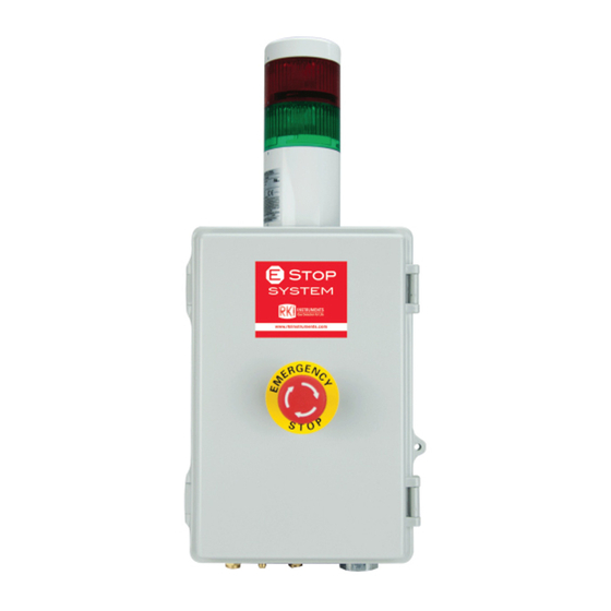
Summary of Contents for RKI Instruments 82-5223
- Page 1 82-5223 115 VAC Pneumatic ESTOP Operator’s Manual Part Number: 71-0572 Revision: P1 Released: 8/13/21 www.rkiinstruments.com...
- Page 2 Product Warranty RKI Instruments, Inc. warrants gas alarm equipment sold by us to be free from defects in materials, workmanship, and performance for a period of one year from the date of shipment from RKI Instruments, Inc. Any parts found defective within that period will be repaired or replaced, at our option, free of charge.
-
Page 3: Table Of Contents
About the 82-5223 ........ -
Page 4: Overview
Overview This manual describes the 82-5223 emergency shutoff. It also describes how to install and start up the device. A spare parts list at the end of this manual lists replacement parts. About the 82-5223 The 82-5223 is a fixed-mounted device with a solenoid valve, relay, power supply, stack light, and emergency stop button. -
Page 5: Description
One conduit hub on the bottom of the housing is for external wiring connections. Two compression fittings for 1/4 inch OD rigid tubing allow for compressed air to be routed to and from the 82-5223. One hose barb fitting for 1/4 inch ID flexible tubing allows for vented air to be routed away from the 82-5223, if desired. -
Page 6: Internal Description
CO NTA C TS Field Wiring Terminal Strip Figure 2: Internal Component Location Relay A DPDT relay installed on the right side of the 82-5223 controls the stack light’s LED color and also controls the power to the solenoid valve. 6 • 82-5223... -
Page 7: Installation
Solenoid Valve A 3-way solenoid valve installed on the left side of the 82-5223 controls the flow of connected compressed air. When the solenoid is energized, the pneumatic line between the 82-5223 and the connected pneumatic device is pressurized. When the solenoid de-energizes, it closes the “In” port and depressurizes the pnematic line between the 82-5223 and the connected pneumatic device through the vent port. - Page 8 4. Insert 3/16 in. screws through the mounting slots to secure the housing to the mounting surface. 7.19 Ø .23 x .3 slot, 4X 18.82 11.41 6.04 8.09 Figure 3: Outline & Mounting Dimensions 8 • 82-5223...
-
Page 9: Factory Wiring
Blac k Relay Blac k R ed Solenoid Power R ed Valve Supply Yell ow Emergency Stop R ed Button Contacts R ed R ed 1 N C T O ALARM CONT ACTS Figure 4: Factory Wiring 82-5223 • 9... -
Page 10: Field Wiring
82-5223 and the connected pneumatic device. If you do connect the 82-5223 to a remote relay contact, the relay contact set used must be normally open and the relay must be configured as normally energized. - Page 11 NOTE: If remote relay c ontac ts are n ot wired to the Field W iring Term inal Strip, l eav e the jum per i nstalled. Relay Contacts Figure 5: Field Wiring 11. Close the housing door. 82-5223 • 11...
-
Page 12: Making Tubing Connections
OD stainless steel, copper, or aluminum tubing. 3. For each of the 82-5223’s compression fittings, hold the fitting still using a 5/8 inch open-end wrench or an adjustable wrench and firmly tighten the nut with a 9/16 inch open-end wrench or an adjustable wrench so the ferrules crimp onto the tubing and make a seal. -
Page 13: Start Up
1. Be sure the emergency stop button is not pushed. If it is pushed, turn it clockwise to reset it. 2. Turn on the compressed air source, power to the 82-5223, and power to the device whose relay contact is wired to the 82-5223 (if used). -
Page 14: Replacing The Fuse
Replacing the Fuse 1. Turn off or disconnect power to the 82-5223. 2. Open the 82-5223 housing door. 3. Locate the fuse. It is in the power line shown below and is secured to the right side of the housing with a zip tie. -
Page 15: Parts List
Parts List Table 2 lists replacement parts and accessories for the 82-5223. Table 2: Parts List Part Number Description 43-4143RK Fuse, 5 mm x 20 mm, 250V, 1A, slow blow 51-0210 Stack light, red/green, steady 71-0572 82-5223 Operator’s Manual (this document)


Need help?
Do you have a question about the 82-5223 and is the answer not in the manual?
Questions and answers