
Related Manuals for RKI Instruments 65-2515RK


Summary of Contents for RKI Instruments 65-2515RK
- Page 1 65-2515RK Oxygen Detector Operator’s Manual Part Number: 71-0137RK Revision: B Released: 10/1/20 1.800.544.2843 www.calcert.com sales@calcert.com...
- Page 2 Typical calibration frequen- cies for most applications are between 3 and 6 months, but can be required more often or less often based on your usage. 2 • 65-2515RK Oxygen Detector 1.800.544.2843 www.calcert.com...
- Page 3 Product Warranty RKI Instruments, Inc. warrants gas alarm equipment sold by us to be free from defects in materials, workmanship, and performance for a period of one year from date of shipment from RKI Instruments, Inc. Any parts found defective within that period will be repaired or replaced, at our option, free of charge.
-
Page 4: Table Of Contents
Parts List ..............17 4 • 65-2515RK Oxygen Detector 1.800.544.2843... -
Page 5: Overview
NOTE: The following symbol on the detector label is a caution to the user to refer to this documentation for installation and operation instructions: WARNING: When using the 65-2515RK, you must follow the instructions and warnings in this manual to assure proper and safe operation of the 65-2515RK and to minimize the risk of personal injury. -
Page 6: Description
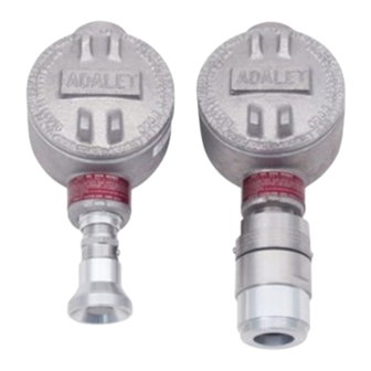
Description This section describes the components of the 65-2515RK. It consists of the oxygen detector and the junction box Oxygen Detector The oxygen detector consists of the detector housing and the plug-in sensor. Detector Housing Body Cap Gasket Oxygen Sensor... -
Page 7: Junction Box
Select a site where the detector is not likely to be bumped or disturbed. Make sure there is sufficient room to perform start-up, maintenance, and calibration procedures. • Select a site that is at normal breathing level. 65-2515RK Oxygen Detector • 7 1.800.544.2843 www.calcert.com sales@calcert.com... - Page 8 3.62 Figure 2: 65-2515RK Outline & Mounting Dimensions NOTE: The oxygen detector in the 65-2515RK is normally provided with an Adalet XIHSCFC3 junction box rated explosion proof for Class I, Groups B, C, and D. This combination is shown in Figure 2 above. Any junction box with an internal volume less than or equal to 69 cubic inches and rated explosion proof for Class I, Groups B, C, and D may be used for this detector.
-
Page 9: Wiring The Oxygen Detector
9. Connect the wires to the applicable controller terminal strip as shown in Figure 3 below. See the controller operator’s manual and the controller’s detector head specification sheet for wiring information specific to a controller. 65-2515RK Oxygen Detector • 9 1.800.544.2843 www.calcert.com... - Page 10 Figure 3: Wiring the Oxygen Detector to a Controller 10. If using shielded cable, connect the cable’s drain wire to an available chassis ground at the controller. RKI controllers typically have a ground stud that is a convenient grounding location. 10 • 65-2515RK Oxygen Detector 1.800.544.2843 www.calcert.com sales@calcert.com...
-
Page 11: Startup
RKI Instruments, Inc. recommends using a 0.5 LPM (liters per minute) fixed flow regulator. 1. Screw the calibration cup onto the bottom of the oxygen detector. -
Page 12: Maintenance
It includes daily and quarterly procedures. Daily Verify a display reading of 20.9% oxygen at the controller. Investigate significant changes in the reading. Quarterly Calibrate the detector as described in “Calibration” on page 15. 12 • 65-2515RK Oxygen Detector 1.800.544.2843 www.calcert.com sales@calcert.com... -
Page 13: Troubleshooting
5. Carefully plug the replacement sensor into the socket pattern that is located in the top section of the detector housing. NOTE: Match the sensor’s male pins with the two female sockets as you plug the sensor into the sockets. 65-2515RK Oxygen Detector • 13 1.800.544.2843 www.calcert.com sales@calcert.com... - Page 14 10. Turn on the controller. CAUTION: Allow the replacement detector to warm up for 5 minutes before you continue with the next step. 11. Calibrate the replacement detector as described in “Calibration” on page 15. 14 • 65-2515RK Oxygen Detector 1.800.544.2843 www.calcert.com sales@calcert.com...
-
Page 15: Calibration Frequency
It describes calibration using a calibration kit that includes a calibration cup, calibration gas, sample tubing, and a fixed flow regulator with an on/off knob. RKI Instruments, Inc. recommends using a 0.5 LPM (liters per minute) fixed flow regulator. -
Page 16: Setting The Zero Reading
2. Verify that the controller display reading increases and stabilizes at 20.9% oxygen. 3. Store the components of the calibration kit in a safe and convenient place. 16 • 65-2515RK Oxygen Detector 1.800.544.2843 www.calcert.com sales@calcert.com... -
Page 17: Parts List
Oxygen replacement detector assembly (includes plug-in sensor), CSA classified (does not include junction box) 65-2515RK Oxygen detector/junction box, CSA classified 71-0137RK 65-2515RK Oxygen Detector Operator’s Manual (this document) 81-0076RK-01 Zero air calibration cylinder, 34 liter steel 81-0078RK Calibration cylinder, 100% nitrogen, 17 liter...
Need help?
Do you have a question about the 65-2515RK and is the answer not in the manual?
Questions and answers