
Related Manuals for RKI Instruments CT-7 Series


Summary of Contents for RKI Instruments CT-7 Series
- Page 1 65-2302/65-2303 CT-7 Series Toxic Detector Operator’s Manual Part Number: 71-0422 Revision: H Released: 6/24/21 www.rkiinstruments.com...
- Page 2 WARNING Read and understand this instruction manual before operating detector. Improper use of the detector could result in bodily harm or death. Periodic calibration and maintenance of the detector is essential for proper operation and correct readings. Please calibrate and maintain this detector regularly! Frequency of calibration depends upon the type of use you have and the sensor types.
- Page 3 Product Warranty RKI Instruments, Inc. warrants gas alarm equipment sold by us to be free from defects in materials, workmanship, and performance for a period of one year from date of shipment from RKI Instruments, Inc. Any parts found defective within that period will be repaired or replaced, at our option, free of charge.
-
Page 4: Table Of Contents
Table of Contents Overview ..............5 Specifications . -
Page 5: Overview
Overview This manual describes the 65-2302 and 65-2303 toxic detectors. This manual also describes how to install, start up, maintain, and calibrate the toxic detector when used with a gas monitoring controller. A parts list at the end of this manual lists replacement parts and accessories for the toxic detector. -
Page 6: Description
Table 1: Specifications Sampling Method Diffusion Accuracy ± 10% of reading or ± 5% of full scale (whichever is greater) Response Time T90 in 60 seconds Operating Temperature & -4°F to 104°F (-20°C to 40°C) Humidity WARNING: When using the 65-2302/65-2303, you must follow the instructions and warnings in this manual to assure proper and safe operation of the 65-2302/ 65-2303 and to minimize the risk of personal injury. -
Page 7: 65-2302 Toxic Detector
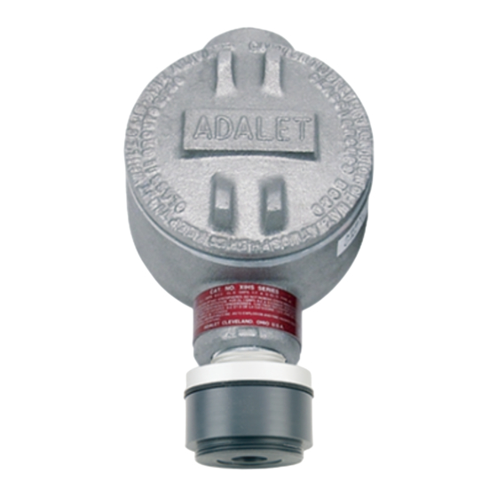
65-2302 Toxic Detector The 65-2302 toxic detector consists of the detector housing body, detector housing cap, cap gasket, and the plug-in sensor. Detector Housing Body (different for each detector type) Cap Gasket Plug-in Sensor (different for each detector type) VersaporR Membrane Detector Housing Cap Figure 2: 65-2302 Toxic Detector Component Location... -
Page 8: Installation
controller. Three spacers installed on the back of the junction box control the distance of the junction box from a mounting surface and ensure that there is enough room to install a calibration cup on the detector during calibration. A terminal block within the junction box facilitates the wiring connections. -
Page 9: Wiring The Toxic Detector To A Controller
NOTE: If your application does not require a specific mounting site, mount the detector at approximately breathing level. 3.10 3/4 NPT Conduit Hub 3/4" NPT 7.30 Rubber 3.65 Spacer, 3X 6.70 Max 1.22 Detector Ø 1.75 Junction 1 1/2-20 Thread for Calibration Cup 1 1/2-20 T hread for Calibration Cup... - Page 10 5. Guide a two-conductor, shielded cable or two wires in conduit through the unused conduit hub of the junction box. Use appropriate conduit fittings and construction technique for the environmental rating of the junction box. The junction box is rated NEMA 4X. 6.
-
Page 11: Startup
11. Reinstall the junction box cover. Start Up This section describes procedures to start up the toxic detector and place the detector into normal operation. Introducing Incoming Power 1. Complete the installation procedures described earlier in this manual. 2. Verify that the power wiring to the controller is correct and secure. Refer to the controller operator’s manual. -
Page 12: Maintenance
3. For a non-fresh air environment: a. Screw the calibration cup onto the bottom of the detector. b. Screw the regulator into the zero air calibration cylinder. c. Use the sample tubing to connect the regulator to the calibration cup. d. -
Page 13: Troubleshooting
Troubleshooting The troubleshooting guide describes symptoms, probable causes, and recommended action for problems you may encounter with the toxic detector. NOTE: This troubleshooting guide describes detector problems only. See the controller operator’s manual for problems you may encounter with the controller. Fail Condition Symptoms •... -
Page 14: Replacing Components Of The Toxic Detector
15. 5. If the calibration/response difficulties continue, replace the plug-in sensor as described later in this section. 6. If the calibration/response difficulties continue, contact RKI Instruments, Inc. for further instruction. Replacing Components of the Toxic Detector This section includes a procedure to replace the plug-in toxic sensor, the VersaporR membrane, and the entire toxic detector assembly. - Page 15 WARNING: The toxic sensor will not operate properly if the wire jumper is not removed. Remove jumper Figure 5: Plug-In Sensor Jumper Removal 6. Carefully plug the replacement sensor into the four-socket pattern located in the detector housing body. WARNING: You must replace the plug-in sensor with the same type of sensor that is installed.
- Page 16 8. Plug the sensor back into the four-socket pattern in the detector housing body. 9. Make sure the cap gasket is in place and screw the detector housing cap back onto the detector housing body. 10. Turn on power to the controller. 11.
-
Page 17: Calibration Frequency
Although there is no particular calibration frequency that is correct for all applications, a calibration frequency of every 3 months is adequate for most toxic detector applications. Unless experience in a particular application dictates otherwise, RKI Instruments, Inc. recommends a calibration frequency of every 3 months for the toxic detector. -
Page 18: Calibration
RKI Instruments, Inc. recommends using a ClO generator to set the ClO detector’s response reading. The flow rate on the generator needs to be set to 0.5 LPM and RKI Instruments, Inc. recommends that 0.5 ppm ClO be used. If a ClO generator is used for calibration, the steps related to the use of a calibration gas cylinder in the instructions below can be disregarded. -
Page 19: Setting The Zero (Fresh Air) Reading
Setting the Zero (Fresh Air) Reading 1. Follow the instructions in the controller operator’s manual for setting the zero reading. 2. When the instructions call for applying zero air to the detector, turn the regulator’s on/off knob counterclockwise to open it. Gas will begin to flow. 3. -
Page 20: Returning To Normal Operation
Returning to Normal Operation 1. Allow about 45 seconds for the gas reading to decrease below the alarm points and then return the controller to normal operation. NOTE: If you do not allow the gas reading to decrease below the alarm points, then unwanted alarms may occur. - Page 21 Table 2: Parts List Part Number Description 65-2302-NH3-5 Replacement detector assembly, NH , 0 - 500 ppm range (includes plug-in sensor) 65-2302-NH3-75 Replacement detector assembly, NH , 0 - 75 ppm range (includes plug-in sensor) 71-0422 65-2302/65-2303 Operator’s Manual (this document) 81-0076RK Zero air calibration cylinder, 17 liter 81-0076RK-01...
Need help?
Do you have a question about the CT-7 Series and is the answer not in the manual?
Questions and answers