Campbell CS650 User Manual
Soil water content reflectometers
Hide thumbs
Also See for CS650:
- Instruction manual (56 pages) ,
- Instruction manual (59 pages) ,
- Product manual (55 pages)
Table of Contents
Advertisement
Quick Links
Download this manual
See also:
Instruction Manual
Advertisement
Table of Contents

Related Manuals for Campbell CS650


Summary of Contents for Campbell CS650
- Page 1 CS650 & CS655 Soil Water Content Reflectometers Issued: 24.6.15 Copyright © 2011-2015 Campbell Scientific, Inc. Printed under licence by Campbell Scientific Ltd. CSL 912...
- Page 3 Quotations for repairs can be given on request. It is the policy of Campbell Scientific to protect the health of its employees and provide a safe working environment, in support of this policy a “Declaration of Hazardous Material and Decontamination”...
-
Page 5: About This Manual
PLEASE READ FIRST About this manual Please note that this manual was originally produced by Campbell Scientific Inc. primarily for the North American market. Some spellings, weights and measures may reflect this origin. Some useful conversion factors: Area: 1 in (square inch) = 645 mm 1 lb (pound weight) = 0.454 kg... - Page 7 • Periodically (at least yearly) check electrical ground connections. WHILE EVERY ATTEMPT IS MADE TO EMBODY THE HIGHEST DEGREE OF SAFETY IN ALL CAMPBELL SCIENTIFIC PRODUCTS, THE CUSTOMER ASSUMES ALL RISK FROM ANY INJURY RESULTING FROM IMPROPER INSTALLATION, USE, OR MAINTENANCE OF TRIPODS, TOWERS, OR ATTACHMENTS TO TRIPODS AND TOWERS...
-
Page 9: Table Of Contents
Contents PDF viewers: These page numbers refer to the printed version of this document. Use the PDF reader bookmarks tab for links to specific sections. 1. Introduction ..............1 2. Cautionary Statements ..........1 3. Initial Inspection ............1 4. Quickstart ..............2 5. - Page 10 CR1000 Programs ................B-1 B.1.1 CR1000 with One CS650 Probe ..........B-1 B.1.2 CR1000 with Two CS650 Probes on Same Control Port ..B-1 B.1.3 CR1000 with 12 CS650 Probes on Multiplexer ......B-2 CR200X with Three CS650 Probes ..........B-3 C.
- Page 11 Size Specifications ................6 6-2. Relative Dielectric Permittivity Specifications ........8 7-1. CS650 Wiring Code for SDI-12 ............11 8-1. CS650 Wiring Code for RS-232 and A200 ........13 8-2. Real-Time Measurements ..............16 8-3. CS650 Terminal Commands .............. 18 8-4.
-
Page 13: Introduction
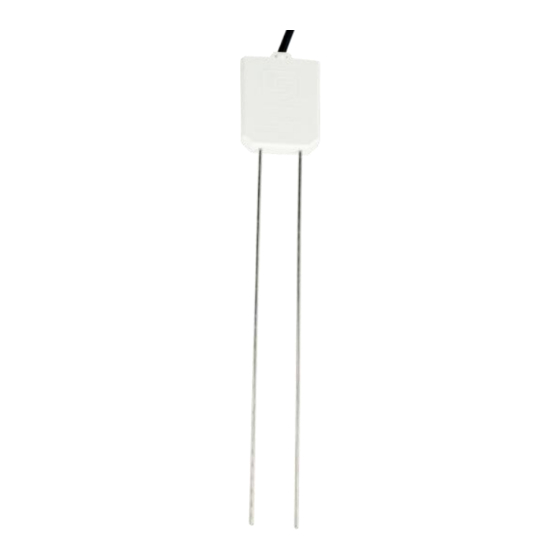
They output an SDI-12 signal that many of our dataloggers can measure. The CS650 has 30 cm length rods, whereas the CS655 has 12 cm length rods. This manual uses CS650 to reference model numbers CS650 and CS655. Unless specifically stated otherwise, information in the manual applies equally to both models. -
Page 14: Quickstart
CS650 and CS655 Water Content Reflectometers Quickstart Short Cut is an easy way to program your datalogger to measure the CS650 and assign datalogger wiring terminals. The following procedures show using Short Cut to program the CS650. Install Short Cut by clicking on the install file icon. Get the install file from either www.campbellsci.com, the ResourceDVD, or find it in installations of... - Page 15 Meteorological | Soil Moisture | CS650/CS655 Water Content Reflectometer. Four options are available that monitor different parameters. In this tutorial, we’ll select CS650/CS655 Water Content Reflectometer (VWC, EC, T, P, PA, and VR). Click to move the selection to the Selected device window.
-
Page 16: Overview
6, check the output of the sensor in the datalogger support software data display to make sure it is making reasonable measurements. Overview The CS650 measures volumetric water content, electrical conductivity, dielectric permittivity, and temperature of soils or other porous media. These values are reported through SDI-12 communication. -
Page 17: Cs650 Water Content Reflectometer
Volumetric water content information is derived from the probe’s sensitivity to the dielectric permittivity of the medium surrounding the probe stainless-steel rods. The CS650 is configured as a water content reflectometer, with the two parallel rods forming an open-ended transmission line. A differential oscillator circuit is connected to the rods, with an oscillator state change triggered by the return of a reflected signal from one of the rods. -
Page 18: Specifications
Campbell Scientific also offers the CS650-LC, CS655-LC, and CWS655. The CS650-LC and CS655-LC include a connector for attaching the sensor to an ET107 weather station. The CWS655 is a wireless version of our CS655; refer to the Wireless Sensor Network manual for more information. -
Page 19: Electrical Specifications
Compatibility: criteria available upon request) Meets EN61326 requirements for protection against electrostatic discharge and surge External RF sources can affect CS650 measurements. CS650 circuitry should be located away from radio transmitter aerials and cables, or measurements ignored during RF transmissions. -
Page 20: Operational Specifications
Figure 6-1. CS650 and CS655 average current drain Figure shows average current drain for different measurement rates and quantities of CS650 probes. If the time between measurements is five minutes or longer, average current drain may be approximated at 0.15 milliamps per sensor. Operational Specifications Table provides the operational specifications. -
Page 21: Installation
The CS650 measures the bulk dielectric permittivity, average volumetric water content, and bulk EC along the length of the rods, which is 30 cm for the CS650 and 12 cm for the CS655. The probe rods may be inserted vertically into the soil surface or buried at any orientation to the surface. -
Page 22: Proper Insertion
Datalogger Wiring Our dataloggers typically use SDI-12 to measure the sensor because RS-232 communication requires more control ports per CS650 and RS-232 programming is more complicated than SDI-12 programming. SDI-12 communication also allows up to ten probes to be given different addresses and then share a single... -
Page 23: Programming
User Manual Table shows the SDI-12 wiring for the CS650 water content reflectometer. SDI-12 data is transmitted to a CRBasic datalogger odd numbered control port or U terminal. Wiring information for RS-232 communications is provided in Section 8.1.1.2, RS-232 Wiring (p. -
Page 24: Operation
SDI12Recorder(Destination, SDIPort, SDIAddress, “SDICommand”, Multiplier, Offset) Operation A200 and Device Configuration Utility The A200 Sensor-to-PC Interface allows communication between a CS650 and a PC, allowing sensor settings to be changed through Device Configuration Utility (DevConfig) software. 8.1.1 Using the A200 8.1.1.1 Driver Installation... -
Page 25: Powering The Sensor
DevConfig may be downloaded from the Campbell Scientific website, www.campbellsci.com/downloads. Connect the CS650 to the A200 as shown in Table 8-1. Connect the PC to the A200 USB port with the supplied USB cable. Launch DevConfig and select CS650 Series from the Device Type menu on the... - Page 26 Select the appropriate PC serial port from the list of available COM ports shown when the browse button on the lower left is selected (see Section 8.1.1.4, Determining which COM Port the A200 has been Assigned (p. 13) Select Ok and then Connect to begin communication with the CS650.
-
Page 27: Settings Editor Tab
Default communication settings are 9600 baud, no parity, 1 stop bit, 8 data bits, and no error checking. After any changes to CS650 settings, select Apply to write the changes to the CS650 firmware. A configuration summary is then shown. -
Page 28: Send Os Tab
Voltage Ratio 8.1.2.2 Send OS Tab The Send OS tab is used to update the firmware in the CS650. The firmware is available at www.campbellsci.com/downloads. The file to send will have a filename extension of .a43, such as CS65X.Std.00.36.a43. Sending a new operating system will not affect any of the user-modified settings or probe specific multiplier and offset settings. -
Page 29: Terminal Tab
To download a new operating system, follow the Operating System Download Procedure listed on the Send OS tab. 8.1.2.3 Terminal Tab The Terminal tab may be used to send serial commands directly to the CS650. See Table for a list of serial interface commands. -
Page 30: Cs650 Terminal Commands
CS650 and CS655 Water Content Reflectometers Table 8-3. CS650 Terminal Commands Command Values Returned Units 1) Volumetric Water Content, 2) Electrical Conductivity, dS/m °C 3) Temperature 1) Permittivity, 2) Electrical Conductivity, dS/m °C 3) Temperature 1) Period, ... -
Page 31: Sdi-12 Measurements
CampbellSci, OS version, Product Serial Number Up to 10 CS650 probes may be connected to the same datalogger control port as long as each one has a unique SDI-12 address. The CS650 ships with a default SDI-12 address of 0 unless otherwise specified at the time of ordering. The SDI- 12 address may be changed through DevConfig software (see Section 8.1, A200... -
Page 32: Water Content Reflectometer Method For Measuring Volumetric Water Content
Failure to turn off the switched 12 volt channel before clocking CAUTION the multiplexer will result in damage to the multiplexer relays. The proper sequence in the datalogger program for measuring CS650 probes on a multiplexer is: Set RES control port high to enable multiplexer... -
Page 33: Electrical Conductivity
It has been shown in numerous research efforts that this equation works well in most mineral soils, so a soil specific calibration of the CS650 probe is usually not necessary. If a soil specific calibration is desired, the user can generate an to ... -
Page 34: Temperature Correction Of Soil Electrical Conductivity
CS650 and CS655 Water Content Reflectometers 8.3.3.2 Temperature Correction of Soil Electrical Conductivity The EC value reported by the CS650 is bulk electrical conductivity. This value is temperature dependent, changing by 2% per degree Celsius. To compensate for the effect of temperature, EC readings may be converted to a standard temperature, such as 25 °C using the following equation:... -
Page 35: Accurate Soil Temperature Measurement
1.55 g cm may require a media-specific calibration equation. In these cases, the user may develop a calibration equation to convert CS650 permittivity to volumetric water content over the range of water contents the probe is expected to measure. -
Page 36: Collecting Laboratory Data For Calibration
8.4.3 Collecting Laboratory Data for Calibration Water content reflectometer data needed for CS650 calibration are the CS650 permittivity reading and an independently determined volumetric water content. From this data, the probe response to changing water content can be described by a linear or polynomial function as described in Section 8.4.2, User-Derived... - Page 37 Equilibration can be verified by frequently observing the CS650 permittivity output. When permittivity is constant, equilibration is achieved. Collect a set of calibration data values and repeat the water addition procedure again if needed.
-
Page 38: Collecting Field Data For Calibration
However, intentionally changing water content in soil profiles can be difficult. A vertical face of soil can be formed with a shovel. If the CS650 is to be used within about 0.5 metres of the surface, the probe can be inserted into the face and water added to the surface with percolation. -
Page 39: Calculations
bulk The average water content for the replicates and the recorded CS650 period are one datum pair to be used for the calibration curve fit. 8.4.5 Calculations The empty cylinders used for core sampling should be clean and both empty mass and volume are measured and recorded. - Page 40 CS650 and CS655 Water Content Reflectometers To obtain m , weigh the tray containing the soil after drying. Subtract tray mass . Calculate gravimetric water content, for m , using To obtain soil bulk density, use ...
-
Page 41: Maintenance And Troubleshooting
User Manual Maintenance and Troubleshooting The CS650 does not require periodic maintenance. Table provides troubleshooting information. Table 9-1. Symptom, Cause, and Solutions Symptom Possible Cause Solution All CS650 output No SDI12Recorder Add SDI12Recorder instruction in datalogger instruction to datalogger values read 0... -
Page 42: References
CS650 and CS655 Water Content Reflectometers 10. References Ledieu, J., P. De Ridder, P. De Clerck, and S. Dautrebande. 1986. “A method of measuring soil moisture by time-domain reflectometry,” J. Hydrol. 88:319- 328. Rhoades, J.D., P.A.C. Raats, and R.J. Prather. 1976. Effects of liquid-phase electrical conductivity, water content and surface conductivity on bulk soil electrical conductivity. -
Page 43: Importing Short Cut Code Into A Program Editor
Appendix A. Importing Short Cut Code into a Program Editor This tutorial shows: How to import a Short Cut program into a program editor for additional refinement How to import a wiring diagram from Short Cut into the comments of a custom program Short Cut creates files that can be imported into either CRBasic Editor program editor. - Page 44 Appendix A. Importing Short Cut Code...
-
Page 45: Example Programs
The first CS650 has an SDI-12 address of 0 and the second has an address of 1. Wiring for the example is shown in Table B-2. Assignment of aliases and units is not shown in this example. -
Page 46: Cr1000 With 12 Cs650 Probes On Multiplexer
NextScan EndProg B.1.3 CR1000 with 12 CS650 Probes on Multiplexer This CRBasic example program measures 12 CS650 probes on a AM16/32B multiplexer every 15 minutes, storing hourly averages of volumetric water content, electrical conductivity, soil temperature, permittivity, period average, and voltage ratio. -
Page 47: Cr200X With Three Cs650 Probes
NextScan EndProg B.2 CR200X with Three CS650 Probes This CRBasic example program measures three CS650 probe on a CR200X every 15 minutes, storing hourly averages of volumetric water content, electrical conductivity, soil temperature, permittivity, period average, and voltage ratio. The CS650s have SDI-12 addresses of 0, 1, and 2, respectively. - Page 48 Appendix B. Example Programs 'CS650 #1 SDI12Recorder (CS650(1),"0M3!",1,0) 'CS650 #2 SDI12Recorder (CS650(7),"1M3!",1,0) 'CS650 #3 SDI12Recorder (CS650(13),"2M3!",1,0) SWBatt (0 ) 'Remove power from CS650's CallTable CS650 'Call Data Table NextScan EndProg...
-
Page 49: C. Discussion Of Soil Water Content
Appendix C. Discussion of Soil Water Content The water content reflectometer measures volumetric water content. Soil water content is expressed on a gravimetric and a volumetric basis. To obtain the independently determined volumetric water content, gravimetric water content must first be measured. Gravimetric water content (g) is the mass of water per mass of dry soil. - Page 50 Discussion of Soil Water Content...
-
Page 51: Sdi-12 Sensor Support
Sensors with the –VS option are addressed with the last digit of the probe’s serial number. This allows for multiple CS650’s to be connected to a single control port without requiring the user to change the SDI-12 addresses from zero. - Page 52 Start Measurement Command (aMv!) Qualifier v is a variable between 1 and 3 that requests variant data. Variants include different subsets of the CS650 probe output: Volumetric Water Content (Bulk Electrical Conductivity (Temperature (°C) Permittivity (Bulk Electrical Conductivity (Temperature (°C) Period (Voltage Ratio (Temperature (°C)
-
Page 53: Changing The Sdi-12 Address Using Terminal Emulator And A Datalogger
D.2 Changing the SDI-12 Address Using Terminal Emulator and a Datalogger Up to ten CS650’s or other SDI-12 sensors can be connected to a single datalogger control port. Each SDI-12 device on the same control port must have a unique SDI-12 address. -
Page 54: Cr200(X) Series Datalogger Example
SDI12 <enter>. The response “SDI12>” indicates that the CS650 is ready to accept SDI-12 commands. To query the CS650 for its current SDI-12 address, key in ?! <enter> and the CS650 will respond with its SDI-12 address. If no characters are typed within 60 seconds, then the mode is exited. -
Page 55: Cr1000 Datalogger Example
At the “CR1000>” prompt, make sure the All Caps Mode box is checked and enter the command SDI12 <enter>. At the “Enter Cx Port 1, 3, 5, or 7” prompt, key in the control port number where the CS650 green lead is connected and <enter>. The response “Entering SDI12 Terminal” indicates that the CS650 is ready to accept SDI-12 commands. - Page 56 CAMPBELL SCIENTIFIC COMPANIES Campbell Scientific, Inc. (CSI) 815 West 1800 North Logan, Utah 84321 UNITED STATES www.campbellsci.com info@campbellsci.com Campbell Scientific Africa Pty. Ltd. (CSAf) PO Box 2450 Somerset West 7129 SOUTH AFRICA www.csafrica.co.za sales@csafrica.co.za Campbell Scientific Australia Pty. Ltd. (CSA)
Need help?
Do you have a question about the CS650 and is the answer not in the manual?
Questions and answers