Table of Contents
Advertisement
Advertisement
Table of Contents

Subscribe to Our Youtube Channel
Related Manuals for Focusrite Rednet R1


Summary of Contents for Focusrite Rednet R1
- Page 1 User Guide www.focusrite.com FFFA002119-01...
-
Page 2: Table Of Contents
................REDNET R1 CONTROLS AND CONNECTIONS . -
Page 3: About This User Guide
About this User Guide This user guide applies to the RedNet R1. It provides information about installing and using the unit, and how it can be connected into your system. Dante® and Audinate® are registered trademarks of Audinate Pty Ltd. -
Page 4: Introduction
Thank you for purchasing the Focusrite RedNet R1. RedNet R1 is a hardware monitor controller and headphone output device. RedNet R1 controls Focusrite audio-over-IP devices such as Red 4Pre, Red 8Pre, Red 8Line and Red 16Line monitor sections. RedNet R1 has the capability to control the mic pres of the Red interfaces. -
Page 5: Rednet R1 Controls And Connections
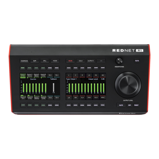
REDNET R1 CONTROLS AND CONNECTIONS Top Panel 1 Function Keys Eight keys select the device’s operating mode, recall submenus and access system settings. See page 10 for additional information. • Headphone allows source selection for the local headphone output • Sum switches the selection mode for multiple sources from inter-cancel to summed;... - Page 6 Top Panel . . . 5 Headphone Level Pot Controls the volume level sent to the stereo headphone jack on the rear panel. 6 Headphone Mute Switch Latching switch mutes the audio going to the headphone jack. 7 Output Level Encoder Controls the volume level sent to the selected monitors.
- Page 7 Preset Switch . . . To store a preset level: • Press the Preset switch • Screen 2 displays current level and the stored values for presets 1 & 2. N/A indicates that a preset value has not previously been stored •...
-
Page 8: Rear Panel
8 Headphone Socket Standard 1/4” stereo jack for headphones. *For health and safety reasons, and to ensure that the levels are not dangerous, do not power-up RedNet R1 while monitoring through headphones, or you may hear a loud “thump”. Refer to the Appendix on page 21 for the connector pinouts. -
Page 9: Physical Characteristics
PoE injectors used should be Gigabit capable. To use the 12V DC input, connect the external plugtop PSU supplied to an adjacent mains outlet. Only use the DC PSU supplied with RedNet R1. Use of other external supplies may affect performance or might damage the unit. -
Page 10: Rednet R1 Operation
*It is important that the firmware update procedure is not interrupted – either by switching off power to the RedNet R1 or the computer on which RedNet Control is running, or by disconnecting either from the network. From time to time Focusrite will release firmware updates within new versions of RedNet Control. -
Page 11: Mode
Function Keys . . . Spill Expands a source to show its component channels allowing them to be muted/un-muted individually: • Select a source to spill • Screen 1 will display the (up to) 12 channels contained within that source: °... -
Page 12: Mute
Function Keys . . . Settings – Accesses the Global Settings submenu: • Talkback Latch – Toggles the action of the talkback buttons between momentary and latching • Auto Standby – When active, will cause the TFT screens to turn off after 5 mins of inactivity, ie., no metering changes, switch presses or pot movements. -
Page 13: Rednet Control 2
REDNET CONTROL 2 RedNet Control 2 is Focusrite’s customisable software application for controlling and configuring RedNet, Red and ISA range of interfaces. Graphical representation for each device shows: control levels, function settings, signal meters, signal routing and mixing – as well as providing status indicators for power supplies, clock and the primary/secondary network connections. -
Page 14: Input Channel Configuration
Source Groups . . . Input Channel Configuration Click the drop-down below each Source Group button to assign its channel configuration. Two options are available: • Presets – Select from the list of predefined channel configurations: - Mono - 5.1.2 - Stereo - 5.1.4 - LCR... -
Page 15: Monitor Outputs
Outputs . . . Monitor Outputs The Monitor Outputs page is used to configure the output groups and to assign audio channels. Output Type Selection Click each drop-down to assign its output configuration: - Mono - 5.1.2 - Stereo - 5.1.4 - LCR - 7.1.2 - 5.1... -
Page 16: Channel Mapping
Channel Mapping The Channel Mapping page displays the cross-point grid for each Source Group/Output Destination selection. Individual cross-points can be selected/deselected or level trimmed. • The number of rows displayed corresponds to the number of channels in each Source Group •... -
Page 17: Talkback
Talkback The Talkback page displays the settings of the cross-point grid for the talkback Output selection and the headphone settings. Talkback Routing The routing table allows the user to route a single Talkback channel to 16 locations; the destination type is shown above the table. Talkback 1–4 can also be sent to Cue mixes 1–8. -
Page 18: Cue Mixes
Cue Mixes The Cue Mixes page shows the source, routing and level settings for each of the eight mix outputs. Mix output selection is shown above the list of available sources. Use CMD+’click’. to select multiple Output Destinations. Up to 30 sources can be selected as mixer inputs. ID (Identification) Clicking on the ID icon will identify the physical device being controlled by flashing its front panel... -
Page 19: Tools Menu
Tools Menu Clicking on the Tools icon will bring up the System Settings window. Tools are split across two tabs, ‘Device’ and ‘Footswitch’: Device: Preferred Master – On/Off state. Talkback Routing – Select the channel on a Red device to use as the talkback input. Headphone Routing –... - Page 20 Tools Menu . . . Footswitch: Assignment – Select the action of the footswitch input. Choose either: • The talkback channel(s) to activate, or... • the Monitor channel(s) to be muted •...
-
Page 21: Appendices
APPENDICES 1. Connector Pinouts Network (PoE) Cat 6 Core PoE A PoE B Connector type: RJ-45 receptacle White + Orange Orange White + Green Blue White + Blue Green White + Brown Brown Signal Talkback Screen Connector type: XLR-3 female Hot (+ve) Cold (–ve) Signal... -
Page 22: I/O Level Information
Appendices . . . 2. I/O Level Information Both the R1 and the Red range device under control are able to adjust the volume of the loudspeakers connected to the Red device’s analogue outputs. Having two control locations on the monitor system could result in there being either insufficient range or high sensitivity of the R1’s Output Level encoder. -
Page 23: Performance And Specifications
PERFORMANCE AND SPECIFICATIONS Headphone Output All measurements taken at +19dBm reference level, maximum gain, R = 600Ω 0 dBFS Reference Level +19 dBm, ±0.3 dB Frequency Response 20 Hz – 20 kHz ±0.2 dB THD + N -104 dB (<0.0006%) at -1 dBFS Dynamic Range 119 dB ‘A’-weighted (typical), 20 Hz - 20 kHz Output Impedance... - Page 24 You can contact our dedicated RedNet Customer Support team free of charge: Email: proaudiosupport@focusrite.com Phone (UK): +44 (0)1494 836384 Phone (USA): +1 (310) 450-8494 Troubleshooting If you are experiencing problems with your RedNet R1, we recommend that in the first instance, you visit our Support Answerbase at: www.focusrite.com/answerbase...
Need help?
Do you have a question about the Rednet R1 and is the answer not in the manual?
Questions and answers