Advertisement
Advertisement

Subscribe to Our Youtube Channel
Related Manuals for Titan 3PTTRIM


Summary of Contents for Titan 3PTTRIM
- Page 1 3PT Trimmer Owner’s Manual MPN: 3PTTRIM SKU: 191441...
-
Page 2: Table Of Contents
Table of Contents General Warnings.................... 3 Controls and Features Identification ..............6 Specification ....................7 Assembly Instructions ..................7 Operation Instructions ................... 13 Maintenance and Storage ................14 Troubleshooting ..................... 16 Parts Drawing & Parts List ................17... -
Page 3: General Warnings
GENERAL WARNINGS READ and UNDERSTAND the manual completely before using 3-POINT HITCH TRIMMER/MOWER. Become familiar with the operation and service recommendations to ensure the best performance from your machine. DANGER YOUR 3-POINT HITCH TRIMMER is driven by a PTO shaft that transfers power from your Tractor. The Tractor and PTO shaft are extremely dangerous and can cause serious injury or death if not used properly. - Page 4 ● Avoid wearing loose clothing or jewelry, which can catch on the machine’s moving parts. ● We recommend wearing gloves while using this machine. Be sure your gloves fit properly and do not have loose cuffs or drawstrings. ● Wear shoes with non-slip treads when using your 3PT Trimmer. Safety shoes are recommended. Do not use the machine while barefoot or wearing sandals with exposed toes or heels.
- Page 5 from the Tractor, then wait five minutes before performing any maintenance procedure or inspection on the Trimmer. ● Be mindful of hazards, changes in terrain, slopes, or wet conditions. Use care when backing up. ● Stop the cutting cords when crossing gravel drives, walks, or roads. ●...
-
Page 6: Controls And Features Identification
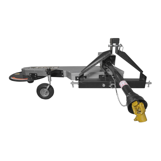
Controls and Features Identification It may be helpful to familiarize yourself with the controls and features of your 3-POINT HITCH TRIMMER/MOWER as shown in Figure 1 before beginning these procedures. -
Page 7: Specification
Specifications Tractor Requirements Category 1, 25 to 45 HP Max. Drive Tractor PTO PTO Speed 540 PRM Number of Trimmer Cords Belt A-2565 V-Belt Belt Adjustment Spring Loaded Idler Pulley Max. Wheel Base (distance from outside to 80” Outside of rear wheels) Cutting Height 5 Heights, 1.5”... - Page 8 STEP 2: Attach the Trimmer/Mower to the 3-Point Bracket 1. Slide the pivot pin into the mounting hole of the 3-point bracket, then fixed with locking ring and drive pin. 2. Insert the hex bolt M18x240 to the 3-point bracket and fixed with hex nut M18. 3.
- Page 9 STEP 4: Calculating length of PTO Shaft needed The PTO Shaft provided with your Trimmer is 32” overall compressed length and will work “as is” for most applications. Before you install the PTO shaft it is good practice to calculate optimum PTO shaft length according to your tractor and usage needs to determine if modifications are needed.
- Page 10 cords installed and/or at the same length will cause excessive vibration and could damage the machine. 1. Insert the end of a trimmer cord into the inlet hole (large slotted cutout) push it in until the end protrudes out the other side approximately 10mm. 2.
- Page 11 STEP 6: Cord Head Adjustment Note: The cord head can be located above or below the molded spacer giving you a 1-1/2” range in trimming height. The following steps show moving the cord head from below the molded spacer to on top of the molded spacer.
- Page 12 STEP 7: Greasing the Wheel Support Tools needed: ● Flexible hose grease gun ● Lithium grease ● Clean cloth Apply a quality general-purpose lithium grease with a hand-pumped grease gun to each of the support grease fitting. Support Grease Fitting...
-
Page 13: Operation Instructions
Operation Instructions WARNING ● This machine is designed to operate at 540 rpm PTO shaft speed only! Never operate at a faster speed; doing so can cause serious injury to the operator or bystanders and could cause damage to the machine that is not covered under warranty. -
Page 14: Maintenance And Storage
Engaging the Trimmer Head 1. Ensure that the trimmer is lowered to the ground and all guards are in place and properly secured before using. 2. Set tractor throttle at IDLE and engage the PTO. 3. Increase tractor throttle to the RPM’s required to obtain 540 PTO speed. Note: See your tractor manual for detailed information on tractor operation. - Page 15 Maintenance Position Many maintenance procedures can be performed easier by positioning the trimmer in an upright “maintenance” position. This position is for maintenance purposes only. Do not transport or operate the trimmer in the upright position. WARNING ● Two people are required when setting the trimmer body to the maintenance position. One person must steady the trimmer as the other installs the bolt.
-
Page 16: Troubleshooting
Troubleshooting Most problems are easy to fix. Consult the troubleshooting table below for common problems and their solutions. WARNING Disengage PTO, shut down the tractor engine, remove the key, wait for all moving parts to come to a complete stop, disconnect the PTO shaft from the tractor, then wait five minutes before performing any maintenance procedure or inspection on the trimmer. -
Page 17: Parts Drawing & Parts List
Parts Drawing & Parts List... - Page 18 Parts Drawing & Parts List Ref# Drawing No. Description TS600-02000 Base 9604-30305 Single Row Taper Roller Bearing TS600-00003 Spacer B TS600-00004 Articulating Bracket A TS600-00005 Articulating Bracket B 9101-10040-DX8.8 Hex Bolt M10x40 9301-1000-DX Flat Washer Ø10 TS6000-03000 Gearbox Fixed Frame 9215-10000-DX8.8 Hex Flange Lock Nut M10 TS600-01000...
- Page 19 Parts Drawing & Parts List Ref# Drawing No. Description 9101-10125-8.8DX Hex Bolt M10x125 Flat Key 8x7x32 9101-10025-DX Hex Bolt M10x25 TS600-00010 Spring Holder Base TS600-13000 Belt Adjustment Plate 9101-10065-8.8Q Hex Bolt M10x65 9206-10000-DX8.8 Hex Lock Nut M10 TS600-00008 Pulley Ø190 TS600-07000 Rotor Bearing 9603-6203-2RS...
- Page 20 Parts Drawing & Parts List Ref# Drawing No. Description 9103-05024-DX8.8 Hex Socket Countersunk Head Screw M5x24 TS600-00001 Hex Bolt M8x25 TS600-06000 Deflector Guard 9101-08030-DX8.8 Hex Bolt M8x30 TS600-00022 Connecting Plate TS600-05000 Wheel Stand 9701-06000 Oil Cup TS600-00023 Nylon Bushing TS600-10000 Wheel Caster TS600-00024 Spacer...
Need help?
Do you have a question about the 3PTTRIM and is the answer not in the manual?
Questions and answers