Table of Contents
Advertisement
Advertisement
Table of Contents

Related Manuals for Subaru EH09-2D


Summary of Contents for Subaru EH09-2D
-
Page 2: Table Of Contents
CONTENTS Section Title Page 1. SPECIFICATIONS ............1 2. -
Page 3: Specifications
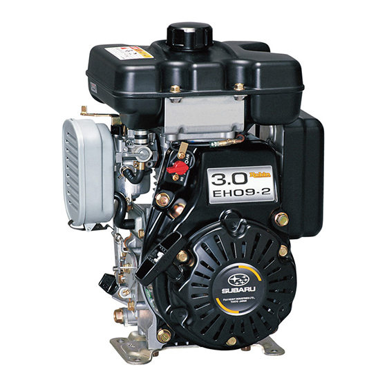
1. SPECIFICATIONS MODEL EH09-2D Air-Cooled, 4-Cycle, Single-Cylinder, Type Horizontal P.T.O. Shaft, OHV, gasoline engine Bore x Stroke mm (in.) 51 x 42 (2.01 x 1.65) Piston Displacement ml (cu.in.) 86 (5.25) Compression Ratio Maximum Output kW (HP) / r.p.m. 2.1 (2.9) / 4200 Continuous Output kW (HP) / r.p.m. -
Page 4: Disassembly And Reassembly
2. DISASSEMBLY AND REASSEMBLY 2-1 DISASSEMBLY PROCEDURES Step Parts to remove Remarks and procedures Fasteners Engine oil drain (1) Remove oil drain plug and drain oil. 14 mm spanner (2) To discharge oil quickly, remove oil gauge. Recoil starter Remove recoil starter from blower housing. M6 x 8 : 3 pcs. - Page 5 Step Parts to remove Remarks and procedures Fasteners Fuel tank (1) Close the fuel cock. (2) Disconnect fuel pipe between carburetor and fuel cock from carburetor. (3) Remove the fuel tank from the fuel tank M6 x 12 : 4 pcs. bracket.
- Page 6 Step Parts to remove Remarks and procedures Fasteners Air cleaner (1) Detach cleaner cover, and take out element and retainer. (2) Remove breather pipe from cleaner case and breather cover. (3) Remove cleaner case. M6 flange nut : 2 pcs. Be careful not to lose air cleaner gasket.
- Page 7 Step Parts to remove Remarks and procedures Fasteners Governor lever (1) Loosen the bolt and remove governor lever. M6 x 25 : 1 pc. 10 mm box spanner (2) Unhook governor spring from governor lever. Mark the hole on which the governor spring is hooked.
- Page 8 Step Parts to remove Remarks and procedures Fasteners Ignition coil Remove ignition coil from crankcase. M6 x 25 : 2 pcs. 10 mm box spanner Flywheel (1) Remove the starter pulley from flywheel. M14 nut, springwasher : 1 pc. Place socket wrench on flywheel fastening M6 x 12 : 4 pcs.
- Page 9 Step Parts to remove Remarks and procedures Fasteners Rocker cover Remove rocker cover and gasket from M6 x 30x 10 : 4 pcs. 10 mm box spanner cylinder head. Cylinder head (1) Remove cylinder head and gasket from M8 x 60 : 1 pcs. M8 x 55 : 1 pcs.
- Page 10 Step Parts to remove Remarks and procedures Fasteners Breather Remove breather cover, breather plate, and M6 x 12 : 2 pcs. 10 mm box spanner gasket from crankcase. Main bearing cover Be careful not to damage the oil seal. M6 x 28 : 8 pcs. Use a soft hammer and evenly tap around soft hammer outer surface of cover.
- Page 11 Step Parts to remove Remarks and procedures Fasteners Camshaft and tappets Lay carnkcase on the flywheel side push tappets up into the block and remove camshaft. Be careful not to damage camshaft and tappets. P.T.O. shaft side TAPPET STEP 18 CAMSHAFT CAMSHAFT –...
- Page 12 Step Parts to remove Remarks and procedures Fasteners Connecting rod and (1) Remove connecting rod bolts and connecting M5 x 25 : 2 pcs. rod cap. 8 mm box spanner piston (2) Turn crankshaft until piston comes to top dead center, push out connecting rod and piston assembly through top of cylinder.
- Page 13 Step Parts to remove Remarks and procedures Fasteners Crankshaft Tap lightly on flywheel end of crankshaft with soft hammer a soft hammer to remove from crankcase. * Be careful not to damage oil seal. P.T.O. shaft side STEP 20 CRANKSHAFT –...
- Page 14 Step Parts to remove Remarks and procedures Fasteners Intake and (1) Press down the spring retainer, take out collet 10 mm spanner Hexagon wrench exhaust valves valve, and then remove spring retainer and valve spring. (2) Remove intake and exhaust valves from cylinder head.
-
Page 15: Tightening Torque Chart
2-2 TIGHTENING TORQUE CHART CRANKCASE ● ● Tightening torque Tightening torque 8 - 10 N•m 19 - 21 N•m (80 - 100 kgf•cm) (190 - 210 kgf•cm) (5.7 - 7.2 ft•lb.) (13.7 - 15.2 ft•lb.) Rocker Cover Breather Plate Cylinder Head Tightening torque 20 - 23 N•m (200 - 230 kgf•cm) - Page 16 CRANKSHAFT, PISTON ● ● Piston Ring Set Piston Connecting Rod Tightening torque 6 - 8 N•m (60 - 80 kgf•cm) (4.3 - 5.7 ft•lb.) Tightening torque 45 - 50 N•m (450 - 500 kgf•cm) Crankshaft (32.5 - 36.2 ft•lb.) – 14 –...
- Page 17 INTAKE, EXHAUST ● ● Tightening torque Valve clearance : 0.07 - 0.13 mm 7 - 9 N•m (0.0028 - 0.0051 in.) (70 - 90 kgf•cm) (5.0 - 6.5 ft•lb.) Rocker Arm Tightening torque 8.5 - 10.5 N•m (85 - 105 kgf•cm) (6.1 - 7.5 ft•lb.) Intake Chamber Muffler...
- Page 18 GOVERNOR, SPEED CONTROL ● ● Base Plate Speed Control AY Governor Shaft Governor Lever Tightening torque 7 - 9 N•m (70 - 90 kgf•cm) (5.0 - 6.5 ft•lb.) – 16 –...
- Page 19 COOLING, STARTING ● ● Recoil Starter Blower Housing Cylinder Baffle Cooling Blower Tightening torque 9 - 11 N•m (90 - 110 kgf•cm) (6.5 - 8.0 ft•lb.) – 17 –...
- Page 20 ELECTRIC DEVICE ● ● Tightening torque New spark plug Retightening 12 - 15 N•m 23 - 25 N•m Stop Switch (120 - 150 kgf•cm) (230 - 250 kgf•cm) (8.7 - 10.9 ft•lb.) (16.6 - 18.1 ft•lb.) Ignition Coil Spark Plug Tightening torque 7 - 9 N•m (70 - 90 kgf•cm)
-
Page 21: Reassembly Procedures
2-3 REASSEMBLY PROCEDURES PRECAUTIONS FOR REASSEMBLY ● ● 1) Clean parts thoroughly before reassembly. Pay close attention to the cleanliness of piston, cylinder, crankshaft, connecting rod and bearings. 2) Scrape off all carbon deposits from cylinder head, piston top and piston ring grooves. 3) Check lip of oil seals. - Page 22 2-3-3 PISTON AND PISTON RINGS OPEN ENDS OF PISTON RING Install oil ring first, then second ring and top ring. Spread ring only far enough to slip over piston and into correct groove. Use care not to distort ring. Install top and second ring with punched mark beside the gap face upward TOP RING BARREL...
- Page 23 2-3-4 PISTON AND CONNECTING ROD (1) The direction of piston on connecting rod is not "MA" MARK specified. (2) Apply oil to the small end of connecting rod, piston and piston pin before assembling. Be sure to use clips on the both side of the piston pin to secure piston pin in position.
- Page 24 2-3-5 CONNECTING ROD (1) Turn crankshaft to bottom dead center, lightly tap top of the piston until large end of the rod meet crank pin. (2) Install connecting rod cap to connecting rod. SPLASHER LEFT SIDE Attach connecting rod cap to connecting rod so "MA"...
- Page 25 2-3-7 MAIN BEARING COVER ADJUST CRANKSHAFT END PLAY DEPTH GAUGE Adjust end play to 0.2 mm (0.008 in.) using the proper spacer. The proper spacer may be determined in the following manner. 1) Measure the height “A” (From the mating surface to the inner race of the ball bearing.) 2) Measure the depth “B”...
- Page 26 MAIN BEARING COVER Lubricate the oil seal and bearing surfaces. Place spacer chosen in STEP (1) on crankshaft. Use an oil seal guide when installing the main bearing cover to avoid damaging the oil seal. Tap the cover into place with a soft hammer. M6 x 28 mm Flange bolt : 8 pcs.
- Page 27 2-3-8 CYLINDER HEAD (1) Clean carbon and gum deposits from the valves, seats, ports and guides. Inspect valves, valve seats and valve guides. (2) Replace valves that are badly burned, pitted or warped. (3) When installing valves in cylinder head, oil the valve stems and insert them into valve guide. Then place cylinder head on flat table, install valve spring and spring retainer.
- Page 28 2-3-9 ROCKER ARMS AND PUSH RODS (1) Insert push rods into crankcase. Put push rod tip in the hollow of tappet top. * An oil return slot is located next to the tappet boss. If you do not put the push rod in the tappet properly, the push rods will fall into the crankcase.
- Page 29 2-3-10 VALVE CLEARANCE ADJUSTMENT Note: Temporally fit the flywheel in position for easy operation. (1) Position the piston at the top dead center of compression stroke by matching the alignment mark of cooling blower with the alignment mark of crankcase. ALIGNMENT MARKS FLYWHEEL...
- Page 30 2-3-11 SPARK PLUG Install spark plug to cylinder head. Spark plug : NGK BMR4A (CHAMPION : RCJ14) Tightening torque New spark plug Retightening 12 - 15 N•m 23 - 25 N•m (120 - 150 kgf•cm) (230 - 250 kgf•cm) (8.7 - 10.9 ft•lb.) (16.6 - 18.1 ft•lb.) 2-3-12 FLYWHEEL MAGNETO (1) Put the woodruff key in the keyway of crankshaft.
- Page 31 2-3-13 IGNITION COIL Install ignition coil to crankcase. Pay attention the direction of ignition coil and the location of code. Adjust air gap between ignition coil and flywheel using a thickness gauge and tighten bolts. M6 x 25 mm bolt and washer : 2 pcs. IGNITION COIL Air gap : 0.3 - 0.5 mm THICKNESS...
- Page 32 2-3-15 GOVERNOR, SPEED CONTROL SYSTEM AND CARBURETOR (1) Install governor lever to governor shaft, then tighten the locking bolt temporarily. (2) Install base plate to crankcase. (3) Install speed control lever, washer, bolt, etc. to base plate as shown in illustration. (4) Hook governor spring to proper holes of governor lever and speed control lever.
- Page 33 2-3-16 AIR CLEANER (1) Install the air cleaner gasket and the cleaner base and tighten them. M6 flange nut : 2 pcs. Tightening torque 8 - 10 N•m (80 - 100 kgf•cm) (5.7 - 7.2 ft•lb.) (2) Install the element and the cleaner case. (3) Then connect breather pipe from breather cover to cleaner base.
- Page 34 2-3-18 CYLINDER BAFFLE AND MUFFLER (step 1; temporarily fitting) (1) Attach gasket with the crows faced inside of muffler. (2) Temporarily attach cylinder baffle and muffler onto cylinder head. MUFFLER CYLINDER SIDE HEAD SIDE (3) Fit grommet, holding ignition code and stop switch wiring, into the cutting portion of cylinder baffle.
- Page 35 2-3-19 BLOWER HOUSING AND RECOIL STARTER (1) Attach blower housing to crankcase. Tighten four flange bolts. M8 x 16 mm flange bolt : 3 pcs. M8 x 50 mm flange bolt : 1 pc. Tightening torque 9 - 11 N•m (90 - 110 kgf•cm) (6.5 - 8.0 ft•lb.) (2) Install recoil starter to blower housing.
- Page 36 2-3-21 STOP SWITCH STOP SWITCH WIRE CLAMP (1) Install stop switch to blower housing. (2) Connect wires referring to the wiring diagram. STOP SWITCH 2-3-22 FUEL TANK BRACKET 2 M6 FLANGE M6 x 12 FLANGE Attach washer (t=1.2) in position and then install fuel NUT : 4 pcs.
-
Page 37: Break-In Operation
2-3-24 FUEL TANK M6 x 12 FLANGE BOLT : 4 pcs. Attach fuel tank to fuel tank bracket. Fix fuel tank with flange bolts. FUEL TANK M6 x 12 mm flange bolt : 4 pcs. Tightening torque 6 - 8 N•m (60 - 80 kgf•cm) P.T.O. -
Page 38: Troubleshooting
3. TROUBLESHOOTING If the engine shows any sign of malfunction, the cause should be determined immediately and appropriate countermeasures should be taken to prevent the problem from worsening. This section describes certain known problems, their possible causes and appropriate countermeasures. Note, however, that the list of problems presented here is not all. - Page 39 Problem and possible cause Remedy 1. Insufficient compression 1) Loosen spark plug Retighten; replace gasket 2) Leakage from cylinder head gasket Retighten; replace gasket 3) Piston ring seizure or wear Replace 4) Piston or cylinder wear Repair or replace 5) Incorrect valve and seat contact Repair or replace 6) Valve stem seizure Repair or replace...
- Page 40 Problem and possible cause Remedy 1. Oil leakage 1) Loose oil drain plug Tighten 2) Faulty oil drain gasket Replace 3) Loose main bearing cover bolts Tighten 4) Faulty main bearing cover gasket Replace 5) Crankshaft oil seal (front, rear) defect Replace 2.
-
Page 41: Service Data
4. SERVICE DATA “STD” in the following table is the parts dimension from the brand new engine or the spare parts. Whereas, “Limit” shows the maximum allowance for the parts to be used on the engine. If the measurement exceeds beyond the “Limit” the part needs to be replaced and/or repaired. 4-1 CLEARANCE DATA AND LIMITS Unit : mm (in.) Limit... - Page 42 Unit : mm (in.) Limit ITEM PISTON 0.035 - 0.080 0.15 * Ring groove side clearance (0.0014 - 0.0031) (0.006) 0.035 - 0.080 0.15 (0.0014 - 0.0031) (0.006) Three - piece 0.010 - 0.065 Oil ring (0.0004 - 0.0026) 0.010 - 0.065 0.15 Cutter ring (0.0004 - 0.0026)
- Page 43 Unit : mm (in.) Limit ITEM CONNECTING ROD * Big end inside dia. 21.0 - 21.013 21.1 (0.8268 - 0.8273) (0.8307) * Clearance between big end and crankpin 0.02 - 0.046 (0.0008 - 0.0018) (0.008) * Small end inside dia. 11.010 - 11.021 11.08 (0.4335 - 0.4339)
- Page 44 Unit : mm (in.) Limit ITEM CAMSHAFT * Cam height (IN. and EX.) 18.3 - 18.5 18.15 (0.720 - 0.728) (0.715) * Journal outside dia. "D" type 9.972 - 9.987 9.95 (0.3926 - 0.3932) (0.3917) 9.972 - 9.987 9.95 (0.3926 - 0.3932) (0.3917) VALVE * Valve stem outside dia.
- Page 45 Unit : mm (in.) Limit ITEM TAPPET * Stem outside dia. 7.960 - 7.975 (0.3134 - 0.3140) * Guide inside dia. 8.000 - 8.015 (0.3150 - 0.3156) * Tappet guide clearance 0.025 - 0.055 (0.0010 - 0.0022) VALVE SPRING FREE LENGTH 26.7 (1.05) VALVE SEAT ANGLE (IN.
-
Page 46: Torque Specifications
4-2 TORQUE SPECIFICATIONS Tightening torque ITEMS N•m kgf•cm ft•lb. Cylinder head bolts 19 - 21 190 - 210 13.7 - 15.2 Connecting rod cap bolts 6 - 8 60 - 80 4.3 - 5.7 450 - 500 Flywheel nut 45 - 50 32.5 - 36.2 Main bearing cover bolts 8 - 10... - Page 47 2121 2005.06...
Need help?
Do you have a question about the EH09-2D and is the answer not in the manual?
Questions and answers