Table of Contents
Advertisement
Advertisement
Table of Contents

Subscribe to Our Youtube Channel
Related Manuals for Subaru EH72 FI


Summary of Contents for Subaru EH72 FI
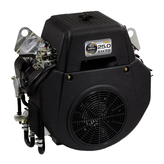
- Page 1 SERVICE INFORMATION...
-
Page 3: Table Of Contents
PREFACE This manual covers the service information, trouble shooting procedures and so on of EH72 FI (Fuel injection) engine . Careful observance of the instructions given herein will result in better, safer and faster service work . For more detailed instructions of disassembling and reassembling procedures, please refer to the service manual for EH63, 64, 65 and 72 . -
Page 4: Specifications
1. SPECIFICATIONS Model EH72 FI Air-Cooled, 4-Stroke, V-Twin Cylinder, Horizontal P .T .O . shaft, Type OHV Gasoline Engine 2 - 84 × 65 (3 .31 × 2 .56) Number of Cylinders - Bore×Stroke mm (in.) Displacement ml (cu.in.) 720 (43 .9) Compression Ratio 8 .1... -
Page 5: Features
2. FEATURES EH72 FI has been developed as a high performance model equipped with the electronic fuel injection system . HIGHER POWER OUTPUT has been achieved by increasing inlet air volume with larger venturi bore . ENVIRONMENTALLY FRIENDLY By optimizing the fuel injection management, EH72 FI has achieved approx . 11% improvement on the fuel efficiency, as well as drastic reduction on the exhaust emission . -
Page 6: Description Of Fuel System
3. DESCRIPTION OF FUEL SYSTEM This engine is equipped with Electronic Fuel FUEL PRESSURE Injection system (FI system) integrated with REGULATOR THROTTLE ECU (Engine Control Unit) . BODY AY The FI system consists of throttle body (2-barrel), ECU, MAP (Manifold Air Pressure) sensor, injector, fuel pressure regulator, temperature sensor, electric fuel pump, and INJECTOR... -
Page 7: Disassembly And Reassembly
4. DISASSEMBLY AND REASSEMBLY 4-1 PREPARATIONS AND SUGGESTIONS When disassembling the engine, memorize the locations of individual parts so that they can be reassembled correctly . If you are uncertain of identifying some parts, it is suggested that tags be attached to them . -
Page 8: Disassembly Procedures (Difference)
4-3 DISASSEMBLY PROCEDURES (DIFFERENCE) Step Parts to remove Remarks and procedures Parts Fasteners Choke lever Choke lever not applicable . Governor rod (1) Remove the governor rod spring from rod holder . (2) Pick up the rod holder and remove the governor rod . (See Fig .4-1) (3) Remove the governor rod and the rod spring from the governor lever . - Page 9 Step Parts to remove Remarks and procedures Parts Fasteners Throttle body (1) Disconnect the two connectors from ECU under the throttle body . (2) Disconnect the two connectors from the two injectors on the throttle body . (3) Remove the nuts, adapter and throttle body from the M6 Flange nut : 4pcs .
- Page 10 Step Parts to remove Remarks and procedures Parts Fasteners Fuel pump (1) Disconnect the connecter places from fuel pump wiring harness 2 . M6 x 12 Flange bolt : 1 pc . (2) Remove fuel pump ASSY and detach bracket . PLUG IGNITION TERMINAL...
- Page 11 Step Parts to remove Remarks and procedures Parts Fasteners Regulator and Wire CP (1) Disconnect wire connector from regulator, and then M6 x 12 Flange bolt : 2 pcs . remove regulator from #1 cylinder baffle . (2) Remove temperature sensor from main bearing cover . Tapping screw : 1pc .
-
Page 12: Reassembly Procedures (Difference)
4-4 REASSEMBLY PROCEDURES (DIFFERENCE) 20) COOLING FAN Attach cooling fan onto flywheel . M6 x 16 bolt & washer : 4 pcs . Tightening torque 6.8 - 8.8 N•m (70 - 90 kgf•cm) (5.1 - 6.5 ft•lb.) 21) THROTTLE BODY (1) Replace the gasket of manifold with a new INTAKE one and mount the throttle body on the... - Page 13 . (3) Connect governor spring to governor lever FRICTION M6 FLANGE WASHER and speed control lever . BOLT BRACKET UNIT, speed control Fitting location of governor rod and governor spring 50 Hz 60 Hz EH72 FI A-2(a) - 10 -...
- Page 14 25) ADJUST GOVERNOR SYSTEM ● Governor system is centrifugal flyweight type . Governor weight is installed into governor gear driven by crankshaft . Governor weight movement is transferred to throttle lever via governor shaft and lever . GOVERNOR LEVER GOVERNOR SHAFT ●...
- Page 15 27) FUEL PUMP and FUEL PIPE (1) Install fuel pump bracket onto #2 cylinder baffle . FUEL PUMP RETURN HOSE M6 x 12 Flange bolt : 1 pc . FUEL PUMP Tightening torque 6.8 - 8.8 N•m FUEL FILTER (70 - 90 kgf•cm) (5.0 - 6.5 ft•lb.) CONNECTER PULSATION DAMPER...
- Page 16 30) OIL FILTER Apply oil to O-ring and install oil filter by tightening about 3/4 turns after attaching crankcase surface . Tightening torque 9.9 - 14.7 N•m (100 - 150 kgf•cm) OIL FILTER (16.3 - 19.8 ft•lb.) 3/4 TURNS NOTE ; Start engine after assembling, and check for no oil leakage from oil filter.
-
Page 17: Break-In Operation
. While the engine is being tested, check for oil leaks . Make final carburetor adjustment and regulate the engine operating speed . STEP EH72 FI Engine speed (rpm) Time (minute) 2500... -
Page 18: Diagram
5. DIAGRAM WIRING Blk : BLACK : WHITE OIL/FAIL WARNING LAMP : RED (OPTION) ELECTRIC : YELLOW FUEL PUMP Grn : GREEN Gry : GRAY Grn, R (Covering: Blk) THROTTLE BODY PRESSURE CLEANER SWITCH #2 CYLINDER SIDE (Wiring harness 2) ADAPTER Blk / W Blk (Covering: Gry) -
Page 19: Throttle Body
6. THROTTLE BODY 6-1 SPECIFICATIONS This engine is equipped with Electronic Fuel Injection system (FI system) integrated with ECU (Engine Control Unit) . The FI system consists of throttle body (2-barrel), ECU, MAP (Manifold Air Pressure) sensor, injector, pressure regulator, temperature sensor, electric fuel pump, and pulsation damper . The fuel system is calibrated after careful testing for optimum all-round performance (including starting, acceleration, fuel consumption, output power characteristics) . -
Page 20: Fuel System Outline
6-2-4 WIRE HARNESS The wire harness for the FI system connects key system components to the ECU . The FI wire harness contains a temperature sensor that measures engine temperature, and connects fuel injectors, ignition coils, electric fuel pump, pressure switch, and warning lamp . The ECU uses this input to adjust to engine various conditions and monitors for failure diagnosis . -
Page 21: Installation
7. INSTALLATION Engine life, ease of maintenance and inspection, frequency of checks and repairs, and operating cost all depend on the way in which the engine is installed . Review the following instructions carefully for installing the engine . 7-1 INSTALLING When mounting the engine, carefully examine its position, the method of connecting it to a machine, the foundation, and the method of supporting the engine . -
Page 22: Fuel System
7-4 FUEL SYSTEM When the fuel tank is mounted remote position from the engine, the height from the bottom of the fuel tank to the fuel joint of the throttle body should be 500 mm and less . The bottom of the fuel tank can be up to 400 mm below the throttle body . Position the fuel tank carefully because, when it is low, fuel is not fed to the throttle body, and when it is high, it can cause high pressure in the throttle body then fuel rich and high fuel consumption . -
Page 23: Troubleshooting
8. TROUBLESHOOTING The following three conditions must be fulfilled for satisfactory engine start . (1) The cylinder filled with a proper fuel-air mixture . (2) Good compression in the cylinder . (3) Good spark, properly timed, to ignite the mixture . The engine cannot be started unless these three conditions are met . -
Page 24: Starting Difficulties
8-2 STARTING DIFFICULTIES Phenomenon Possible causes Remedy 1) Battery discharged Charge battery 2) Poor connection between battery and starter motor Clean or repair 1 . Low engine 3) Poor connection between battery and ground Clean or repair speed at starting 4) Electric starter faulty Repair or replace Replace with recommended... -
Page 25: Insufficient Output
8-3 INSUFFICIENT OUTPUT Phenomenon Possible causes Remedy 1) Loosen spark plug Retighten or replace gasket 2) Cylinder head gasket leakage Retighten or replace gasket 3) Piston ring(s) seizure or wear Replace 1 . Low 4) Piston or cylinder wear Repair or replace compression 5) Incorrect valve and seat contact Repair or replace... -
Page 26: Rough Idling
8-5 ROUGH IDLING Phenomenon Possible causes Remedy 1) Low idling speed Adjust 1 . Throttle body 2) Throttle body slow system passage clogged Check, clean and replace 2 . Intake system 1) Air mixing from connecting portion of air intake system Check, tighten or replace gasket 3 . -
Page 27: High Fuel Consumption
8-7 HIGH FUEL CONSUMPTION Phenomenon Possible causes Remedy 1) Throttle body faulty Check or replace 1 . Fuel system 2) Pulsation damper faulty Check or replace 3) Fuel pump faulty Check or replace 1) Low compression Check or repair 2 . Engine core components Check and adjust load and/or 2) Over cooling... -
Page 28: Engine Misfire
8-9 ENGINE MISFIRE Phenomenon Possible causes Remedy 1) Improper spark plug gap or damaged electrode Cealn, adjust or replace 2) Ignition coil faulty Replace 1 . Ignition system Check with failure diagnosis 3) Damaged ignition system wirings system and replace Check with failure diagnosis 4) Poor connection of ignition system wirings system and connect properly... -
Page 29: Diagnosis Code
8-10 DIAGNOSIS CODE This engine has the failure diagnosis system to know that low voltage of DC battery and each wiring whether disconnecting or electrical short circuit . The ECU monitors engine various conditions for the system when tune the key to the “RUN” (ON) position, “START” (cranking) or after start the engine . - Page 30 Step Key position Description In case of another failure, after the 4 sec the lamp repeats turning on and off . This sample is failure code means “4-2” . Fore (4) turning on and off, and go out 2 sec then turning START on 0 .4 sec .
-
Page 31: Maintenance And Storage
9. MAINTENANCE AND STORAGE 9-1 DAILY MAINTENANCE Every day before operating engine, check the following items : MAINTENANCE ITEMS REMARKS 1) Clean away dust and chaff from engine . Governor linkage is especially sensetive to dust . 2) Check fuel leakage from fuel system . If any, retighten fasteners or replace necessary parts . - Page 32 Periodic Maintenance Schedule table Every Every Every Every Every 1000 8 hours 50 hours 200 hours Maintenance Items hours (Daily) (Weekly) (Monthly) hours Clean engine and check bolts and nuts (Daily) Check and refill engine oil (Refill daily up to upper level) Change engine oil (*Note : 1) (Initial 20 hours) (Every 100 hours)
-
Page 33: Spark Arrester (Optional)
9-3 SPARK ARRESTER (OPTIONAL) In a dry or wooded area, it is recommendable to use the product with a spark arrester . Some areas require the use of a spark arrester . Please check your local laws and regulations before operating your product . -
Page 34: Engine Storage
9-4 ENGINE STORAGE (1) Drain fuel from fuel tank and run the engine until there is no fuel left . (2) Change the engine oil and perform the daily maintenance items above mentioned . (3) To prevent rust in the cylinder bore, apply oil through the spark plug hole and turn the crankshaft several turns by hand . - Page 36 ISSUE EMD-ES6790...
Need help?
Do you have a question about the EH72 FI and is the answer not in the manual?
Questions and answers