Advertisement
Quick Links
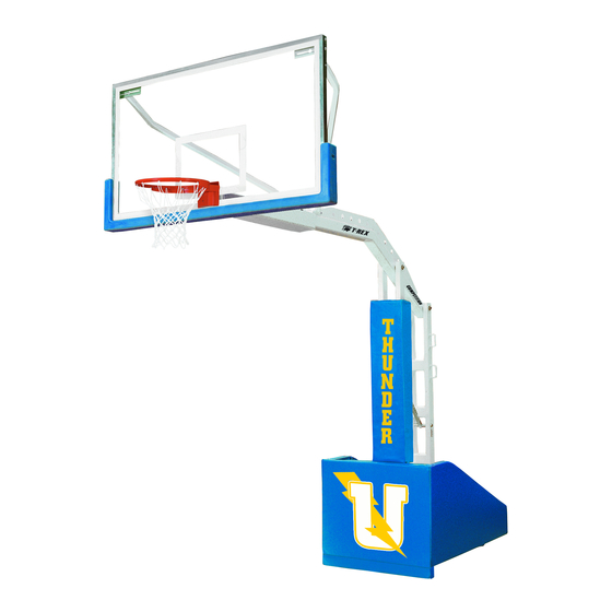
Portable Adjustable Basketball Systems
P A R T S L I S T
Item
Qty
Description
A
1
Portable Base
B
2
Leveling Pad
C
2
Square Nut
D
4
1/2" Flat Washer
E
2
Backboard Brace
F
4
3/8" X 1" Hex Bolt
G
2
3/8" Flat Washer
H
2
3/8" Lock Washer
I
2
3/8" Hex Nut
J
1
Backboard (pkg. separately)
K
2
Rod End
L
1
Breakaway Goal (pkg. separately)
Do not remove the safety strap until the backboard and goal installation is complete.
This unit is under extreme spring tension and severe injury and damage will result.
Inspect all contents prior to installation. Report any missing parts immediately.
Carefully read all instructions before proceeding. Pay special attention to all safety instructions.
Save this instruction in the event that the manufacturer must be contacted in the future for maintenance
information.
1. Carefully lift the front of the unit with a forklift or 4 adults until the factory installed back wheels make
contact. Remove and discard the shipping pallet. Using the Square Nuts (C) with the radiused corners
facing down, install the Front Leveling Pads (B) onto the Portable Base (A) and tighten the bottom jam
nuts against the bottom of the Portable Base (A). See Figure 1 and 2.
2. Using 3/8" X 1" Hex Bolts (F) install the Backboard (J) to the extension arm. Install the Breakaway
Goal (L) using the 3/8" X 1" Hex Bolts (F) in the bottom holes and the 3/8"X 4 1/2" Hex Bolts (S),
3/8" Flat Washers (G), 3/8" Lock Washers (H) and 3/8" Hex Nuts (I) going through the top Breakaway
Goal (L) holes, the top Backboard (J) holes and the top holes in the base extension arm. Leave hardware
loose or finger tight for leveling backboard from side to side, later in the instructions. See Figure 3.
3. Remove the safety strap.
4. There are 3 finger like tabs to chose from when raising and lowering the portable base wheel assembly for
transportation. Finger #1 is used when there is a significant floor threshold you need to pass over and shall
be used only if necessary. Finger #2 is for normal transport and finger #3 is for low door heights, but may
not raise the base adequately to provide easy movement. See Figure 4
Date: 04/13/2020
Rev: 13
—— Instruction Manual ——
Warning!
B.A.
N.J.C.
Item
Qty
Description
M
4
1/2" Lock Nut
N
1 set
Pads (front, side, and beam (if applicable))
(pkg. separately)
O
20
1/4" X 3/4" Flat Head Screw
P
2
Front Locator Pin
Q
8
Padding Bracket (White)
R
2
Floor Bushing
S
2
3/8" X 4 1/2" Hex Bolt
T
2
Padding Bracket (Gray)
U
2
1/2" X 2 1/2" Hex Bolt
V
1
Lock
W
1
Removeable Handle
X
1
Rear Hold Down Kit (Optional on some models)
File: 895G/ 898Generic
1
Ref#:930354
Advertisement

Related Manuals for Bison T-REX BA898G-BK


Summary of Contents for Bison T-REX BA898G-BK
- Page 1 —— Instruction Manual —— Portable Adjustable Basketball Systems P A R T S L I S T Item Description Item Description Portable Base 1/2” Lock Nut Leveling Pad 1 set Pads (front, side, and beam (if applicable)) (pkg. separately) Square Nut 1/4”...
- Page 2 Figure 3 Figure 1 Figure 2 5. Sliding the Removeable Handle (W) over Finger #2, push down and outward to secure the unit under the handle catch for the transport position. Adjust the Leveling Pads (B) until the Portable Base (A) extension arm is level front to back and the base is level side to side when the Portable Base (A) is lowered back onto the Leveling Pads (B).
- Page 3 Measure the Breakaway Goal (L) height and if necessary readjust the two Leveler Pads (B) equally to achieve the official 10’ playing height. Check to make sure the Backboard (J) and the Breakaway Goal (L) are still level. Once the Backboard (J) and Breakaway Goal (L) are level and the Breakaway Goal (L) is at the 10’...
- Page 4 14. If you intend to use the Front Locator Pins (P) for easy repositioning, move Portable Base (A) to the desired location for play. Warning! While the Portable Base (A) can be moved when the Backboard (J) is raised to the play position, it is advisable to only raise the goal when unit is at or near its intended play location to avoid difficulty in handling.
-
Page 5: Safety Warning
Figure 15 SAFETY WARNING: DO NOT hang on the rim or any part of system including backboard, support braces, or net. DO NOT slide, climb, or play on system. When adjusting height, keep hands and fingers away from moving parts. DO NOT allow young children to adjust or move system.