NuTone Performance CV350 Installation Instructions Manual
Built-in central cleaning system
Hide thumbs
Also See for Performance CV350:
- Specifications (1 page) ,
- Homeowner's operating instructions (6 pages) ,
- Operating instructions manual (6 pages)
Table of Contents
Advertisement
Built-In Central Cleaning System
MODEL: CV350, CV353, CV450, CV553
Examples . . . . . . . . . . . . . . . . . . . . . . . . . . . . . . . . . . . . . . . . . . . .2
Locating the Power Unit . . . . . . . . . . . . . . . . . . . . . . . . . . . . . . . . .3
Tubing and Wall Inlet Location . . . . . . . . . . . . . . . . . . . . . . . . . . .3
Locating Access Keys in Existing Construction . . . . . . . . . . . . . . .3
INSTALLATION IN NEW CONSTRUCTION . . . . . . . . . . . . . . . .4-8
Wall Inlet Rough-In . . . . . . . . . . . . . . . . . . . . . . . . . . . . . . . . . . . .4
Installing the Tubing . . . . . . . . . . . . . . . . . . . . . . . . . . . . . . . . . . . .5
Model 360 Wall Inlets . . . . . . . . . . . . . . . . . . . . . . . . . . . . . . . .6
Model 330 Wall Inlet . . . . . . . . . . . . . . . . . . . . . . . . . . . . . . . . .6
Model CI390 Wall Inlet (Electrified Inlet) . . . . . . . . . . . . . . . . . .7
POWER UNIT INSTALLATION . . . . . . . . . . . . . . . . . . . . . . . . . . .8
Dimensional Chart . . . . . . . . . . . . . . . . . . . . . . . . . . . . . . . . . . . .8
Mounting . . . . . . . . . . . . . . . . . . . . . . . . . . . . . . . . . . . . . . . . . . .8
Tubing Connections at Power Unit . . . . . . . . . . . . . . . . . . . . . . .8
Wiring . . . . . . . . . . . . . . . . . . . . . . . . . . . . . . . . . . . . . . . . . . . . . .8
INSTALLATION IN EXISTING CONSTRUCTION . . . . . . . . . . .9-10
Model 360 Wall Inlets . . . . . . . . . . . . . . . . . . . . . . . . . . . . . . . .9
Model 330 Wall Inlet . . . . . . . . . . . . . . . . . . . . . . . . . . . . . . . .10
FLOOR INLET INSTALLATION . . . . . . . . . . . . . . . . . . . . . . .10-11
FINAL SYSTEM CHECK . . . . . . . . . . . . . . . . . . . . . . . . . . . . . . . .11
WARRANTY . . . . . . . . . . . . . . . . . . . . . . . . . . . . . . . . . . . . . . . . .12
. . . . . . . . . . . . . . . . . . . . . .2
INSTALLATION
INSTRUCTIONS
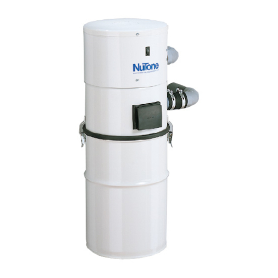
MODEL CV450 SHOWN
Advertisement
Table of Contents

Related Manuals for NuTone Performance CV350


Summary of Contents for NuTone Performance CV350
-
Page 1: Table Of Contents
Built-In Central Cleaning System MODEL: CV350, CV353, CV450, CV553 SYSTEM PLANNING AND LAYOUT Examples ..........2 Locating the Power Unit . -
Page 2: System Planning And Layout
SYSTEM PLANNING AND LAYOUT The NuTone Central Cleaning System consists of a Power Unit, PVC Tubing and Fittings, Wall Inlets, a flexible Hose and various cleaning Attachments. The Power Unit is designed to be wall-mounted away from the living area of the home and connected to the living area by means of permanently installed in-wall tubing, fittings and inlets. -
Page 3: Locating The Power Unit
LOCATING THE POWER UNIT • Locate the power unit away from the general living area in an accessible location for changing the soil bag and periodically cleaning the secondary filter. • When planning, remember the power unit is equipped with an inlet to service a garage, basement, utility room, etc., wherever it is located. -
Page 4: Installation In New Construction
INSTALLATION IN NEW CONSTRUCTION WALL INLET ROUGH-IN Once the locations for wall inlets have been determined, mount all inlet brackets. 1. Choose the appropriate mounting bracket for the inlet being installed. (See chart.) NuT one Inlet 330 Series 360 Series CI390 Series Electrified Inlet 2. -
Page 5: Installing The Tubing
INSTALLATION IN NEW CONSTRUCTION INSTALLING THE TUBING Use the following installation guidelines when installing tubing. Start tubing installation at farthest inlet and work toward the power unit. Tubing run to the power unit should be as straight as possible. When assembling sections with elbows and tees, make sure the curve in the fitting is aligned so that the air flows toward the power unit. -
Page 6: Wall Inlet Installation
INSTALLATION IN NEW CONSTRUCTION WALL INLET INSTALLATION MODEL 360 WALL INLET (361 Rough-In) 1. Remove the cardboard plaster guard. 2. Refer to Figure 17. For some drywall or panel construction, the plaster frame will extend beyond the finished wall. In this case, remove plaster frame from mounting bracket by removing mounting screws. -
Page 7: Model Ci390 Wall Inlet (Electrified Inlet)
INSTALLATION IN NEW CONSTRUCTION CI-390 ELECTRAVALVE™ ELECTRIFIED INLET INSTALLATION (CI-390RK Rough-In) (Not available in Canada) 1. See Figure 23. Fasten the mounting plate to a stud within three studs (48") of an electrical outlet box. Measure and mark the wire 10" from the plug (A). Feed the wire through the top hole in the mounting plate (just above the circular opening). -
Page 8: Power Unit Installation
POWER UNIT INSTALLATION MINIMUM WALL CLEARANCE DIMENSIONS 12" 18" “D” INTAKE TOP VIEW 12" MINIMUM TO CEILING FRONT VIEW “B” TOP OF UNIT TO KEYHOLE SLOT EXHAUST “A” OVERALL HEIGHT INTAKE 18" MINIMUM ABOVE FLOOR DIMENSIONAL CHART MODELS DIMENSION CV350 CV353 CV450 ⁄... -
Page 9: Installation In Existing Construction
INSTALLATION IN EXISTING CONSTRUCTION Use the following procedures for installation in existing construction. Starting from farthest wall inlet location, install each inlet as described below. Working back toward power unit, connect each inlet line and branch line into main trunk line. See page 5. Complete low voltage wiring as main trunk line is continued back to power unit. -
Page 10: Floor Inlet Installation
INSTALLATION IN EXISTING CONSTRUCTION MODEL 330N WALL INLET INSTALLATION (329 Rough-in) 1. Make cutout according to dimensions in Figure 34. 2. Refer to Figure 35. Break off nail plate at scored line. 3. Refer to Figure 36. Glue elbow to mounting plate, place assembly into cutout, and attach elbow to tubing inside the wall. -
Page 11: Floor Inlet Installation
FLOOR INLET INSTALLATION FLOOR INLET INLET EXTENSION " FLOOR SUB-FLOOR MOUNTING BRACKET FIGURE 40 FINAL SYSTEM CHECK Be sure all inlets are closed and soil bag is in place. Check switch on power unit for manual on/off operation. Check each wall inlet to be sure contacts activate power unit when hose is inserted and switched on, if applicable. -
Page 12: Warranty
Residents of Alaska or Hawaii should write to: NuTone Inc. Attn: Department of National Field Service, 4820 Red Bank Road, Cincinnati Ohio 45227-1599. Residents of Canada should write to: Broan-NuTone Canada, 1140 Tristar Drive, Mississauga, Ontario, Canada L5T 1H9. ®...
Need help?
Do you have a question about the Performance CV350 and is the answer not in the manual?
Questions and answers
Can the CV-353 be run without venting via muffler or is it a closed system
The NuTone CV350 is not a closed system and cannot be run without proper venting. The exhaust should not be vented into a wall, ceiling, or concealed space in the house. It must be vented to the exterior using mufflers and appropriate exhaust vents such as Model 393 Wall Caps or louvered exhaust vents.
This answer is automatically generated