Table of Contents
Advertisement
Quick Links
Advertisement
Table of Contents

Related Manuals for Megger 128311841


Summary of Contents for Megger 128311841
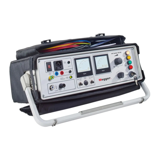
- Page 1 Operating Manual HV Tester 25 kV 128311841...
- Page 3 Megger have before-hand declared their consent in writing. The content of this handbook is subject to change without notice. Megger cannot be made liable for technical or printing errors or shortcomings of this handbook. Megger also disclaim all responsibility for damage...
- Page 4 Each component and product replaced in accordance with this warranty becomes the property of Megger. All warranty claims versus Megger are hereby limited to a period of 12 months from the date of delivery. Each component supplied by Megger within the context of warranty will also be covered by this warranty for the remaining period of time but for 90 days at least.
-
Page 5: Table Of Contents
Operating Manual HV Tester 25 kV Table of content GENERAL Safety instructions INDICATIONS USED IN THE DESCRIPTION TECHNICAL DESCRIPTION Description of the set 2.1.1 Scope of supply 2.1.2 Use of the set Design of the set Function Specifications PREPARATION FOR USE Operating requirements Power supply 3.2.1... - Page 6 Operating Manual HV Tester 25 kV Table of Figures: Figure 1 HV Tester 25 kV Figure 2 HV Tester 25 kV Figure 3 Example for connecting HV Tester 25 kV Figure 4 Front of the HV Tester 25 kV...
-
Page 7: General
Operating Manual HV Tester 25 kV GENERAL The HV Tester is a generator of high direct voltages. The insulation of cables, electrical plant and plant components can be tested for electric strength with this set. The insulation resistance of test objects can be determined by measuring current and voltage using integrated measuring instruments. -
Page 8: Indications Used In The Description
Operating Manual HV Tester 25 kV ELECTROTECHNICAL INSTRUCTIONS The system and all additional equipment must be connected properly. The relevant DIN and VDE regulations must be complied with. Maintenance work must only be carried out when the system is switched off (dead) and then only by qualified and/or trained staff. INDICATIONS USED IN THE DESCRIPTION Important instructions concerning personal protection, work safety and technical safety are indicated as follows:... -
Page 9: Technical Description
Operating Manual HV Tester 25 kV TECHNICAL DESCRIPTION Description of the set 2.1.1 Scope of supply The scope of supply includes the following: Item Description 00001 HV Tester 25 kV with built in batteries and softcase 00002 Mains connecting cable 00003 Connecting cable for external battery... -
Page 10: Design Of The Set
Operating Manual HV Tester 25 kV Design of the set The compact HV Tester 25 kV is very portable thanks to its small size and low weight and can be used directly on-site. State-of-the-art technique and clearly designed operation panel for easy application. The control and display elements as well as the high-voltage outlet are arranged on the control panel. -
Page 11: Specifications
Operating Manual HV Tester 25 kV Specifications Power supply mains 115 or 230 V AC built-in rechargeable batteries external DC voltage 11-15 V Power consumption 120 W max DC output voltage 0...25 kV (negative polarity, infinitely variable) Output current 1.5 mA 1.6 mA ±... - Page 12 Operating Manual HV Tester 25 kV...
-
Page 13: Preparation For Use
Operating Manual HV Tester 25 kV PREPARATION FOR USE Operating requirements The carrying handle of HV Tester 25 kV can be adjusted by exerting gentle sideways pressure on the buttons on either side in the joint area. WARNING: The clearance between the high-voltage unit and grounded or live parts as stipulated in DIN VDE 0104 must be complied with. -
Page 14: Mains
Operating Manual HV Tester 25 kV 3.2.2 Mains If the set is connected to the mains, the external DC voltage and internal battery are switched off (signalled by the green LED [11] p. 11). Mains operation is accompanied by recharging / floating operation of the internal battery. -
Page 15: Connecting The Test Equipment
Operating Manual HV Tester 25 kV Connecting the test equipment The connecting cable is in the front of the carrying case. Voltage selector Power supply Fuse (1.25 A slow for 115 V and 230 V) Connector for external battery Station ground HV connector Protective conductor terminal Figure 2... - Page 16 Operating Manual HV Tester 25 kV Before the test equipment is connected, safe isolation from supply must be established and safeguarded in accordance with DIN VDE 0105. The requirements of DIN VDE 0104 and DIN VDE 0105 must be complied with. The test equipment should be connected in the following order: Ground and short-circuit the conductor of the test object that is not going to be tested (connect to station ground or auxiliary ground...
-
Page 17: Operating Instructions
Operating Manual HV Tester 25 kV OPERATING INSTRUCTIONS Controls and displays The controls and displays needed to operate the HV Tester are on the front of the operation unit. 13 12 11 Figure 4 Front of the HV Tester 25 kV The following tables explain the controls: Item Description... -
Page 18: Operating Procedure
Operating Manual HV Tester 25 kV OPERATING PROCEDURE 4.2.1 Performing measurements When the mains key switch is turned on, the white pilot lamp (Figure 4 p. 11 [4]) lights up. If the equipment is grounded properly, the yellow pilot lamp also lights up. If this does not happen, the HV Tester still has to be grounded (protective conductor terminal). -
Page 19: Ending Testing
Operating Manual HV Tester 25 kV 4.2.2 Ending testing Once testing is complete, turn the voltage down and switch the equipment off ("HV off" Figure 4 p. 11 [7]). When the test time expires, the high voltage is switched off automatically by the timer and the discharge device is activated. - Page 20 Operating Manual HV Tester 25 kV...
-
Page 21: Care, Maintenance And Repair
Operating Manual HV Tester 25 kV CARE, MAINTENANCE AND REPAIR The repair work, which can be done on the HV Tester by the user is limited to the replacement of fuses and lamps. Fuses, lamps and tools are included in the service kit. The HV Tester 25 kV is test equipment and as such must be handled and looked after with care. - Page 22 Operating Manual HV Tester 25 kV...
- Page 23 Tento symbol indikuje, že výrobek nesoucí takovéto označení nelze likvidovat společně s běžným domovním odpadem. Jelikož se jedná o produkt obchodovaný mezi podnikatelskými subjekty (B2B), nelze jej likvidovat ani ve veřejných sběrných dvorech. Pokud se potřebujete tohoto výrobku zbavit, obraťte se na organizaci specializující se na likvidaci starých elektrických spotřebičů...
Need help?
Do you have a question about the 128311841 and is the answer not in the manual?
Questions and answers