Advertisement
Available languages
Available languages
Quick Links
DE FR ES IT EN
Einbau- und Bedienungsanleitung
Kompakt-Wärmezähler
Kompakt-Wärme- / Kältezähler
Kompakt-Kältezähler
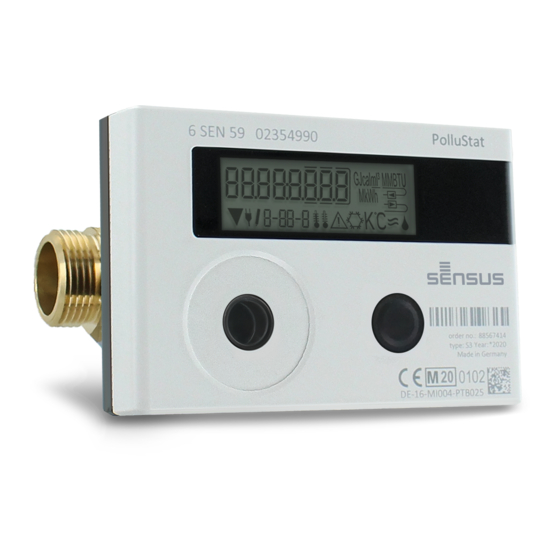
PolluStat
Ultraschallzähler
DE-16-MI004-PTB025 (MID Wärme)
DE-16-M-PTB-0097 (nationale Zulassung für Kälte in Deutschland)
CH-T2-18768-00 (nationale Zulassung für Kälte in der Schweiz) OE18
C340 (nationale Zulassung für Kälte in Österreich)
1 Verwendung und Funktion
Der PolluStat dient zur Erfassung der Verbrauchsmenge in geschlossenen Heizsystemen, Kühlsystemen oder Heiz- /
Kühlsystemen.
2 Lieferumfang
-
Wärmezähler, bestehend aus miteinander untrennbar verbundenem Rechenwerk, Durchflusssensor und zwei
Temperatursensoren
-
Beipack Montage (je nach Ausführung des Durchflusssensors)
-
Beipack Kennzeichnungsschild Tauchhülse
-
Einbau- und Bedienungsanleitung inkl.:
°
Bedienungsanleitung „Kommunikationsschnittstellen PolluStat" (bei Zählern mit optionaler Schnittstelle)
°
Dokument zur „Tauchhülsenduldung"
°
Konformitätserklärung
3 Allgemeine Hinweise
-
Geltende Norm für den Einsatz von Wärmezählern: EN 1434, Teile 1 - 6. Richtlinie 2014/32/EU, Anhang I und MI-004
und die jeweilige relevante Eichordnung des Landes, in dem der Zähler eingesetzt wird.
-
Für Auswahl, Einbau, Inbetriebnahme, Überwachung und Wartung des Gerätes sind EN 1434 Teil 6 sowie die PTB TR K
8 und TR K 9 zu beachten.
-
Nationale Regelungen zur Verbrauchsmessung von Kältemengen sind zu beachten.
-
Bei Geräten für kombinierte Wärme- / Kältemessung ist das Kälteregister nicht geeicht und darf daher nicht für
Abrechnungszwecke im geschäftlichen Verkehr herangezogen werden.
-
Die Vorschriften für Elektroinstallationen sind zu beachten.
-
Das Produkt erfüllt die wesentlichen Anforderungen, die in der EU-Richtlinie über die elektromagnetische
Verträglichkeit (EMV-Richtlinie) für Betriebsmittel (2014/30/EU) festgelegt sind.
-
Eichrelevante Sicherungszeichen des Zählers dürfen nicht beschädigt oder entfernt werden - andernfalls entfallen
Garantie und Eichfrist des Gerätes!
-
Die Messbeständigkeit der Zähler ist nur gegeben, wenn die Wasserqualität den Bedingungen der AGFW-Empfehlung
FW-510 und der VDI 2035 entspricht.
-
Der Zähler hat das Werk in einwandfreiem Zustand verlassen. Sämtliche Installationsarbeiten dürfen nur von einer
hierfür ausgebildeten und befugten Fachkraft ausgeführt werden.
-
Geräte mit aktiviertem Funk dürfen nicht in die Luftfracht.
-
Der Einbauort (Vorlauf / Rücklauf) des Zählers ist zu beachten (siehe Punkt 3.1: Piktogramme Einbauort).
-
Die Temperatursensor- und Splittkabel nicht knicken, aufwickeln, verlängern oder kürzen.
-
Zur Reinigung ein mit Wasser befeuchtetes Tuch verwenden.
-
Zum Schutz vor Beschädigung und Verschmutzung ist der Zähler erst unmittelbar vor dem Einbau aus der Verpackung
zu nehmen.
-
Werden mehrere Zähler in einer Einheit eingebaut, sollte darauf geachtet werden, dass bei allen Zählern möglichst die
gleichen Einbaubedingungen vorliegen.
-
Alle Hinweise, die im Datenblatt, der Bedienungsanleitung und Application notes des Zählers aufgeführt sind, müssen
beachtet werden. Weitere Informationen unter www.sensus.com | www.xylem.com.
Page 1 of 108
Article no.: 1080619046
2020_07_27
Subject to technical change! Errors excepted.
DE
Advertisement

Related Manuals for Xylem PolluStat


Summary of Contents for Xylem PolluStat
- Page 1 CH-T2-18768-00 (nationale Zulassung für Kälte in der Schweiz) OE18 C340 (nationale Zulassung für Kälte in Österreich) 1 Verwendung und Funktion Der PolluStat dient zur Erfassung der Verbrauchsmenge in geschlossenen Heizsystemen, Kühlsystemen oder Heiz- / Kühlsystemen. 2 Lieferumfang Wärmezähler, bestehend aus miteinander untrennbar verbundenem Rechenwerk, Durchflusssensor und zwei Temperatursensoren Beipack Montage (je nach Ausführung des Durchflusssensors)
- Page 2 3.2 Piktogramme Zählerausführung (auf dem Typenschild) Wärmezähler Kältezähler 4 Montage des Durchflusssensors 4.1 Montage des PolluStat Rohrleitung gemäß den anerkannten Regeln der Technik spülen. Alle Absperrorgane schließen. Nahe gelegenes Entleerungsventil am Absperrhahn zur Druckentlastung öffnen. Abgesperrte Rohrstrecken entleeren. Überwurfmuttern am alten Wärmezähler bzw. Passstück lösen.
- Page 3 Bedeutung. Es wird empfohlen, das Rechenwerk des Wärmezählers vom Durchflusssensor abzunehmen. Bei Kältezählern und Wärme- / Kältezählern muss das Rechenwerk vom Zähler abgenommen werden. PolluStat Bei der Ausführung Wärme für Hochtemperatur des (Medium-Temperatur bis 130 °C) und bei der Ausführung PolluStat Wärme / Kälte für Hochtemperatur des...
- Page 4 6.3 Direkteinbau Temperatursensoren 6 mm Wichtiger Hinweis: Absperrventile schließen und sicherstellen, dass bei der Entfernung des Blindstopfens bzw. des alten Fühlers kein (heißes) Wasser herausspritzen kann! Fühler vorbereiten (Vor- u. Rücklauf): O-Ring jeweils in erste Sicke positionieren (von Fühlerspitze aus). Fühler in die Messstelle am EAT und am Kugelhahn oder T-Stück einführen und mit Hilfe der MessingÜberwurfmuttern befestigen.
- Page 5 Ebene 1 / Hauptschleife: 2) Segmenttest an / aus (alle 4) Kumuliertes Volumen in Anzeigefelder werden m³ gleichzeitig angesteuert) 1) Kumulierte Wärmemenge seit Inbetriebnahme (Standarddisplay); 3) Letzter Stichtag im Wechselanzeige: Wechsel mit kumulierte Kältemenge (für Wärmemenge Wärme-/Kältezähler); bei (Kältemenge), negativem Fluss; Volumen, Hinweiscode (falls ein Fehler Wert Tarifregister 1,...
- Page 6 Ebene 2 / Technikschleife: 2) Aktueller Durchfluss in 3) Vorlauftemperatur in °C 4) Rücklauftemperatur in °C 1) Aktuelle Leistung in kW m³/h. (Bei Rückfluss wird Wert negativ dargestellt.) 7) M-Bus Adresse 5) Temperaturdifferenz in K. 6) Vor Inbetriebnahme: 8) Seriennummer (Bei Kältezählung wird Wert negativ dargestellt.) Betriebstage seit Fertigung...
- Page 7 Ebene 4 / Maximalwertschleife: 3) Maximale Vorlauf- 1) Maximale Leistung im 4) Maximale Rücklauf- 2) Maximaler Durchfluss Temperatur Wechsel mit Datum und Temperatur im Wechsel im Wechsel mit Datum und im Wechsel mit Datum und mit Datum und Uhrzeit Uhrzeit Uhrzeit Uhrzeit 5) Maximale Temperatur-...
- Page 8 8.2 Durchflusserkennung Solange der Zähler einen Durchfluss erkennt, wird rechts unten im Display das folgende Piktogramm angezeigt. Durchfluss erkannt Einsatzbedingungen PolluStat Maximaldurchfluss qs/qp Mechanische Klasse Elektromagnetische Klasse Umgebungsklasse Schutzklasse DFS IP65 Nenndruck PN Einbaulage beliebig, wenn keine Angabe auf dem Typenschild vorhanden ist...
- Page 9 Danach den Schraubendreher in einem Winkel von ca. 45° in eine der beiden Öffnungen einführen und vorsichtig nach oben bewegen bis zu einem Winkel von ca. 90° (Bild 2). Die Oberschale des Rechenwerkes ist nun auf dieser Seite nicht mehr eingerastet.
- Page 10 10.4 Anschluss Netzteil Zur externen Spannungsversorgung muss das für unseren Wärmezähler entwickelte Netzteil verwendet werden. Zum Anschließen des Netzteils öffnen Sie das Rechenwerk des Zählers (Beschreibung siehe Punkt 10.2). Entfernen Sie dann die Batterie aus dem Rechenwerk und schließen Sie sie an die Batteriebuchse im Netzteil an. Netzteil mit einer der beigegebenen nummerierten Klebeplomben gegen Öffnen sichern.
- Page 11 11 Hinweiscodes Wenn das Gerät einen Fehler erkannt hat, wird im Display das Hinweissymbol angezeigt. Der Fehler kann unter dem Menüpunkt 6 „Hinweisanzeige“ in der 1. Ebene / Hauptschleife aufgerufen werden (siehe Kapitel 8: Anzeigemöglichkeiten). Der Hinweiscode wird dort im Wechsel binär und hexadezimal angezeigt. Das Gerät kennt acht mögliche Hinweisursachen, die auch in Kombination auftreten können.
- Page 12 H 02 / H 01 Kurzschluss / Kabelbruch defekt“ _______________________________________________________________________________________________________ Bedienungsanleitung Kommunikationsschnittstellen PolluStat 1 Schnittstellen und Optionen 1.1 Optische (Infrarot-)Schnittstelle Zur Kommunikation mit der optischen Schnittstelle ist ein optischer Auslesekopf nötig. Der Auslesekopf und eine geeignete Konfigurations-Software sind optional erhältlich.
- Page 13 IEC 60364-4-44 (2007-08) Low-voltage electrical installations - Part 4-44: Protection for safety - Protection against voltage disturbances and electromagnetic disturbances IEC 60364-5-51 (2005-04) Electrical installations of buildings - Part 5-51: Selection and erection of electrical equipment - Common rules IEC 60364-5-54 (2011-03) Low-voltage electrical installations - Part 5-54: Selection and erection of electrical equipment - Earthing arrangements and protective conductors EN 50310 (2011)
- Page 14 1.3.2 Funkkonfiguration Parameter Mögliche Einstellungen Werkseinstellung (Betriebsdauer; ausgelegt: 10 Jahre) Modus S1 / T1 / C1; unidirektional T1; unidirektional Sendezeit 00:00 Uhr - 24:00 Uhr 8:00 Uhr - 18:00 Uhr Sendeintervall 10 Sekunden - 240 Minuten 120 Sekunden (Wärmezähler) Wochentage Montag - Sonntag Montag - Freitag Wochen...
- Page 15 1.3.4 Nachträgliche Aktivierung der Funk-Verschlüsselung Die AES-Verschlüsselung kann auch nachträglich aktiviert werden. Dies kann auf zwei Arten geschehen: a) Die Verschlüsselung kann mit dem Taster aktiviert werden. Mit langem Tastendruck bis in die Anzeigenschleife „6“ (Modulschleife) umschalten. Dann mit kurzem Tastendruck zur 3ten Anzeige „AES off“...
- Page 16 1.4.3 Gemeinsame Verwendungsmöglichkeit der Eingangs- (Klasse IB) und Ausgangsvorrichtungen (Klasse OA) Klasse IA Klasse IB Klasse IC Klasse ID Klasse IE Klasse OA Nein Nein Klasse OB Nein Nein Klasse OC Nein Nein Nein Klasse OD Nein Nein Nein Nein Klasse OE Nein Nein...
- Page 17 Wärmeenergie Kälteenergie Wärmeenergie Einstellungen (Werkseinstellung) (Werkseinstellung) (Werkseinstellung) Impulsausgang 1 oder Volumen oder Volumen oder Volumen PolluStat - Impulsausgang für Energie: Anzeige in Anzeige in Anzeige in Anzeige in kWh / MWh Gcal MMBTU 0,6 m 1 kWh/Imp 1 Mcal/Imp 10 MJ/Imp...
- Page 18 Adapter! – der Schutzkontakt einer Schuko-Steckdose. Das ESD-Armband muss enganliegend auf der Haut am Handgelenk befestigt werden. 2.1 Nachrüsten einer zusätzlichen Kommunikationsschnittstelle am PolluStat (optional) Wir bieten auch eine Zähler-Variante mit nachrüstbaren Schnittstellen an. Zum Nachrüsten einer zusätzlichen Kommunikationsschnittstelle bei der dafür vorgesehenen Zähler-Variante muss die Klebeplombe am Rechenwerk des Gerätes durchtrennt und das Rechenwerk geöffnet werden.
- Page 19 Das Schnittstellen-Modul ist rechts auf die Rechenwerk-Platine aufzustecken (siehe Bild 3). Die Modul-Kabel werden durch die Kabeldurchführungen ganz rechts ins Rechenwerk geführt nach Entfernen der Blindtüllen. Rechenwerk schließen. Nach der Montage des Moduls muss der Zähler vom Monteur mit einer der den Modulen beigegebenen nummerierten Klebeplomben gegen Manipulation gesichert werden (über die zerstörte Plombe kleben).
- Page 20 3 Anzeigemöglichkeiten in der Modulschleife (optional) Ebene 6 / Modulschleife: oder: oder: 3) Anzeige je nach gestecktem Modul und 1) Anzeige des gesteckten Einstellung: Moduls (alternativ): 2) Anzeige je nach wireless M-Bus 5 = 1 Impulsausgang; gestecktem Modul und Verschlüsselung (AES) off; 8 = wireless M-Bus mit 3 Einstellung: wireless M- wireless M-Bus...
- Page 21 Tauchhülsenduldung MID-Wärmezähler und MID-Temperatursensoren in Deutschland (Dieses Dokument gilt nur für Medium Wärme.) DE-16-MI004-PTB025 DE-06-MI004-PTB009 DE-15-MI004-PTB003 1 Tauchhülsenduldung 1.1 Gesetzlicher Hintergrund In Deutschland werden die eichrechtlichen Anforderungen zur Verwendung von Tauchhülsen in den Technischen Richtlinien K8 und K9 geregelt. Kurze Temperaturfühler (bis 60 mm Länge) zum Einbau in Tauchhülsen sind mit der 4. Änderungsverordnung zur Eichordnung bei Neuinstallationen, d.
- Page 22 1.2.5 Gewinde Manche Tauchhülsentypen unterscheiden sich nur durch das Gewinde. Aus den verbauten Rohrstücken lässt sich teilweise auf das Gewinde der Tauchhülse zurück schließen. Sollte das Gewindemaß nicht zu ermitteln sein, kann bei sonst identischen Maßen die zuerst stehende Bezeichnung aus der Tabelle verwendet werden. 1.2.6 Bestimmung der Tauchhülsenbauart Mit den ermittelten Werten entnehmen Sie aus den drei Tauchhülsentabellen die Tauchhülsenbezeichnung.
- Page 23 TH084 Messing, TH088 Edelstahl TH029 Wandstärke 1,25 mm, TH035 Wandstärke 0,7 mm; erste Bezeichnung verwenden Fühler mit Klappschraube kurz in Tauchhülse verschrauben (kann separat bezogen werden) O-Ring in das Innengewinde der Tauchhülse einlegen, Kunststoffclip in 3. Rollierung, Fühler mit Messingschraube verschrauben O-Ring in das Innengewinde der Tauchhülse einlegen, Kunststoffclip hinter die Fühlerhülse auf das Kabel schieben, Fühler bis auf den Boden der Tauchhülsen einführen und mit Messingschraube verschrauben...
- Page 24 1.5 Durchmesser = 6 mm Höhe Einschub- Sechskant SW [mm] Gewinde Bezeichnung Fühlerfixierung Länge [mm] [mm] 3/8“ TH010 Überwurfmutter M12x1,5 ½“ TH012 Überwurfmutter M12x1,5 ¼“ TH011 Überwurfmutter M12x1,5 M10x1 TH009 Überwurfmutter M12x1,5 M10x1 TH027 Überwurfmutter M12x1,5 M10x1 TH078 Überwurfmutter M12x1,5 3/8“...
- Page 25 OE18 C340 (Norme nationale autrichienne pour compteur de froid) 1 Applications et fonctions Le PolluStat est conçu pour mesurer l'énergie thermique consommée dans un système de chauffage/refroidissement fermé. 2 Contenu Le compteur d’énergie thermique chaud/froid se compose de dispositifs inséparables : le calculateur, le capteur de débit (débitmètre) et deux sondes de température...
- Page 26 Compteur de chaleur Compteur de froid 4 Montage du capteur de débit 4.1 Montage des PolluStat Purger les conduits selon les règles de l’art. Ensuite, fermez les vannes. Ouvrez les vannes de vidange pour enlever la pression. Videz la section fermée.
- Page 27 (Dans de rares cas, cette tige peut abscente.) Il est toujours recommandé de détacher le calculateur du calculateur. Dans certains cas ceci est même obligatoire : Compteurs de froid et hybride chaleur/froid PolluStat Compteur d’énergie thermique haute température (température jusqu´à 130 °C) PolluStat Compteurs d’énergie thermique chaud/froid...
- Page 28 Toutes les vannes sont-elles de nouveau ouvertes ? Est-ce que la dimension du compteur d’énergie thermique est bien adaptée ? Vérifiez si le système de chauffage / refroidissement est libre (les filtres ne sont pas obstrués) Vérifiez que la sonde de température intégrée au débitmètre soit correctement installé est scellé. Est-ce que la flèche directionnelle sur le capteur de débit correspond à...
- Page 29 Niveau 1 / Boucle principale: 2) Test des segments (tous les 4) Volume total en m³ segments sont affichés simultanément) 1) Énergie totale depuis mis en service (affichage standard); affichage alternatif: énergie de refroidissement (pour compteur chaud/froid); 3) Date du dernier relevé en si flux inversé;...
- Page 30 Niveau 2 / Boucle technique : 2) Flux actuel en m³/h. (Si 3) Température du flux 4) Température du flux 1) Consommation actuelle en l´affichage est négatif : le départ en C° retour en C° flux est inversé.) 7) Adresse M-bus 5) Différence de température 6) Avant la mise en service : 8) Numéro de série...
- Page 31 Niveau 4 / Boucle des valeurs maximales : 1) Puissance maximale en 3) Température maximale 4) Température maximale 2) Débit maximal en de la sonde départ en de la sonde retour en alternance avec la date et alternance avec la date et l’heure alternance avec la date et alternance avec la date et...
- Page 32 Nous offrons également un compteur standard auquel on peut ajouter ultérieurement une interface de communication. Vous trouverez la description de nos interfaces optionnelles dans le mode d'emploi "Interfaces de communication PolluStat ". Pour adapter un tel compteur à une interface de communication supplémentaire, le calculateur de l'appareil doit être ouvert.
- Page 33 Ensuite, introduire le tournevis dans l'une des deux ouvertures à un angle d'env. 45° et le soulevez prudemment jusqu'à env. 90° (voir image 2). La partie supérieure du boîtier du calculateur n'est alors plus verrouillée de ce côté. Répétez cette opération avec l'autre ouverture.
- Page 34 10.3 Changer la pile La pile peut être changée par le personnel autorisé. N’utilisez que nos piles originales. Les piles usagées doivent être éliminées conformément aux réglementations environnementales en vigueur. Ouvrez le calculateur comme décrit chapitre 10.2. Branchez la nouvelle pile. Refermez le calculateur et protégez-le contre l'ouverture non autorisée à...
- Page 35 11 Messages d'information Dès que le calculateur enregistre un message d'information, le pictogramme suivant apparait: Le message spécifique peut être trouvé dans l'élément de menu 6 'message d'information' au niveau 1 / boucle principale (voir la section 8, Affichage). Le code de message est affiché alternativement sous forme binaire et hexadécimal. L'instrument reconnaît huit messages, qui peuvent également se produire en combinaison les uns avec les autres : Affichage hexadécimal Description...
- Page 36 Les registres de volume et d’énergie restent inchangés _______________________________________________________________________________________________________ Mode d'emploi Interfaces de communication PolluStat Interfaces et options Interface optique (infrarouge) Pour la communication avec l'interface optique, sont nécessaires un optocoupleur et un logiciel de configuration adapté. L'optocoupleur et le logiciel de configuration sont disponibles en accessoire.
- Page 37 M-Bus (en option) M-Bus est une interface galvanique isolée pour la transmission de données de compteur (valeurs absolues). Informations générales sur l'interface M-Bus: Il est important de noter que les règles techniques et les contraintes juridiques soient respectées (internationales et locales ; voir "Normes pertinentes / Standards / Documents de M-Bus").
- Page 38 Interface radio sans fil M-Bus EN 13757-3, -4 (en option) L'interface radio est destinée à la transmission de données de compteur (valeurs absolues). Informations générales sur l'interface radio : Evitez l’installation du calculateur entre ou derrière des tuyaux de chauffage ou la présence d'autres obstacles métalliques volumineux directement sur ou devant le boîtier.
- Page 39 1.3.3 Activation de l'interface radio L'interface radio est désactivée au départ usine. Elle peut être activée comme suit : a) La fonction radio peut être activée en appuyant sur le bouton-poussoir. Appuyez sur le bouton longuement jusqu'à ce que vous passiez à la boucle d'affichage "6" (boucle du module). Ensuite appuyez brièvement pour atteindre la 2 ème indication "rad(io) off"...
- Page 40 1.4.1 Normes pertinentes / Standards / Documents des entrées des impulsions IEC 60364-4-41 (2005-12) Installations électriques basse tension - Partie 4-41: Protection pour la sécurité - Protection contre les chocs électriques IEC 60364-4-44 (2007-08) Installations électriques basse tension - Partie 4-44: Protection pour la sécurité - Protection contre les perturbations de tension et les perturbations électromagnétiques IEC 60364-5-51 (2005-04) Installations électriques de bâtiments - Partie 5-51: Choix et montage des équipements...
- Page 41 À partir du firmware 1.03 (pour le PolluStat) ou à partir du firmware 1.00 (pour le PolluStat & PolluTherm), le compteur reconnaît la grandeur nominale et l’affichage d’énergie, réglant ainsi automatiquement les valeurs d’impulsions pour l’énergie et les volumes, conformément aux indications suivantes.
- Page 42 1.5.1 Affectation du câble à 4 fils Couleur Connexion Jaune Vert Brun / Blanc Sans connexion 1.5.2 Données techniques pour une et deux sorties d´impulsions Classe de sorties d’impulsions OA (commutateur électronique) conformément à EN 1434-2:2016 Longueur du câble de raccordement Tension de commutation, maximum 30 V Courant de commutation, maximum...
- Page 43 Schuko, celui-ci n’étant à utiliser qu’avec un adaptateur approprié. Le bracelet ESD doit être porté au poignet à plat contre la peau. Installation ultérieure d´une interface de communication sur PolluStat (en option) Nous proposons aussi une variante de compteurs avec interface interchangeable.
- Page 44 Après installation du module l´ancien sceau doit être impérativement remplacés par un nouveau sceau numéroté livré avec le module (coller sur l´ancien sceau). L´autocollant avec code barre pourra être utilisé pour votre documentation. Pour retirer un module, ouvrir le calculateur comme décrit ci-dessus. Tout en ouvrant le calculateur, pressez méticuleusement l´arrête supérieure du couvercle contre l´arrête supérieur du boitier (partie noire).
- Page 45 Affichage de la boucle du module (en option) Niveau 6 / Boucle du module: 1) Affichage du module branché (alternatif): = M-bus sans fil + 3 entrées d'impulsions; = M-bus + 3 entrées 2) Affichage en fonction du d'impulsions; module branché et de la = 2 sorties configuration: radio d'impulsions...
- Page 46 DE-16-MI004-PTB025 (MID calor) DE-16-M-PTB-0097 (aprobación alemana de refrigeración) 1 Aplicaciones y funciones El PolluStat está diseñado para medir la energía consumida en una instalación de calefacción, refrigeración o sistemas de calefacción/refrigeración. 2 Contenido del paquete El contador de calor o contador de calor/frío consiste en un calculador, un caudalímetro y dos sondas de temperatura...
- Page 47 Apretar las tuercas de unión. Girar el calculador en la mejor posición para la lectura, o extraer el calculador y ubicarlo correctamente. Nota: PolluStat en un sistema de calefacción, que contiene fluidos con pequeñas burbujas, se recomienda un montaje con una inclinación de 90°.
- Page 48 Se recomienda siempre retirar el calculador del contador del caudalímetro. Sin embargo, es importante hacerlo en las versiones siguientes: Contadores de frío y contadores de calor/frío PolluStat En la versión para altas temperaturas de calor del contador (Rango de temperatura hasta 130 °C) PolluStat En la versión para altas temperaturas de calor/frío del contador...
- Page 49 Se abren de nuevo todas las válvulas de bola y se comprueba la hermeticidad. El lugar de medición (caudalímetro y sonda de temperatura) no exponerlo a manipulaciones (precintar). 7 Puesta en marcha Abrir lentamente las válvulas de paso. Comprobar la estanqueidad de las uniones roscadas. Se deben verificar los siguientes elementos: ¿Están abiertas las válvulas de paso? ¿Se han seleccionado correctamente las dimensiones del contador de calor?
- Page 50 5) Fecha actual 7) Registro de tarifas 1: Valor en alternancia con registro en alternancia con la hora de tarifas y criterios 6) Mensajes de info 8) Registro de tarifas 2: Valor (visualización binaria y en alternancia con el número hexadecimal en alternancia) de registro de tarifa y su criterio...
- Page 51 Menú del nivel 3 / Lazo de estadístico: 1) – 30) Valores semimensuales: fecha en alternancia con energía de calefacción, energía de refrigeración, volumen, valor del registro de tarifas 1, valor del registro de tarifas 2. (si el calculador tiene 3 entradas de impulso, le siguen sus valores.
- Page 52 LCD se terminará el modo de edición. Detección del flujo Tan pronto como el contador detecta un flujo, abajo a la derecha de la pantalla, aparece el siguiente icono. Flujo detectado 9 Condiciones de uso PolluStat Flujo máximo qs/qp Clase mecánica Clase electromagnética Clase ambiental Clase de protección sensor de caudal...
- Page 53 También ofrecemos una versión de contador con interfaces reequipables. Una descripción de los nuestros interfaces se encuentra en el manual “Interfaces de comunicación PolluStat”. Para reequipar una interfaz de comunicación adicional para la versión de contador prevista para este fin, se debe cortar el sello adhesivo en la calculadora del dispositivo y abrir la calculadora.
- Page 54 10.3 Cambio baterías La batería del contador puede ser sustituida por personal autorizado. Sólo se pueden utilizar nuestras baterías originales. Las baterías sustituidas deben eliminarse de forma respetuosa con el medio ambiente. Para cambiar la batería, hay que abrir la calculadora del contador (descripción, ver punto 10.2). Después de reemplazar la batería, el instalador debe asegurar el contador contra manipulación con uno de los sellos adhesivos numerados suministrados con las baterías (péguelo sobre el sello destruido).
- Page 55 El error se puede consultar en la opción «Mensajes» del elemento de submenú 6 en el primer nivel/bucle principal (Véase el capítulo 8: Opciones de visualización). El código de mensaje se muestra alternativamente en valor binario y hexadecimal. El dispositivo reconoce 8 posibles causas de error, que también pueden aparecer en combinación. Forma hexadecimal Descripción Forma binaria...
- Page 56 (no se guardan datos nuevos). _____________________________________________________________________________________________________ Manual de instrucciones Interfaces de comunicación PolluStat 1 Interfaces y opciones 1.1 Interfaz óptica (infrarroja) Para la comunicación con la interfaz óptica es necesario un optoacoplador y un software de configuración adecuado. El optoacoplador y el software de configuración están disponibles como accesorios.
- Page 57 Es importante asegurarse de que la topología de la red M-Bus (longitudes de cables y secciones transversales) es adecuada para la velocidad en baudios (2400 Bd) de los instrumentos finales. 1.2.1 Normas relevantes / Estándares / Literatura M-Bus IEC 60364-4-41 (2005-12) Instalaciones eléctricas de baja voltaje - Parte 4-41: Protección para la seguridad - Protección contra descargas eléctricas IEC 60364-4-44 (2007-08)
- Page 58 1.3.1 Datos técnicos radio Frecuencia 868 MHz Potencia de transmisión hasta 12 dBm Protocolo M-Bus inalámbrico basado en EN 13757-3, -4 Modos seleccionables S1 / T1 / C1 Telegramas Telegrama corto en conformidad con AMR (OMS-Spec_Vol2_Primary_v301 y _v402): energía (energía de calor / refrigeración, entrada de impulsos 1 a la entrada de impulsos 3), volumen total, flujo, potencia, mensaje de información, temperatura de salida de flujo, diferencia de temperatura Telegrama largo para la lectura a pie de página: energía (energía de calor / refrigeración,...
- Page 59 Si se utiliza el modo compacto, después de la activación el contador transmite durante el modo de instalación los telegramas de formato y los telegramas compactos alternativamente. Durante el modo de instalación al menos un contador de la versión instalada (flujo de entrada o salida, calor o calor/frío, entradas de pulso, unidades de visualización) debe ser leído con un software adecuado.
- Page 60 Frecuencia de impulso ≤ 5 Hz 1.4.3 Posibles combinaciones de los diferentes dispositivos de entrada (clase IB) y de salida (clase OA) Clase IA Clase IB Clase IC Clase ID Clase IE Clase OA sí sí sí Clase OB sí sí...
- Page 61 Salida de impulsos 1 A partir del firmware 1.03 (para PolluStat) o del firmware 1.00 (para PolluStat & PolluTherm), el contador reconoce el valor nominal y visualiza el valor de energía ajustando automáticamente los valores de impulsos para energía y volumen de acuerdo con las siguientes instrucciones.
- Page 62 1.6 Dos salidas de impulsos de libre de potencial (opcional) Las salidas de impulsos de libre de potencial transmiten impulsos de contaje del contador. Las salidas de impulsos cierran según al valor del impulso, vea los ítems “valor de impulso salida de impulsos 2” en el lazo de pantalla “6” (lazo de módulo). Contador de calor Contador de Contador de...
- Page 63 2.1 Reequipamiento de una interfaz de comunicación adicional en el PolluStat (opcional) También ofrecemos una versión de contador con interfaces adaptables. Para reequipar una interfaz de comunicación adicional para la versión de contador prevista para este fin, se debe cortar el sello adhesivo en la calculadora del dispositivo y abrir la calculadora.
- Page 64 Par quitar un módulo, la carcasa superior debe presionarse cuidadosamente contra la pared posterior de la carcasa inferior al abrir la calculadora. Los dos pestillos traseros de la carcasa superior liberan el módulo de la placa de circuitos (véase la fig. 4). Page 64 of 108 Article no.: 1080619046 2020_07_27...
- Page 65 3 Opciones de visualización en el lazo del módulo (opcional) Nivel 6 / Lazo del módulo: 1) Visualización del módulo enchufado (alternativamente): 8 = M-Bus inalámbrico + 3 entradas de impulsos; 9 = M-Bus + 3 entradas de 3) Pantalla dependiendo del Pantalla dependiendo del impulsos;...
- Page 66 OE18 C340 (approvazione nazionale austriaca, frigorie) 1 Applicazioni e funzionamento Il misuratore di energia termica PolluStat è uno strumento destinato alla misurazione del consumo di energia termica in impianti di riscaldamento, raffrescamento e riscaldamento, e raffrescamento a circuito chiuso. 2 Contenuto della confezione Misuratore di energia termica composto da un’unità...
- Page 67 Misuratore di energia termica per applicazioni di raffrescamento 4 Installazione del contatore d’acqua 4.1 Installazione del modello PolluStat Scaricare le tubazioni seguendo la normale procedura. Chiudere le valvole di intercettazione. - Aprire la valvola di scarico più vicina per diminuire la pressione. - Svuotare le sezioni di tubo chiuse.
- Page 68 Nei seguenti casi l’unità elettronica deve essere sempre separata dal contatore d’acqua: misuratori di energia termica per applicazioni di raffrescamento misuratori di energia termica per applicazioni di riscaldamento/raffrescamento PolluStat misuratori di energia termica in versione per alte temperature (temperatura del fluido fino a 130 °C)
- Page 69 In caso di installazione simmetrica delle sonde di temperatura (esterne), la sonda di destra contrassegnata con la targhetta identificativa (v. figura) deve essere installata nella stessa tubazione in cui è installato il contatore d’acqua. 6.1 Installazione diretta (in valvola a sfera o raccordo TEE) Rimuovere il tappo cieco/la sonda di temperatura e la guarnizione/l’OR.
- Page 70 Menù 1/Menù principale 2) Test segmenti on/off (tutti i 4) Volume totale in m³ segmenti vengono visualizzati contemporaneamente) 1) Calorie totali dalla messa in servizio (visualizzazione standard). Visualizzazione alternata alle frigorie totali (misuratori di energia termica 3) Ultima data di lettura per applicazioni di alternata alle calorie (frigorie).
- Page 71 Menù 2/Menù tecnico 2) Portata istantanea in m³/h (in 3) Temperatura in ingresso in °C 4) Temperatura di uscita in °C 1) Potenza istantanea in kW caso di flusso inverso il valore visualizzato è negativo). 5) Differenza di temperatura in K 6) Prima della messa in servizio: 7) Indirizzo M-Bus 8) Numero di matricola...
- Page 72 Menù 4/Menù dei valori massimi 3) Temperatura massima di 1) Potenza massima 4) Temperatura massima di 2) Portata massima alternata alla alternata alla data e all’ora ingresso alternata alla data e ritorno alternata alla data e data e all’ora all’ora all’ora 5) Differenza massima di temperatura alternata alla data...
- Page 73 8.2 Rilevazione del flusso Quando lo strumento rileva il flusso, il display visualizza in basso a destra questo pittogramma. Flusso rilevato Condizioni di impiego PolluStat Portata massima qs/qp Classe meccanica Classe elettromagnetica Classe ambientale Classe di protezione misuratore di flusso...
- Page 74 Lo strumento è disponibile in una versione predisposta per l’installazione di un’interfaccia aggiuntiva. Per la descrizione delle interfacce opzionali consultare il manuale d’uso “Interfacce di comunicazione PolluStat”. Per installare l’interfaccia di comunicazione aggiuntiva (solo per strumenti predisposti) è necessario rompere il sigillo adesivo antimanomissione dell’unità...
- Page 75 10.3 Sostituzione della batteria La batteria deve essere sostituita solo da personale tecnico autorizzato. Utilizzare solo batterie originali del fabbricante. Smaltire le batterie sostituite in accordo alle disposizioni ambientali vigenti. Per sostituire la batteria aprire la cover dell’unità elettronica (v. 10.2). Inserire la nuova batteria e chiudere la cover. Dopo aver sostituito la batteria l'installatore deve applicare il sigillo adesivo antimanomissione numerato sul sigillo precedente.
- Page 76 11 Messaggi di errore Quando lo strumento rileva un errore, il display visualizza questo simbolo: L’errore viene visualizzato nel Menù 1 alla voce 6 Messaggio di errore (v. capitolo 0 “Display”). Il codice del messaggio di errore è visualizzato in modo alternato in formato binario ed esadecimale. Lo strumento identifica 8 errori che possono verificarsi anche uno contemporaneamente all’altro.
- Page 77 ______________________________________________________________________________________________________ Manuale d’uso Manuale d’uso “Interfacce di comunicazione PolluStat” 1 Interfacce e optional Interfaccia ottica (a infrarossi) Per la comunicazione con l’interfaccia ottica a infrarossi sono necessari una testina ottica e un software di configurazione adatto (forniti su richiesta).
- Page 78 1.2.1 M-Bus: norme, standard e letteratura di riferimento IEC 60364-4-41 (2005-12) Impianti elettrici utilizzatori di bassa tensione – Parte 4-41: Prescrizioni per la sicurezza – Protezione contro le scosse elettriche IEC 60364-4-44 (2007-08) Impianti elettrici utilizzatori di bassa tensione – Parte 4-44: Prescrizioni per la sicurezza –...
- Page 79 1.3.3 Interfaccia radio: dati tecnici Frequenza 868 MHz Potenza di trasmissione fino a 12 dBm Protocollo wireless M-Bus conforme alla Norma EN 13757-3, EN 13757-4 Modi di trasmissione S1/T1/C1 disponibili Telegrammi - Telegramma breve per tecnologia AMR (OMS-Spec_Vol2_Primary_v301 e v402): energia (calorie/frigorie, ingressi impulsi da 1 a 3), volume totale, portata, potenza, messaggi di errore, temperatura di uscita, differenza di temperatura.
- Page 80 1.3.4 Attivazione successiva della crittografia radio La crittografia AES può essere attivata anche in un momento successivo all’installazione. Può essere attivata in due modi: a. Con il pulsante: mantenere premuto il pulsante fino a quando viene visualizzato il menù 6. Premere brevemente il pulsante ancora una volta per visualizzare la seconda voce AES off (v.
- Page 81 1.4.3 Compatibilità degli ingressi impulsi (classe IB) e delle uscite impulsi (classe OA) Classe IA Classe IB Classe IC Classe ID Classe IE Classe OA Sì Sì Sì Classe OB Sì Sì Sì Classe OC Sì Sì Classe OD Sì Classe OE Sì...
- Page 82 Il firmware in versione 1.03 e nelle versioni successive (PolluStat) / in versione 1.00 e nelle versioni successive (PolluStat & PolluTherm) riconosce il diametro nominale e l’energia e imposta automaticamente il valore dell’impulso dell’energia o volume come riportato di seguito.
- Page 83 1.6 Uscite impulsi a potenziale libero (su richiesta) Le due uscite impulsi a potenziale libero emettono gli impulsi del contatore. Le uscite impulsi si chiudono in base al valore dell’impulso, v. Valore impulso uscita impulsi 2 nel menù 6/menù delle interfacce. Misuratore di Misuratore di Misuratore di energia termica per...
- Page 84 2.1 Installazione successiva di un’interfaccia di comunicazione aggiuntiva sul misuratore di energia termica PolluStat (su richiesta) Lo strumento è disponibile in una versione predisposta per l’installazione di un’interfaccia aggiuntiva. Per installare l’interfaccia di comunicazione aggiuntiva (solo per strumenti predisposti) rompere il sigillo adesivo antimanomissione dell’unità...
- Page 85 Per rimuovere l’interfaccia aprire la cover come illustrato nella figura sotto: sollevarla da un lato e, contemporaneamente, esercitare una leggera pressione sull’altro lato. In questo modo la linguetta (A) farà da leva e solleverà l’interfaccia. Ora è possibile rimuovere l’interfaccia (v. figura sotto). 3 Menù...
- Page 86 CH-T2-18768-00 (national Swiss cooling) OE18 C340 (national Austrian cooling) 1 Application and Function This PolluStat is designed for the measurement of the consumed energy in a closed heating, cooling or heating / cooling system. 2 Contents of the Package Heat meter or heat/cooling meter, consisting of a calculator, a flow sensor and two temperature sensors, all...
- Page 87 8.2 Pictograms type of meter (on type identification label) Heat meter Cooling meter 4 Mounting the Flow Sensor 8.2 Mounting of PolluStat Flush the pipes professionally, taking care not to damage any system components. Then close all the shut-off valves. Open the nearest draining valve for pressure release.
- Page 88 We always recommend detaching the calculator from the flow sensor. However, it is important to note that the calculator must be detached for the following versions: Cooling and heat/cooling meters PolluStat high temperature heat meter versions (temperature range up to 130 °C)
- Page 89 8 Display The calculator has a liquid crystal display with 8 digits and special characters. The values that can be shown are divided into five display loops. All data is retrieved using the push-button next to the display. At the start you are automatically in the main loop (1st level).
- Page 90 Level 2 / Technician’s Loop: 2) Current flow in m³/h. 3) Inlet flow temperature in 4) Outlet flow temperature in 1) Current power in kW (When negative flow, value is °C °C displayed negative.) 7) M-bus address 5) Temperature difference in 6) Before start of operation: 8) Serial number (Cooling energy: Value is...
- Page 91 Level 4 / Maximum Values Loop: 3) Maximum inlet flow 1) Maximum power 4) Maximum outlet flow 2) Maximum flow temperature temperature alternating with date alternating with date alternating with date alternating with date and time and time and time and time 5) Maximum temperature difference...
- Page 92 We also offer a retrofittable meter to which communication interfaces can be added later. You will find the description of our optional interfaces in the operating instructions „Communication Interfaces PolluStat“. To retrofit such a meter with an additional communication interface the calculator´s adhesive seal has to be destroyed and the Device´s calculator to be opened.
- Page 93 Use a screwdriver with a wide tip (4 - 5 mm) and carefully press in the two round predetermined breaking points above the cable feedthroughs (see picture 1). Then insert the screwdriver into one of the two openings at an angle of approx. 45° and carefully lift the handle up to approx. 90°...
- Page 94 10.3 Exchanging the battery The meter’s battery is easy to exchange by authorized technical personnel (our replacements only). Replaced batteries must be disposed of according to relevant environmental regulations. To exchange the battery, open the meter´s calculator as described above in 10.2. Afterwards protect the calculator against unauthorized opening using one of the numbered adhesive seals enclosed to the batteries (stick it upon the seal destroyed).
- Page 95 11 Information Messages When the instrument has detected an information message, the message symbol is displayed: The specific message can be found at menu item 6 ‘Information message’ in level 1 / main loop (see section 8, Display). The message code is displayed alternately in binary and hexadecimal form. The instrument recognizes eight message causes, which can also occur in combination with each other.
- Page 96 (no new data is being stored). _______________________________________________________________________________________________________ Operating Instructions Communication Interfaces PolluStat 1 Interfaces and Options 1.1 Optical (infrared) interface For communication with the optical interface an optocoupler and a suitable configuration software are necessary. The optocoupler and the configuration software are available as accessory equipment.
- Page 97 1.2 M-Bus (optional) The M-Bus is a galvanically isolated interface for the transmission of meter data (absolute values). General information about the M-Bus interface: It is important to note that the acknowledged state of the art technology rules and the relevant legal restraints (international and local;...
- Page 98 1.3 Radio interface wireless M-Bus EN 13757-3, -4 (optional) The radio interface is for the transmission of meter data (absolute values). General information about the radio interface: Installation of radio components between or behind heating pipes, or the presence of other bulky metallic obstacles directly over or in front of the housing must be avoided.
- Page 99 1.3.3 Activation of the radio interface The radio interface leaves the factory deactivated. It can be activated as follows: a) The radio function can be activated by pressing the push-button. Press the push-button until you change to the display loop “6” (module loop). Then change with a brief keystroke to the 2nd item “rad(io) off“...
- Page 100 EN 50310 (2011) Application of equipotential bonding and earthing in buildings with information technology equipment EN 1434-2 (2016) Heat Meters - Part 2: Constructional requirements 1.4.2 Technical data pulse inputs Pulse input class IB according to EN 1434-2:2016 Connecting cable length Voltage supply + 3 V DC Source current...
- Page 101 From firmware version 1.03 (PolluStat) and 1.00 (PolluStat & PolluTherm) on the meter recognizes nominal size and unit of energy and autonomously sets the pulse values for energy and volume according to the following notes.
- Page 102 This is either a grounded pipe or – only with an appropriate adapter! – a Schuko plug grounding socket. The antistatic wrist strap must be worn tightly on the skin of the wrist. 2.1 Retrofitting PolluStat with an additional communication interface (optional) We also offer a retrofittable meter to which communication interfaces can be added later.
- Page 103 To retrofit such a meter with an additional communication interface the calculator´s adhesive seal has to be destroyed and the device´s calculator to be opened. Use a screwdriver with a wide tip (4 - 5 mm) and carefully press in the two round predetermined breaking points above the cable feedthroughs (see picture 1).
- Page 104 Plug the interface module on the right side of the PC board (see picture 3). The cables are to be fed through the rightmost cable feedthroughs into the calculator after removing the blind grommets. Close the calculator. Protect the calculator against unauthorized opening using one of the numbered adhesive seals enclosed to the modules (stick it upon the seal destroyed).
- Page 105 3 Display in the Module Loop (Optional) Level 6 / Module Loop: 1) Display of plugged module (alternatively): = wireless M-Bus + 3 pulse inputs; = M-Bus + 3 pulse inputs; 3) Display depending on = 2 pulse outputs plugged module and setup: radio encryption (AES) off;...
- Page 106 Page 106 of 108 Article no.: 1080619046 2020_07_27 Subject to technical change! Errors excepted.
- Page 107 Fabbricante/ Manufacturer/ Fabricant/ Producent Engelmann Sensor GmbH Rudolf-Diesel-Str. 24-28 69168 Wiesloch-Baiertal Germany Page 107 of 108 Article no.: 1080619046 2020_07_27 Subject to technical change! Errors excepted.
- Page 108 Sensus/Xylem EMEA & AP Sales Contact Information EMEA Locations Asia Pacific Locations Algeria Morocco China Sensus Metering Systems (Fuzhou) Sensus SPA Sensus Maroc S.A. Co., Ltd. B.P. 02 Route de Batna 23 Lot Beau fruit II #4 & #5 Building Tieling North Road El-Eulma- Wilaya de Sétif, Algeria...
Need help?
Do you have a question about the PolluStat and is the answer not in the manual?
Questions and answers