Table of Contents
Advertisement
Quick Links
Liebert. PEX+ Series Precision Air Conditioner
User Manual
Version
V1.1
Revision date
2015-01-06
BOM
31013096
Emerson Network Power provides customers with technical support. Users may contact the nearest
Emerson local sales office or service center.
Copyright © 2015 by Emerson Network Power Co., Ltd.
All rights reserved. The contents in this document are subject to change without notice.
Emerson Network Power Co., Ltd.
Address: Block B2 Nanshan I Park, No.1001 Xueyuan Road, Nanshan District, Shenzhen, 518055
China
Homepage: www.emersonnetworkpower.com.cn
Customer service hotline: 4008876510
E-mail: support@emersonnetwork.com.cn
Advertisement
Table of Contents
Troubleshooting

Subscribe to Our Youtube Channel
Related Manuals for Emerson Liebert.PEX+ Series


Summary of Contents for Emerson Liebert.PEX+ Series
- Page 1 Revision date 2015-01-06 31013096 Emerson Network Power provides customers with technical support. Users may contact the nearest Emerson local sales office or service center. Copyright © 2015 by Emerson Network Power Co., Ltd. All rights reserved. The contents in this document are subject to change without notice.
-
Page 3: Table Of Contents
Contents Chapter 1 Overview ..............................1 1.1 Model Description ............................1 1.2 Appearance ..............................2 1.3 Main Components and Optional Features ....................... 2 1.3.1 Components of Indoor Unit ........................2 1.3.2 Condenser ............................3 1.3.3 Remote Monitoring Software ....................... 3 1.3.4 Optional Features.......................... - Page 4 3.7 Lowering Fan (For Down Flow Unit) .......................17 3.8 Removing Fastener And Vibration Absorber ....................19 3.9 Installation Inspection ............................20 Chapter 4 Electrical Installation ...........................21 4.1 Installation Notes ............................21 4.2 Wiring Of Indoor Unit.............................21 4.2.1 Locating Electrical Ports Of Indoor Unit ....................21 4.2.2 Connecting Power Cable Of Indoor Unit ....................21 4.2.3 Connecting Control Cables .........................22 4.2.4 Connecting Solenoid Valve Of Pipe Extension Kit (Options, For Site Installation)........23...
- Page 5 5.8.2 FACTORY SETUP ..........................46 5.9 MBV Settings ..............................50 5.10 EVENT NAME AND DEFINITION ........................51 Chapter 6 Application Of INTELLISLOT ........................55 6.1 Introduction Of Host Communication Cards ....................55 6.2 Installation Of Host Communication Cards .....................55 6.3 Commission Of Host Communication Component ..................56 6.3.1 Setting HyperTerminal ........................56 6.3.2 Setting 485 Communication Card .......................57 6.3.3 Setting TCP/IP Communication Card ....................59...
- Page 7 For the maintenance and troubleshooting works not mentioned in this manual, please contact Emerson professional engineer. The commissioning and startup will be conducted by Emerson engineer, so this part is not described in this manual. Please read this manual carefully before installing, maintaining and troubleshooting,...
-
Page 9: Chapter 1 Overview
Chapter1 Overview Chapter 1 Overview The Liebert.PEX+ series precision air conditioner (“Liebert.PEX+” for short hereafter) is professional equipment, which should not be accessible to the general public. The Liebert.PEX+ is a medium-large size precision environment control system, suitable for the environment control of the equipment room or computer room, featuring high reliability, high sensible heat ratio and large air flow. -
Page 10: Appearance
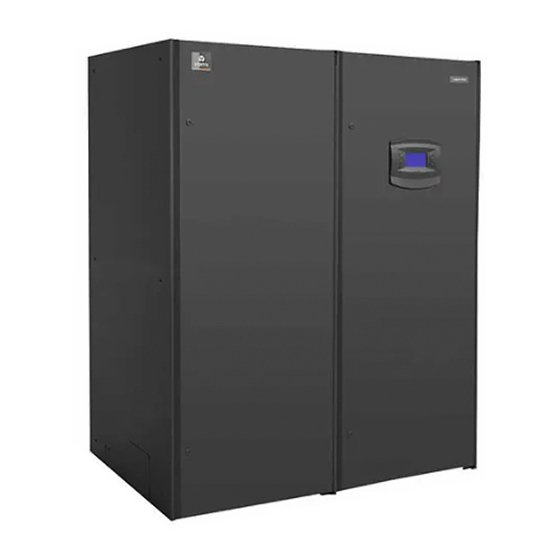
Chapter1 Overview 1.2 Appearance Liebert.PEX+ appearance is shown in Figure 1-2 with P2080UA as an example. Figure 1-2 Appearance 1.3 Main Components and Optional Features The components include indoor unit, condenser and remote monitoring software. 1.3.1 Components of Indoor Unit The indoor unit includes compressor, evaporator, electronic expansion valve, infrared humidifier, DC speed-regulated centrifugal fan (“EC fan”... -
Page 11: Condenser
Plenum The upflow unit shall be configured with a plenum with its configuration listed in 3.3.3 Plenum dimensions (for upflow unit). For special plenum, please contact Emerson. Electrode humidifier Liebert.PEX+ AC shall have the option of electrode humidifier according to user requirements. The electrode humidifier has a different requirement for water inlet / outlet pipes with the standard infrared humidifier. -
Page 12: Chapter 2 Instructions For Installation Preparations
Chapter2 Instructions for Installation Preparations Chapter 2 Instructions for Installation Preparations Liebert.PEX+ is professional equipment, and there are lots of complex installation works, so the preparation is very important. This chapter details the installation preparation, including how to prepare the installation environment and space and reserve the maintenance space, and how to unpack and inspect. -
Page 13: Operating Environment
The Liebert.PEX+ series air conditioner is heavy (see Table 3-1 for the weight). It is recommended to use mechanical equipment such as an electric forklift to unload and move the equipment to the place close to the installation site. If an electric forklift is used, insert the tines of the forklift below the pallet, as shown in Figure 2-2. -
Page 14: Unpacking
1. Remove the side panels and top cover Liebert.PEX+ series air conditioner uses the international packaging. You can use a hammer or straight screwdriver to straighten the connection hook that connects the side panels to the top cover, as shown in Figure 2-4. -
Page 15: Inspection
Check against the Packing List that the fittings are complete and the components are intact. If any parts are found missing, or damaged, please report to the carrier immediately. If any hidden damages are found, please report to the local offices of the carrier and Emerson. Liebert. PEX+Series Precision Air Conditioner... -
Page 16: Chapter 3 Mechanical Installation
:Emerson piping. :Field piping (by technicians). *: Components are not supplied by Emerson but are recommended for proper circuit operation and maintenance. +: Components are required when the equivalent length exceeds 30m. Liebert. PEX+Series Precision Air Conditioner... -
Page 17: System Installation Illustration
Chapter3 Mechanical Installation 3.2.2 System Installation Illustration The installation modes of the unit are shown in Figure 3-2 and Figure 3-3. Outdoor unit Invert bend (higher than the top copper pipe of condenser) Liquid pipe (avoid direct sun shine) Oil trap Indoor unit Movable floor gas pipe slope... -
Page 18: Dimensions And Weight Of Condenser
Chapter3 Mechanical Installation Figure 3-4 Outline drawings of the upflow indoor unit (unit: mm) Figure 3-5 Outline drawings of the downflow indoor unit Table 3-1 Dimensions and weight of indoor unit Model Dimensions (W×D×H)(mm) Net weight (kg) P1020U(D)A13C 853×874×1970 P1025U(D)A13C 853×874×1970 P1030U(D)A13C 1130×995×1975... -
Page 19: Positions And Dimensions Of Air Outlet
P2080 to P2100 2230 400(600, optional) Note If the height of the plenum selected for air conditioner unit exceeds 600mm, consult Emerson for non-standard production. 3.3.4 Positions and dimensions of air outlet Base pallet cut-out location dimensions The cutout position and dimensions are shown in Figure 3-6. - Page 20 Chapter3 Mechanical Installation Position and dimensions of air outlet on top cover The position and dimensions of air outlet on top cover of upflow unit are shown in Figure 3-7 and Table 3-3. Figure 3-7 Position of air outlet on top cover of upflow unit Table 3-3 Dimensions of air outlet on top cover of upflow unit (unit:mm) Model P1020~P1025...
-
Page 21: Installing Indoor Unit
The base shall be made by the installation team according to the dimensions, weight and height of the unit to ensure the rigidness of the structure meets the requirement. User can make the base by himself or ask Emerson to make it. -
Page 22: Install Indoor Unit Cabinet
If the one-way equivalent length exceeds 30m, or if the vertical distance between indoor unit and condenser exceeds the values in Table 3-6, consult Emerson before installation to confirm whether a pipe extension kit is needed. The pipe sizes recommended are ‘equivalent lengths’, with the resistance caused by bends taken into account. See Table 3-5 for equivalent lengths of partial components, and the installer should confirm that the sizes are appropriate for the site conditions. -
Page 23: Connecting Water Inlet Pipe Of Humidifier
Chapter3 Mechanical Installation ! warning Because the infrared humidifier contains flowing hot water, the water pipe must be resistant to heat higher than 90° C. For the unit that uses electrode humidifier, the drain pipe of the condensate water must be able to withstand 120℃. -
Page 24: Connecting Copper Pipes (Discharge Pipe And Liquid Pipe) Between Indoor Unit And Condenser
Table 3-7, or consult the technicians in local Emerson office. 2. Connect the copper pipes in welding mode. The connection ball valves of the discharge pipe and liquid pipe of indoor unit are shown in Figure 3-12. -
Page 25: Installing Pipe Extension Kit (Optional, For Site Installation)
3.Consult Emerson if the line length exceeds 60m. 4. If the outdoor temperature of the unit is below-15℃, the low temperature kit shall be used, and please consult Emerson for details. 3.6.5 Installing pipe extension kit (optional, for site installation) When the equivalent length of the one-way pipe exceeds 30m, the pipe extension kit should be installed. - Page 26 Chapter3 Mechanical Installation Handle Bolt Sling Winch bracket Winch Lifting hole L shaped lifting Figure 3-14 Installing winch bracket 2. Turn the handle and use the hook of the winch to hook the middle round hole (see Figure 3-14) of the L shaped lifting component.
-
Page 27: Removing Fastener And Vibration Absorber
Chapter3 Mechanical Installation 5. Install the fixing bolts (see Figure 3-16, totally 4 PCS) of the fan. 6. Remove the hook from the L shaped lifting component, turn the handle clockwise, tidy the sling and remove the fixing bolts (see Figure 3-14, totally 4 PCS) of the winch bracket, and take out the winch and the bracket assembly. 7. -
Page 28: Installation Inspection
Chapter3 Mechanical Installation HWA plug terminal Plug terminal for water level switch Figure 3-18 Floating pole of high water-level switch Removing pipe fasteners To prevent the long copper pipes from scratching the metal plate and being damaged, the pipes are cushioned with foam or bound up before delivery. -
Page 29: Chapter 4 Electrical Installation
6. Before the wiring, use a voltmeter to measure the power supply voltage and make sure that the power supply has been switched off. 7. The applicable grid for this air conditioner: TN, TT star connection power system; consult Emerson for other connections. -
Page 30: Connecting Control Cables
Chapter4 Electrical Installation Figure 4-2 Enlarged view of power connector Note The cable sizes should meet the local wiring regulations. Table 4-1 Rated full load ampere (FLA) (unit: A) With heating No heating Standard 1-level electric 2-level electric Standard Model model with... -
Page 31: Connecting Solenoid Valve Of Pipe Extension Kit (Options, For Site Installation)
Chapter4 Electrical Installation Customized To general 37/38 shorted, alarm terminal, RS485 port alarm removed 24 is the upon remote common shutdown terminal Figure 4-3 Enlarged view of terminal block ! warning The connection personnel must take anti-static measures before connecting the control cables. Connecting water-under-floor sensor Each unit is equipped with a water-under-floor sensor. -
Page 32: Wiring Of Condenser
After confirming the above points, you can start the commissioning. The commissioning is a professional operation and please contact Emerson engineer to do this job. ! warning Do not power on the unit until Emerson authorized technical has checked and confirmed the unit. Liebert. PEX+Series Precision Air Conditioner User Manual... -
Page 33: Chapter 5 Icom Controller
Chapter 5 iCOM Controller Chapter 5 iCOM Controller The iCOM controller adopts menu operation. It can monitor, display and operate the precision cooling air conditioner and control the environment within a set range. This chapter expounds the LCD, button and indicator panel, structure chart of control menu, startup interface, main interface, USER MENUS, SERVICE MENUS, ADVANCED MENUS and EVENT NAME AND DIFINITION of the iCOM controller. - Page 34 Chapter 5 iCOM Controller The functions of the buttons are described in Table 5-2. Table 5-2 Function description of buttons Button Function description 1. Switch on/off the system. Press the ON/OFF button to shut down an operating system, or to start an idle system. ON/OFF 2.
-
Page 35: Structure Chart Of Control Menu
Please refer to Appendix3 Menu Structure Of iCOM Controller. 5.4 Startup Interface After the system is powered on, it is in the waiting state. The LCD will display the interface shown in Figure 5-3. EMERSON Network Power Figure 5-3 Startup interface 5.5 Main Interface... -
Page 36: User Menus
Chapter 5 iCOM Controller 5.6 USER MENUS Press the ENTER or DOWN button on the main interface to enter the USER MENUS, as shown in Figure 5-6. The USER MENUS are displayed in six pages, each displaying one or two submenus. Press the ENTER button to highlight the submenu, the up or down button to browse the submenus, and the ENTER button to enter the selected one. -
Page 37: Event Log
Chapter 5 iCOM Controller If you want to modify the preceding set points, you should input the password before entering the SET POINTS menu. Then press the ENTER button to highlight it and use the UP and DOWN button to scroll the options. Press the ENTER button to select one parameter, use the up or DOWN button to set the value, and press the ENTER button to save the change. -
Page 38: Set Alarms
Chapter 5 iCOM Controller 5.6.6 SET ALARMS The SET ALARMS menu is used to set the upper and lower limits of temperature and humidity alarms. The settings will not be lost when the power fails. You can select the ‘SET ALARMS’ submenu to browse and set the parameters through the USER MENUS. -
Page 39: Sensor Data
Chapter 5 iCOM Controller 5.6.7 SENSOR DATA You can monitor the data acquired by the sensors through the SENSOR DATA menu. The values are read only, no setting or change is allowed. The parameters are described in Table 5-7. Table 5-7 Descriptions of SENSOR DATA parameters Parameters Unit Description... -
Page 40: Display Setup
Chapter 5 iCOM Controller Parameters Unit Description Parameters Unit Description U316 Lo Humi Daily low humidity U339 AN IN 3: U317 Hi DewP Daily High Dew Point U340 AN IN 4: U317 Hi DP H Daily High Dew Point U317 Hi DP M Daily High Dew Point U317... -
Page 41: Sleep Mode
Chapter 5 iCOM Controller Table 5-9 Descriptions of TOTAL RUN HRS parameters Parameters Default Related component Parameters Default Related component U502 MOTOR(S) 1000hr U507 HG / HW 23hr Hot gas/hot water Fan motor U502 LIMIT 32000hr U508 EL HEAT1 Electric heater 1 U503 COMP1 500hr... -
Page 42: Service Menus
NETWORK SETUP Figure 5-9 SERVICE MENUS 5.7.1 PASSWORD LEVEL It is operated by Emerson service personnel. 5.7.2 SET POINTS Different from the SET POINTS in the USER MENUS, the SET POINTS in SERVICE MENUS has many more parameters. See Table 5-11 for the parameter descriptions. - Page 43 Chapter 5 iCOM Controller Parameters Default Setting range Description S122 2ND SETP 23.0 ° C 5.0-40.0 ° C Temperature Set point S124 HUM SENS Return Sensor REM,RET Humidity Control Sensor S125 HUM SET 50 % 20% ~ 80% Humidity Set Point S125 HUM SET 8.9 °...
-
Page 44: Standby
Chapter 5 iCOM Controller Parameters Default Setting range Description S168 BACKDRFT No,Yes Fan Back Draft Control S169 VSD BDR 1.5V 0.1 - 5.1V VSD Set point BACK DRAFT S171 NO BDR 1 3.5V 0.0 - 5.0V Not Selectable Zone 1 S172 NO BDR 2 0.0V... - Page 45 Chapter 5 iCOM Controller The WELLNESS menu includes nine groups of parameters, including WELLNESS BASICs, and WELLNESS MOTOR, WELLNESS COMPs, WELLNESS HEATs and WELLNESS HUM. See Table 5-13 ~ Table 5-22 for detailed parameter descriptions. WELLNESS BASIC1 Table 5-13 Descriptions of WELLNESS BASIC1 parameters Parameters Default Setting range...
- Page 46 Chapter 5 iCOM Controller Parameters Default Description S038 BEST Starts per day best S039 WORST Starts per day worst S040 HP AL Number of high pressure alarms occurred to compressor 2 since the last maintenance S041 LP AL Number of low pressure alarms occurred to compressor 2 since the last maintenance S042 OL AL Number of overload alarms occurred to compressor 2 since the last maintenance...
-
Page 47: Diagnostics
Chapter 5 iCOM Controller Parameters Default Description Bonus amount. Actual bonus calculated through the number of starts and average run time. S085 BONUS This value determines the time for the next maintenance WELLNESS ECO Table 5-22 Descriptions of WELLNESS ECO parameters Parameters Default Description... - Page 48 Chapter 5 iCOM Controller Parameters Default Setting range Description Diagnosis switch of electric heater 3. The ‘On’ setting of this S326 EL HEAT3 On, Off. parameter can start electric heater 3 only when the air loss is normal S327 SCR HEAT 0 ~ 100 % SCR Heat S328...
-
Page 49: Set Alarms
Chapter 5 iCOM Controller Parameters Default Setting range Description S374 Off, On S375 COND 2 Off, On S376 COND 1 S379 V_CTRL Time Time, Feedb Valve Control S380 V_CAL Yes. No Start Valve Calibration S381 CAL_STAT Idle Group 2 S382 CLSD 1 0.0-10.0V S383... - Page 50 Chapter 5 iCOM Controller Types Description Types Description Types Description C-In2 Customized alarm 2 FLOSD Flow AL SD ScRed D-Scroll Red C-In3 Customized alarm 3 FLOLC Flow AL LC Swap V Swap Valve C-In4 Customized alarm 4 ComPD Comp Lock PD ECFan EC Fan Fail Reheater lockout...
-
Page 51: Calibration
Chapter 5 iCOM Controller 5.7.7 CALIBRATION The CALIBRATION menu can calibrate sensors by setting offsets. The parameters are listed in Table 5-27. The parameters are in pairs: the former is the calibrated value and the latter is the calculated value, or the sum of the measured value and the calibrated value. -
Page 52: Network Setup
Chapter 5 iCOM Controller 5.7.8 NETWORK SETUP The NETWORK SETUP menu is used to set the parameters when the system is in a network subject to the monitoring of a host. See Table 5-28 for parameter descriptions. Table 5-28 Descriptions of NETWORK SETUP parameters Parameters Default Setting range... -
Page 53: Options Setup
Chapter 5 iCOM Controller 5.7.9 OPTIONS SETUP The OPTIONS SETUP menu is used to set the parameters according to the equipment-specific demands. See Table 5-29 for detailed descriptions. Table 5-29 Descriptions of OPTIONS SETUP parameters Parameters Default Setting range Description Auto, 1 (compressor 1 being the... -
Page 54: Advanced Menus
Figure 5-11 ADVANCED MENUS 5.8.1 PASSWORD LEVEL It is operated by Emerson service personnel. 5.8.2 FACTORY SETUP The FACTORY SETUP menu is displayed in nine pages. The parameters are described in Table 5-30 ~ Table 5-39. Unit code related settings... - Page 55 Chapter 5 iCOM Controller System related settings Table 5-31 Descriptions of system related settings Parameters (2/9) Default Setting range Description R407C, R22, A102 REFRIG Refrigerant type selection R410A Main fan overload. The action to take after the fan overload. Range: SHUTD, A103 MOTOR OL...
- Page 56 Chapter 5 iCOM Controller Free-cooling, HG and HW related settings Table 5-34 Descriptions of free-cooling, HG and HW related settings Parameters (5/9) Default Setting range Description A135 K11 ACT WNG、DEH、NOP、FC A136 C/W F DUR 3min 1min ~ 3min Cooling water flush duration A137 COOL TYP SINGL...
- Page 57 Chapter 5 iCOM Controller Table 5-37 Descriptions of analog output options Options Description Options Description CW010 CW/FC 0 ~ 10V ALBD2 AlarmBoard 2 Hot water ALBD3 AlarmBoard 3 HW175 Hot water 1.75 IVAR I-Variex 1 Variable fan speed drive HUM% HT HUM COOL Cooling...
-
Page 58: Mbv Settings
Chapter 5 iCOM Controller 5.9 MBV Settings Through the ADVANCED MENUS screen (see Figure 5-12), you can view the current status of the cooled valve. MBV menu is displayed in six pages, and the description of the menus is listed in Table 5-40. ADVANCED MENUS ACCESS MBV SETTINGS... -
Page 59: Event Name And Definition
Chapter 5 iCOM Controller Parameters Default Range Description A458 L1 default proportional band A459 L2A default proportional band A460 L2B default proportional band A461 L3 default proportional band A462 Min proportional band 5.10 EVENT NAME AND DEFINITION See Table 5-41 for event name and definition. Table 5-41 List of event name and definition Event Definition... - Page 60 Chapter 5 iCOM Controller Event Definition ON-OFF KEY DISABLED ON-OFFkey disabled LWD SENSOR FAIL Low water level sensor fails WATER LEAKAGE Water leakage alarm Dummy 67 Dummy alarm 067 RAM / Battery Failure RAM/battery failure Low Memory 1 Low memory 1 NO CONNECTION w/Unit1 No connection with unit 1 COMP 1 OVERLOAD...
- Page 61 Chapter 5 iCOM Controller Event Definition HIGH CABINET TEMP High cabinet temperature LOW CABINET TEMP Low cabinet temperature HIGH EXT DEWPOINT High external dewpoint LOSS OF POWER Loss of power REHEAT LOCKOUT Reheater lockout HEAT REJ VFD HEAT REJ VFD HUMIDIFIER LOCKOUT Humidifier lockout HEAT REJ TVSS...
- Page 62 Chapter 5 iCOM Controller Event Definition FEEDBACK SIGNAL 1 FAILURE Feedback signal 1 failure SUPPLY CW SENSOR FAILURE Supply chilled water sensor failure RETURN CW SENSOR FAILURE Return chilled water sensor failure SUPPLY REF SENSOR FAILURE Supply refrigerant sensor failure RETURN REF SENSOR FAILURE Return refrigerant sensor failure VALVE HRS EXCEEDED...
-
Page 63: Chapter 6 Application Of Intellislot
Installing host communication card The installation boxes 1 and 2 have been installed on the Liebert.PEX+ series air conditioner unit. If the host communication configuration is needed, insert the host communication card into the installation box 1 and tighten the screws, as shown in Figure 6-3. -
Page 64: Commission Of Host Communication Component
Chapter 6 Application Of INTELLISLOT Connecting cables The electrical schematic diagram of the host communication configuration is shown in Figure 6-4. Cables P61, P65 and P67 have been connected in factory. So you should only connect the host communication card to the monitoring center. -
Page 65: Setting 485 Communication Card
Chapter 6 Application Of INTELLISLOT Figure 6-6 Choosing serial port 3. In the Connect to interface, choose the serial port being used (such as ‘COM1’), and click OK, as shown in Figure 6-7. Figure 6-7 Setting port property 4. Set the communication parameters as shown in Figure 6-7 and click OK. 6.3.2 Setting 485 Communication Card Set the parameters of the 485 communication card according to the following procedures: After the HyperTerminal is set, you can click OK to display the following HyperTerminal interface. - Page 66 Chapter 6 Application Of INTELLISLOT Type ‘1’ and the following figure will appear. Type ‘1’ and select the Modbus protocol, and the following figure will appear. Type ‘3’ and select the ID used to communicate between the communication card and the host, and the following figure will appear.
-
Page 67: Setting Tcp/Ip Communication Card
If you type ‘x’, the setting can be saved. After the setting is saved, the 485 communication card will be restarted. 10. On the main interface, typing ‘4’ can view whether the communication status between the communication card and the Liebert.PEX+ series air conditioner is normal, as shown in the following figure. 6.3.3 Setting TCP/IP Communication Card Set the parameters of the TCP/IP communication card according to the following procedures: After the HyperTerminal is set, you can click OK to display the following HyperTerminal interface. -
Page 68: Setting Snmp Parameters Of Tcp/Ip Communication Card
After the setting is saved, the TCP/IP communication card will be restarted. 5. On the main interface, typing ‘5’ can view whether the communication status between the communication card and the Liebert.PEX+ series air conditioner is normal, as shown in the following figure. 6.3.4 Setting SNMP Parameters Of TCP/IP Communication Card After the HyperTerminal of the TCP/IP communication card is set, you can set the parameters of this communication card. - Page 69 IMU6100 IMU6100 Chapter 6 Application Of INTELLISLOT Video Video con Video Contro Controllab Contro Controllab Contro Came Camera s Came Came Camera s Came I M U6 1 0 0 IM U 6 1 0 0 Figure 6-8 Initial interface (1) Complete Config After the communication becomes normal, the interface shown in Figure 6-9 will appear.
- Page 70 Chapter 6 Application Of INTELLISLOT Figure 6-10 Configuration interface 3. Click Access under SNMP at the left side of the interface, as shown in Figure 6-11. Type the user name ‘Liebert’ and the password ‘Liebert’, and click OK to enter the configuration interface. ...
-
Page 71: Host Communication Networking Diagram
Chapter 6 Application Of INTELLISLOT Figure 6-12 NMS configuration interface of SNMP host monitoring center (1) 5. Expand the SNMP node at the left side of the interface shown in Figure 6-13 and click Traps to set IP Address, Port and Community of the NMS used for receiving Traps. After modifying, you must click Save to save the setting. Figure 6-13 NMS configuration interface of SNMP host monitoring center (2) 6.4 Host Communication Networking Diagram The networking diagram of the TCP/IP communication card (SNMP protocol) is shown in Figure 6-14. - Page 72 Chapter 6 Application Of INTELLISLOT Network cable connection Air conditioner 1 TCP/IP communication card Network cable Network cable connection connection Air conditioner 2 TCP/IP Monitoring center communication card Network cable connection Air conditioner n TCP/IP communication card Figure 6-14 Networking diagram of TCP/IP communication card ...
-
Page 73: Chapter 7 System Operation And Maintenance
Chapter 7 System Operation And Maintenance Chapter 7 System Operation And Maintenance This chapter introduces the operation and maintenance of the Liebert.PEX+ AC, including routine maintenance and inspection items, electrical connection inspection, control component appearance checking, and air cooled condenser, filter , infrared humidifier and electric heating maintenance guidance. -
Page 74: Self-Diagnosis Function
Chapter 7 System Operation And Maintenance Components Inspection items No leakage Compressor Check for noise and observe vibration condition Check and fix connectors Cleanliness of condenser fins Fan base is rigid. Check if vibration absorbing cushion is aging or damaged Air cooled condenser Check if SPD board(if any) is working, and check once a week in thunderstorm seasons. -
Page 75: Air Cooled Condenser
Chapter 7 System Operation And Maintenance 5. Check the connection between the user terminals (70#, 71#, 70A#, 71A#, 37#, 38#) and the control interface board. 6. Check the output connection between the control interface board and various contactors and solenoid valves for liquid pipes, and the input connection between control interface board and fan overload protector, high pressure switch, heating over-temperature protection switch, humidifier protection switches, discharge air temperature sensor, and low pressure sensor. -
Page 76: Infrared Humidifier
Chapter 7 System Operation And Maintenance service alarm is triggered. User needs to replace the filter based on the clogging condition of the filter. The filter must be checked once a month, and be replaced as required during operation. Note ... -
Page 77: Chapter 8 Troubleshooting
Chapter 8 Troubleshooting Chapter 8 Troubleshooting This chapter introduces the troubleshooting. ! warning Certain circuits carry lethal voltages. Only professional technicians are allowed to maintain the unit. Extra care should be taken when troubleshooting online. Note If jumpers are used for troubleshooting, remember to remove the jumpers after the troubleshooting, or the connected jumpers may bypass certain control function and damage the equipment. -
Page 78: Compressor And Cooling System Troubleshooting
Chapter 8 Troubleshooting Symptom Potential causes Items to be examined or handled 1) Check whether the fans L1, L2 and L3 are power-off, phase failure or undervoltage; 2) Check whether the analog signals output from P51 meet 0 ~ 10Vac requirements;... - Page 79 Chapter 8 Troubleshooting Symptom Potential causes Items to be examined or handled Too much refrigerant charging Check whether the subcooling degree is too high Check whether the LP sensor reading and actual pressure meet ± 0.6bar requirement (the HP sensor value HP protection Electric valve improperly set can be read from the SERVICE MENUS/DIAGNOSTICS,...
-
Page 80: Infrared Humidifier Troubleshooting
Chapter 8 Troubleshooting Symptom Potential causes Items to be examined or handled Set the preset temperature after the first startup, the unit The difference between room air return will power off, restart the system can run the FC system; temperature and setting temperature is when the unit is in normal state, but the FC fan stops for too high (more than A138 setting one hour, it means that the present refrigeration... - Page 81 Chapter 8 Troubleshooting Heating auxiliary relay failure Check the heating auxiliary relay and its cable In the case of two-stage heating, check terminals P34-1 and P34-2. If the heating system then starts to work, it means that the safety device is open. Remove the jumper Safety device of the heating and the electric heater, and check that the manual reset system is open...
-
Page 83: Appendix 1 Circuit Diagram
Appendix 1 Circuit Diagram Appendix 1 Circuit Diagram NOTES: PRIMARY P65 CONNECTION LINE 1. ALL FIELD WIRING TO BE PER LOCAL CODES. USE COPPER CONDUCTORS ONLY. SEE UNIT NAMEPLATE VOLTAGE 2. SEE INSTALLATION AND USER MANUAL(S). 65-1 12-1 ANALOG 13-1 TH/HU UNIT DISPLAY 66-1... -
Page 85: Appendix 2 Menu Structure Of Icom Controller (Users Menus)
Appendix 2 Menu Structure of Icom Controller (USERS MENUS) Appendix 2 Menu Structure Of iCOM Controller (USERS MENUS) USER MENUS EVENT LOG GRAPHICS SET ALARMS SENSOR DATA DISPLAY SETUP TOTAL RUN HRS SLEEP MODE SERVICE INFO ACTIVE ALARMS SETPOINTS U102 TEMP SET U602 SLEEP EN U502 MOTOR(S) U401 LANGUAG... -
Page 87: Appendix 3 Menu Structure Of Icom Controller (Service Menus)
Appendix 3 Menu Structure of Icom Controller (SERVICE MENUS) Appendix 3 Menu Structure Of iCOM Controller (SERVICE MENUS) SERVICE MENUS STANDBY SETTINGS WELLNESS BASIC SET ALARMS SETPOINTS DIAGNOSTICS CALIBRATION NETWORK SETUP OPTIONS SETUP SERVICE INFO S202 RTN SNSR S402 COMP SEQ S042 OL AL ANALOG2... -
Page 89: Appendix 4 Alarm Control Menu Table
Appendix 4 Alarm Control Menu Table Appendix 4 Alarm Control Menu Table Alarm control High TEMP Low TEMP High HUM Low HUM C1 HP C2 HP C1 LP C2 LP LP Sensor 1 Alarm LP Sensor 2 Alarm HP1 lock HP2 lock LP1 lock LP2 lock... -
Page 90: Appendix 5 Hazardous Substances Or Elements Announcement
×: Means the content of the hazardous substances in at least one of the average quality materials of the part is outside the limits specified in SJ/T11363-2006 Emerson Network Power Co., Ltd. has been committed to the design and manufacturing of environment-friendly products. It will reduce and eventually eliminate the harzardous substances in the products through unremitting efforts in research. However,... -
Page 91: Appendix 6 Monthly Routine Inspection Items
Appendix 6 Monthly Routine Inspection Items Appendix 6 Monthly Routine Inspection Items Date: _____________________________ Recorded by: _____________________________ Model: _____________________________ SN: _____________________________ Components Inspection items Remark Check if filter is clogged and damaged. Filter Clean the filter Check if fan blades are distorted. Bearings in good condition No leakage Compressor... -
Page 92: Appendix 7 Routine Inspection Items (Half A Year)
Appendix 7 Routine Inspection Items (Half A Year) Appendix 7 Routine Inspection Items (Half A Year) Date: _____________________________ Recorded by: ___________________________ Model: _____________________________ SN: ___________________________ Components Inspection items Remark Check if filter is clogged and damaged Filter Clean the filter Check if fan blades are distorted.
Need help?
Do you have a question about the Liebert.PEX+ Series and is the answer not in the manual?
Questions and answers