
Related Manuals for Emerson Liebert Prop Fan Condensing Unit


Summary of Contents for Emerson Liebert Prop Fan Condensing Unit
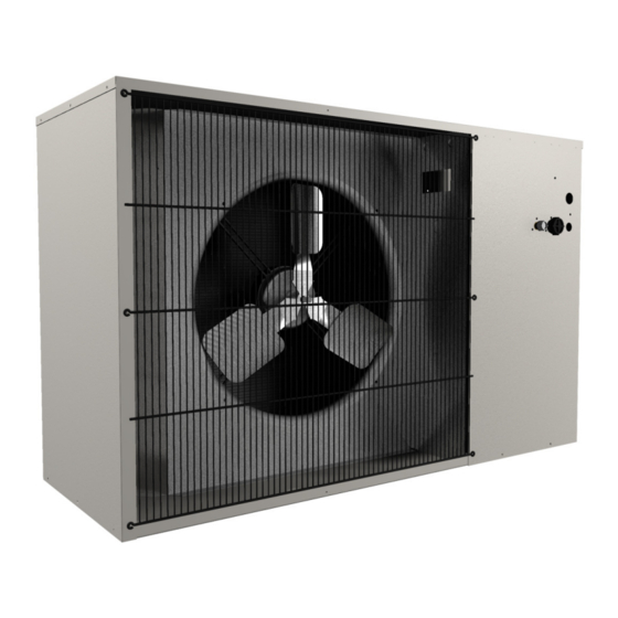
- Page 1 Precision Cooling For Business-Critical Continuity™ Liebert Prop Fan Condensing Unit ™ Installation, Operation and Maintenance Manual - 50 & 60Hz...
- Page 2 Figure i Model number nomenclature Example: PFH037A-PL7 — Prop Fan Condensing Nominal Capacity — = Standard Coil L = 95°F (35°C) Ambient Unit with Hot-Gas 1000 BTU/Hr C = Coated Coil Liebert Lee-Temp Bypass H = 105°F (41°C) Ambient Liebert Lee-Temp 0 = Standard Noise Level A = Air Cooled P = 208/230-1ph-60Hz...
-
Page 3: Table Of Contents
TABLE OF CONTENTS ...........1 RODUCT ESCRIPTION Prop Fan Condensing Units. - Page 4 FIGURES Figure i Model number nomenclature ......... Inside Front Cover Figure 1 Dimensions, horizontal air discharge .
-
Page 5: Product Description
Product Description RODUCT ESCRIPTION Prop Fan Condensing Units Liebert propeller fan condensing units are available in a range of sizes and configurations to offer flexibility in designing a precision environmental control system. The appropriate propeller fan con- densing unit paired with a corresponding Liebert fan coil evaporator model such as Liebert Data- Mate, Liebert Mini-Mate2 or Liebert Challenger 3000 is an effective solution for your environmental control application requirements. -
Page 6: Installation
When the unit arrives, inspect all items for any visible or concealed damage. Report any damage to the carrier immediately and file a damage claim; send a copy of the claim to Emerson Network Power or your local Emerson sales representative. -
Page 7: Dimensional Data
Installation Dimensional Data Figure 1 Dimensions, horizontal air discharge Removable (right) panel Fan Rotation for access to refrigeration component (left side) Right Air Discharge Left Air Intake Shaded area indicates a minimum clearance of 18" (457mm) for proper air flow. Shaded area indicates a recommended clearance of 24"... -
Page 8: Figure 2 Dimensions, Top Air Discharge
Installation Figure 2 Dimensions, top air discharge Top Air Guard Height Discharge Fan Rotation Right Air Intake Shaded area Left Air indicates a minimum Intake clearance of 18" (457mm) for proper air flow. 2" (51mm) Shaded area indicates a minimum Removable panel for access Shaded area clearance of 18"... -
Page 9: Figure 3 Dimensional Data, 277V Step-Down Transformer
Installation Figure 3 Dimensional data, 277V step-down transformer .31" (8mm) Dia. .281" (7mm) Dia. For rigid mounting For wall mounting and shipping 1/4-20 (2 screws & 1D18214P1 lock washers) for 10.3" (262mm) rigid mounting and 1D18214P2 shipping 11.68" (297mm) Remove screws & attach bracket 5.5"... -
Page 10: Piping And Electrical Connections
Installation Piping and Electrical Connections Figure 4 Piping and electrical connections, horizontal discharge Liquid Line Suction Line Quick Connect Quick Connect (Male Coupling) (Male Coupling) Electrical Entrance for High-Voltage Connection Electrical Entrance for Low-Voltage Connection DPN000132 Rev. 0 Table 3 Electrical and piping connections, horizontal air discharge Model Numbers Electrical Connections, in (mm) -
Page 11: Figure 5 Piping And Electrical Connections, Top Air Discharge
Installation Figure 5 Piping and electrical connections, top air discharge * System 2 (5 Ton) Electrical Entrance for High-Voltage Connection Liquid Line Quick Connect Electrical Entrance for (Male Coupling) Low-Voltage Connection * System 1 (3 Ton) Suction Line Quick Connect DPN000133 (Male Coupling) Rev. -
Page 12: Figure 6 General Piping Arrangement
Installation Figure 6 General piping arrangement SINGLE CIRCUIT = 1 - 5 Tons DUAL CIRCUIT = 8 Tons Condenser Coil High Pressure Switch Compressor * Liquid Injection Valve Bulb Hot Gas Bypass Solenoid Valve 3 - Way Head Pressure Relief Valve Suction Line Pressure Control Valve... -
Page 13: Figure 7 Electrical Field Connections, 1- To 5-Ton Units
Installation Figure 7 Electrical field connections, 1- to 5-ton units Field-supplied unit Field-supplied unit disconnect switch Single- or three-phase disconnect switch Single- or three-phase electric service not provided electric service not provided by Liebert by Liebert Field-supplied 24V Field-supplied 24V NEC Class 2 wiring NEC Class 2 wiring to evaporator module... -
Page 14: Figure 8 Electrical Field Connections, 8-Ton Units
Installation Figure 8 Electrical field connections, 8-ton units Field-supplied unit disconnect switch Single- or three-phase electric service not provided by Liebert Field-supplied 24V NEC Class 2 wiring to evaporator module Electric service Factory-wired connection to contactor to components on or terminal block electric panel Single- or three-phase electric service not provided by Liebert... -
Page 15: Figure 9 Single-Phase, 1-3 Ton Model Schematic, Typical
Installation Figure 9 Single-phase, 1-3 ton model schematic, typical Conductors Field-Supplied (See Note 5) NOMENCLATURE OUTDOOR CONDENSING MODULE EVAPORATOR UNIT Standard Devices BDR -- Bleed Resistor Unit Alarm C1 -- Condenser Contactor Input Connection CAP1 -- Compressor Capacitor CAP2 -- Fan Motor Capacitor CAP3 -- Compressor Capacitor 24V Power Supply... -
Page 16: Figure 10 Three-Phase, 3-5 Ton Model Schematic, Typical
Installation Figure 10 Three-phase, 3-5 ton model schematic, typical Conductors Field-Supplied (See Note 5) NOMENCLATURE OUTDOOR CONDENSING MODULE EVAPORATOR UNIT Standard Devices Unit Alarm C1 -- Condenser Contactor Input CAP2 -- Fan Motor Capacitor Connection CHTR -- Compressor Heater COMP -- Compressor F1 -- Transformer Fuse 1 24V Power F2 -- Transformer Fuse 2... -
Page 17: Figure 11 Three-Phase, 8 Ton Model Schematic, Typical
Installation Figure 11 Three-phase, 8 ton model schematic, typical Conductors Field-Supplied (See Note 5) OUTDOOR CONDENSING MODULE STANDARD DEVICES Evaporator Unit C1 - Compressor Contactor 1 HIGH HEAD 1 C2 - Compressor Contactor 2 See Note 6 CHTR1 - Compressor Heater 1 COOLING 1 CHTR2 - Compressor Heater 2 C1 Aux. -
Page 18: Piping Considerations
Installation Piping Considerations The Liebert Mini-Mate2, Liebert DataMate and the 3-ton Liebert Challenger 3000 split system units are designed with quick-connect fittings and are factory-charged to proper refrigerant levels. This permits connecting units without brazing inside critical spaces. These split systems require two refrigerant lines—an insulated copper suction line and a copper liquid line—between the evaporator and condensing units. -
Page 19: Figure 12 Refrigerant Piping Diagram
Installation Figure 12 Refrigerant piping diagram Pitch down 1/2" (13mm) per 10 ft. (3m) Evaporator NOTE When installing remote condensing units below the NOTE evaporator, the suction gas line should be trapped When installing remote condensing units below the with an inverted trap to the height of the evaporator. evaporator, the suction gas line should be trapped with This prevents refrigerant migration to the compres- an inverted trap to the height of the evaporator . -
Page 20: Pre-Charged Line Sets
Installation 2.5.2 Pre-Charged Line Sets Liebert pre-charged line sets are available in 15 ft (4.5m) and 30 ft (9m) lengths (see Table 7). NOTICE Risk of improper handling and installation of pre-charged lines. Can cause kinks and similar damage to lines. Care must be taken to prevent kinking the pre-charged lines for 1-ton and 3.5-ton units. -
Page 21: Table 8 Liebert Pfh Unit Charge Levels And Coupling Size
Installation Table 8 Liebert PFH unit charge levels and coupling size Model Numbers R-407C Charge Coupling Size 60 Hz 50 Hz lb-oz (kg) Liquid Suction 95°F (35°C) Standard Sound PFH014A-_L7 PFH013A-_L7 PFH020A-_L7 PFH019A-_L7 8-6 (3.8) PFH027A-_L7 PFH026A-_L7 PFH037A-_L7 PFH036A-_L7 13-5 (6.04) PFH042A-_L7 PFH041A-_L7 PFH067A-_L7... -
Page 22: Installation Of Piping To Units
Installation 2.5.4 Installation of Piping to Units NOTE When using hard piping, complete all piping and evacuate the lines before connecting quick-connects. NOTE Liebert Challenger 5-ton evaporator includes a nitrogen holding charge only. This holding charge must be evacuated and unit placed in a 250 micron vacuum prior to connecting piping. See Table 12 for field charge required. - Page 23 1. Install a stub tube kit on the existing line set connecting to the new condensing unit. This kit is available from Emerson or your local Emerson representative. 2. Evacuate the evaporator-piping system twice to a minimum 250 microns, breaking the vacuum with dry nitrogen each time.
-
Page 24: General System Charge Requirements
Installation 2.5.6 General System Charge Requirements Liebert split system units are designed with quick-connect fittings and are factory-charged to proper levels. Due to the wide range of operating ambients and sensitivity of the system components to charge level, the system charge must be maintained at recommended levels. If there is any doubt that the system has the correct refrigerant charge level, the correct procedure is to remove the entire system charge, evacuate the system and weigh in the recommended factory charge total for both units and any line sets or field piping. -
Page 25: Electrical Connections
Installation Electrical Connections Each unit is shipped from the factory with all internal wiring completed. All power, control wiring and ground connections must be made in accordance with the National Electrical Code and local codes. Refer to equipment nameplate regarding wire size and circuit protection requirements. Refer to Figures 5, 7 and 8 and electrical schematic (reference Figures 9 through 11) when making connec- tions. -
Page 26: Electrical Data
Installation Electrical Data Table 16 Electrical data—Standard sound and ambient models (95°F/35°C) 60Hz Nominal Input Voltage- Phase Capacity * Electrical Model # Tons Characteristic 208/230-1 208/230-3 460-3 575-3 — — — 10.2 — — — — — — 12.1 — —... -
Page 27: Table 18 Electrical Data-Quiet-Line Models (95°F/35°C) 60Hz
Installation Table 18 Electrical data—Quiet-Line models (95°F/35°C) 60Hz Nominal Input Voltage-Phase Capacity * Electrical Model # Tons Characteristic 208/230-1 208/230-3 460-3 575-3 13.0 — — — 16.0 — — — — — — 18.8 12.3 23.3 15.2 — 14.8 — 18.3 —... -
Page 28: Checklist For Completed Installation
Installation Table 21 Electrical data - Quiet-Line models (95°F/35°C) 50Hz Nominal Input Voltage-Phase Capacity * Electrical Model # Tons Characteristic 220-1 200/230-3 380/415-3 — — — — — — 12.3 — 18.0 — — 17.3 — 22.5 12.4 — — —... -
Page 29: Operation
Operation PERATION Compressor The scroll compressor is equipped with a band type crankcase heater to resist liquid refrigerant migration into the compressor during the Off cycle. The three-phase scroll compressor requires proper phasing to ensure correct motor rotation. The component connections have been phase synchronized at the factory. -
Page 30: Hot Gas Bypass
Operation Hot Gas Bypass 3.4.1 Operation When applying hot gas bypass with split system condensing units, bypassing discharge gas to the compressor suction line offers more flexibility than conventional hot gas bypass to the evaporator unit. The hot gas bypass valve is installed between the compressor discharge piping and suction piping, bypassing the condenser and evaporator coils. -
Page 31: Figure 13 Hot Gas Bypass Diagram
Operation Figure 13 Hot gas bypass diagram... -
Page 32: Maintenance
Maintenance AINTENANCE General Access the condensing unit by removing the unit housing panel. Clean the air cooled condenser coil of all debris that will inhibit airflow. This can be done with compressed air or with a commercial coil cleaner. Check for bent or damaged coil fins and repair as necessary. During winter, do not permit snow to accumulate on or around the condensing unit. -
Page 33: Compressor Replacement
Maintenance Compressor Replacement Replacement compressors are available from Emerson. They will be shipped in a permanent crate to the job site as required by the service contractor. Upon shipping a replacement compressor, the service contractor will be billed in full for the compres- sor. -
Page 34: Field Charge Verification
Maintenance Field Charge Verification An integral sightglass is provided with the receiver to assist in field charge verification. During charge verification set the control temperature down to keep the system running. If the system is equipped with hot gas bypass, de-energize it by removing power from the hot gas solenoid valve coil. To remove power, disconnect the solenoid leads from the unit contactor in the electric box (refer to specific unit schematic;... -
Page 35: Troubleshooting
Troubleshooting ROUBLESHOOTING Table 23 Troubleshooting Problem Cause Remedy No power to unit Check voltage at input terminal block. Check for 24VAC ±2VAC at control connections 1 & 2. If no voltage, check control setting requires cooling. If there Compressor contactor not pulling in is voltage, lockout relay may be energized. - Page 36 Racks & Integrated Cabinets Connectivity Embedded Power Power Switching & Controls Services DC Power Monitoring Precision Cooling Surge Protection Business-Critical Continuity, Emerson Network Power and the Emerson Network Power logo are trademarks and service marks of Emerson Electric Co. ©2008 Emerson Electric Co.
Need help?
Do you have a question about the Liebert Prop Fan Condensing Unit and is the answer not in the manual?
Questions and answers
What cooling capacity is the following unit? Model: PFH027A-PL3