
Subscribe to Our Youtube Channel
Related Manuals for INDIWORK IW06B-N23


Summary of Contents for INDIWORK IW06B-N23
- Page 1 Release Date: 2019 – 02 – 08 Instruction Manual High-Definition Link for BMW IW06B-N23 Model Name IW06B-N23 2019 – 01 - 29 Latest Firmware Date Manual Version Rev. 2.7 Language English...
-
Page 2: Table Of Contents
Contents • Cautions _____________________________________________________________ 3 • Dimension & Exterior _________________________________________________ 4 • Components & Optional parts _________________________________________ 5 • Full Installation Diagram ______________________________________________ 6 • HDMI Connection Diagram ____________________________________________ 7 • Navigation Connection Diagram _______________________________________ 8 • Compatibility Chart for Navigation(GPS) box models _____________________ 9 •... -
Page 3: Cautions
Navigation(GPS) box-related • When you connect the power wires(B+, ACC) to the navigation(GPS) box, the ‘NAVI (12V) OUT' wire supported by IW06B-N23 should be spliced with an ACC wire of navigation box. • After installation is done, select an applicable navigation(GPS) box model in the 'Navigation model selection menu' of setting mode. -
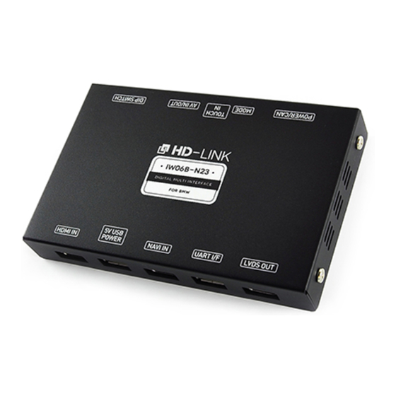
Page 4: Dimension & Exterior
Dimension ⓐ ⓑ ⓒ ⓓ ⓔ Exterior ⓐ DIP SWITCH ⓑ AV IN / OUT ⓒ TOUCH IN (Not Used) ⓓ MODE ⓔ POWER / CAN ⓕ HDMI IN ⓖ 5V USB POWER ⓗ NAVI IN ⓘ UART I/F ⓙ LVDS OUT ⓕ... -
Page 5: Components & Optional Parts
Power / CAN Cable LVDS Cable LVDS PCB HDMI Cable AV IN / OUT Cable 5-pin Micro USB Cable (For LVDS) Optional Parts (sold separately at the indiwork) HDMI Cable HDMI Extender Mode Switch (Male to Male) (For stick type HDMI device) -
Page 6: Full Installation Diagram
Full Installation Diagram ※ CAN HIGH / LOW Pin Specification NAVI 12V Power Output 네비게이션용 12V 전원 출력 (ACC 12V OUT) (NAVI 12V OUT) ※ Optional External Devices 내비게이션 전원 접지(GROUND) GND Output(GROUND) Mode Switch (optional) RV-CAM Video Input External Rear View 12V Power Output &... -
Page 7: Hdmi Connection Diagram
HDMI Connection Diagram HDMI Device HDMI Device HDMI IN 5V USB NAVI IN UART I/F LVDS OUT HDMI IN 5V USB NAVI IN UART I/F LVDS OUT POWER POWER HDMI HDMI HDMI HDMI (5V-1A Power output for HDMI Device) (5V-1A Power output for HDMI Device) (Male) (Female) (HDMI Extender) -
Page 8: Navigation Connection Diagram
Navigation Connection Diagram Navigation Connection Diagram Navigation(GPS) Box Navigation(GPS) Box HDMI IN 5V USB NAVI IN UART I/F LVDS OUT HDMI IN 5V USB NAVI IN UART I/F LVDS OUT POWER POWER HDMI HDMI Touch screen panel Touch screen panel (USB cable connecting is for ‘N-Link’... -
Page 9: Compatibility Chart For Navigation(Gps) Box Models
(HDMI to HDMI) ↑ MYVI South Korea MS1400 Digital OFF(↓): 1, 2, 3 HDMI Cable ON(↑) : 4 (HDMI to HDMI) • The 'IW06B-N23(HD-Link)' supports navigation(GPS) box models equipped with 'Digital video output'. • It does not support the 'RGB video signals'. -
Page 10: Lvds Connection Diagram
LVDS Connection Diagram LVDS Connection HDMI IN 5V USB NAVI IN UART I/F LVDS OUT POWER Monitor(OEM) HDMI • 'Genuine(OEM) LVDS connector' should be connected to 'LVDS IN / OUT PCB'. • ‘Provided LVDS connector' should be connected to the monitor instead to the genuine connector. -
Page 11: Hazard Module Connection
Hazard Module Connection POWER / CAN AV IN / OUT DIP SWITCH MODE TOUCH-IN Hazard button 6-pin Hazard connector Old Version Module New Version Module Hazard Hazard Module Module (4-Pin) (3-Pin) 핀 # 5 = Hazard(-) (Brown/Blue) 핀 # 5 = Hazard(-) (Orange) *MINI Cooper 핀... -
Page 12: Body Connector Specifications
Body Connector specifications MODE TOUCH-IN DIP SWITCH AV IN / OUT POWER / CAN Length: 20 cm Length : 100 cm Length: 150 cm BATTERY POWER INPUT RV-CAM VIDEO INPUT GND(RV-CAM VIDEO) GND INPUT RV-CAM POWER OUT GND OUTPUT(RV-CAM) GND OUTPUT REVERSE DETECTION IR OUT ACC(12V) POWER OUTPUT... -
Page 13: Car Compatibility Chart
1 Series 2012 - F20, F21 2 Series 2014 - 3 Series 2012 - F30, F31, F34(3 GT) The IW06B-N23 is used in 4 Series 2014 - F32, F33, F36 combination 5 Series 2012 - F10, F11, F07(5 GT) with BMW iDrive CIC-HIGH(NBT) system. -
Page 14: Activation By Original Buttons Of Bmw
Activation by original buttons of BMW For BMW & MINI Cooper Button Function Operation Remarks Changing Order: HDMI → NAVI → AV2 → OEM Press the button 2 seconds long. Modes MENU < OEM → NAVI > Press the button 2 times. Shortcut to each modes <... -
Page 15: Dip Switch Settings
DIP Switch Settings ON: ▼ OFF:▲ No.6 No.7 No.8 No.9 No.10 Car Models ON(▼) OFF(▲) 5(F10), 6(F12), 7(F01),X5(F15) OFF(▲) OFF(▲) OFF(▲) OFF(▲) OFF(▲) X3(F25), X4(F26), (10.2인치 / 8.8inch screen) HDMI Mode Skip HDMI Mode Navigation Mode Skip Navigation Mode 1(F20), 2(F22), 3(F30), 4(F32), ON(▼) OFF(▲) OFF(▲) - Page 16 DTV Diagram POWER / CAN AV IN / OUT DIP SWITCH MODE TOUCH-IN No.6 No.7 No.8 No.9 No.10 Car Models ON(▼) OFF(▲) ASUKA DTV. Selection of car model *JAPAN ON(▼) ON(▼) ALPINE - TUE-T500 · DTV IR Cable Remote Control DVB-TV IR Sensor OEM Button Function...
-
Page 17: Settings
Settings For BMW & MINI Cooper Button Function Operation Enter into the OPTION Press the button 5 seconds long. setting menu Back to previous BACK Press the button short. menu Select the menu Selection Press the button short. and setting values. Move the menu- Turn the dial Move the pointer and setting... -
Page 18: Hdmi Mode Settings
Settings 2. HDMI mode settings - Mode selection: HDMI ↔ NAVI - Image display = Adjust the values of brightness and contrast Red-Green-Blue colors of HDMI display. - Screen position & size Entry Disabled / Not applicable. 3. NAVI mode settings - Mode selection: NAVI ↔... -
Page 19: Rear View Camera Settings
Settings 4. Rear view camera settings - Parking guide lines = Adjust position of parking guide lines and select the lines ‘ON or OFF’. - Parking distance control = Adjust the position of parking distance control sensors to ‘LEFT or RIGHT’ and select the PDC ‘ON or OFF’. - Image display = Adjust the values of brightness and contrast Red-Green-Blue colors of Rear view camera display. -
Page 20: Automatic Activation Function(Av1)
Settings 6. Automatic activation function(AV1) - Shift gear from reverse to drive - Shift gear from parking to drive * When you shift gear ‘from reverse to drive’ or ‘from parking to drive’, it just works automatically during the activation time you selected. 7. -
Page 21: Keep The Rear Camera View
Settings (SURROUND VIEW OPTION) Keep the rear camera view - Shift gear from reverse to drive - Shift gear from parking to drive * When you shift gear ‘from reverse to drive’ or ‘from parking to drive’, it just works during the activation time you selected. -
Page 22: System Settings
- Factory default = Reset all setting values to factory default setting. 9. System information - Mode name : IW06B-N23 - Firmware date : 2016 – 11 – 21 (Latest firmware date) - = You can check the current firmware version date. -
Page 23: Information Of Dip Switch Settings
Settings 10. Information of Dip switch settings * You can check the current positions of dip switch settings. ex 1) ex 2) Actual DIP switch values. (→) Actual DIP switch values. (→) Appears on the setting menu. (↓) Appears on the setting menu. (↓) - Page 24 Copyright ⓒ indiwork. All Rights Reserved.
Need help?
Do you have a question about the IW06B-N23 and is the answer not in the manual?
Questions and answers