Table of Contents
Advertisement
Quick Links
Advertisement
Table of Contents

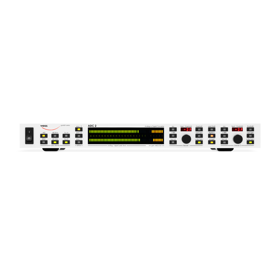
Summary of Contents for WEISS GAMBIT ADC2
- Page 1 Florastrasse 42, 8610 Uster, Switzerland +41 44 940 20 06 +41 44 940 22 14 http://www.weiss.ch / http://www.weiss-highend.com WEISS GAMBIT ADC2 OPERATING MANUAL Software Version: Firewire option update 22.7.2020...
- Page 2 OPERATING INSTRUCTIONS FOR GAMBIT ADC2 24Bit / 192kHz A/D CONVERTER INTRODUCTION INTRODUCTION Congratulations on purchasing the Weiss Gambit Series ADC2 A/D Converter ! The ADC2 is a two channel A/D converter designed for Summary of ADC2 features: most demanding audio applications. It uses state of the art A/D chips in Weiss Engineering’s proven “corre-...
- Page 3 OPERATING INSTRUCTIONS FOR GAMBIT ADC2 24Bit / 192kHz A/D OPERATING INSTRUCTIONS FOR GAMBIT ADC2 24Bit / 192kHz A/D CONVERTER CONVERTER INTRODUCTION INTRODUCTION OPERATING INSTRUCTIONS FOR GAMBIT ADC2 24Bit / 192kHz A/D OPERATING INSTRUCTIONS FOR GAMBIT ADC2 24Bit / 192kHz A/D...
-
Page 4: Operation
OPERATING INSTRUCTIONS FOR GAMBIT ADC2 24Bit / 192kHz A/D CONVERTER OPERATION OPERATION ADC2 Block Diagram Fig. 1 ADC2 Block Diagram Schematic pressor / limiter links the sidechains of the two chan- Input Control Panel nels. Typical applications for “ganged” mode are... -
Page 5: Output Gain
OPERATING INSTRUCTIONS FOR GAMBIT ADC2 24Bit / 192kHz A/D CONVERTER OPERATION Digital In / Mic The level bargraph is switched between input and output in the same manner as the peak hold. Thus, if Pressing the “digtial in” key activates the digital the “input gain”... - Page 6 OPERATING INSTRUCTIONS FOR GAMBIT ADC2 24Bit / 192kHz A/D CONVERTER OPERATION Threshold If “threshold” is lit, the rotary knobs control the threshold of the compressor section. The value is shown in the numeric display. If “peak hold” is active, the output peak value is displayed.
-
Page 7: Sampling Frequency
OPERATING INSTRUCTIONS FOR GAMBIT ADC2 24Bit / 192kHz A/D CONVERTER OPERATION POW-r Dither Sync and Dither Control Panel To requantize the input signal from 24bit to 16bit format, a special technique is used to avoid distortion, called dithering. Many dithering schemes are available today, both professional and homebrewed. - Page 8 OPERATING INSTRUCTIONS FOR GAMBIT ADC2 24Bit / 192kHz A/D CONVERTER OPERATION Why dither? To view the frequency characteristics of the three POW-r algorithms, refer to POW-R Noise Spectrum on If the 24bit digital signal is not dithered when record- p. 15.
-
Page 9: Dip Switches
OPERATING INSTRUCTIONS FOR GAMBIT ADC2 24Bit / 192kHz A/D CONVERTER OPERATION AES OUT DUAL WIRE Dip Switches If this switch is in the up position, the ADC2 outputs a dual-wire signal. Refer to Table 2 and Table 3 to look up exact output configurations depending on this dip switch. - Page 10 OPERATING INSTRUCTIONS FOR GAMBIT ADC2 24Bit / 192kHz A/D CONVERTER OPERATION DITHER MODE In the audio setup of your computer select the Weiss Firewire Interface as the recording and/or playback This switch determines how dither is applied to XLR device.
-
Page 11: Technical Data
OPERATING INSTRUCTIONS FOR GAMBIT ADC2 24Bit / 192kHz A/D CONVERTER TECHNICAL DATA TECHNICAL DATA Analogue Line Inputs 2 channels, symmetrical, not earth free, on two XLR female connectors, pin 2 hot. Input Impedance > 5kOhm Analogue Microphone Inputs 2 channels, symmetrical, not earth free, on two XLR female connectors, pin 2 hot. - Page 12 OPERATING INSTRUCTIONS FOR GAMBIT ADC2 24Bit / 192kHz A/D CONVERTER TECHNICAL DATA S/PDIF Output Output fs range: 44.1kHz 48.0kHz 88.2kHz 96.0kHz 176.4kHz 192.0kHz Maximum Output Wordlength: 24 Bits Channel Status Data: Professional format Connector: RCA female Impedance: 75 Ohm WORDSYNC I/O...
-
Page 13: Frequency Response
OPERATING INSTRUCTIONS FOR GAMBIT ADC2 24Bit / 192kHz A/D CONVERTER TECHNICAL DATA Low cut frequency response: 1st order highpass, 3dB point at 40Hz Frequency Response: @ fs = 44.1kHz: 20Hz ... > 20kHz +- 0.3dB @ fs = 48.0kHz: 20Hz ... > 20kHz +- 0.3dB @ fs = 88.2kHz: 20Hz ... -
Page 14: Parameter Tables
OPERATING INSTRUCTIONS FOR GAMBIT ADC2 24Bit / 192kHz A/D CONVERTER TECHNICAL DATA Parameter Tables Analogue Gain Line Input [dB]: -26.0, -25.0, -24.0, -23.0, etc. in 1dB steps to +16.0 (example: with a gain setting of -26.0, a +26dBu input signal generates a 0dBFS output) Analogue Gain Mic Input [dB]: -6.0, -5.0, -4.0, etc. - Page 15 OPERATING INSTRUCTIONS FOR GAMBIT ADC2 24Bit / 192kHz A/D CONVERTER TECHNICAL DATA POW-R Noise Spectrum Fig. 10 shows the noise spectrum of the three POW-R algorithms at 44.1 and 88.2 kHz. Fig. 10 Output spectrum with 80dBFS / 1kHz sine wave, dithered to 16 Bits, using the three POW-R algorithms at 44.1kHz and 88.2kHz respectively...


Need help?
Do you have a question about the GAMBIT ADC2 and is the answer not in the manual?
Questions and answers