Table of Contents
Advertisement
Available languages
Available languages
Quick Links
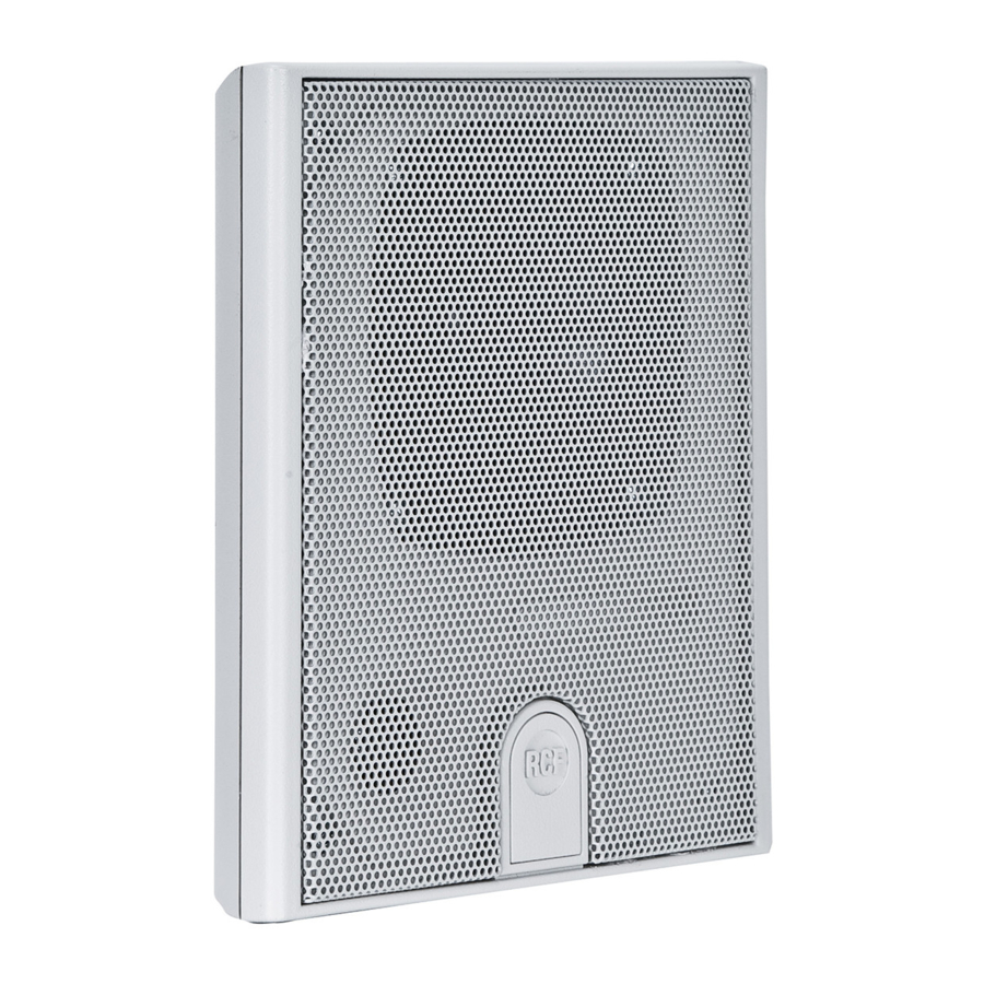
DU 31
DU 31AT
A 1331
OWNER MANUAL
MANUALE D'USO
-
WALL FLUSH MOUNT
LOUDSPEAKER
-
DIFFUSORE DA INCASSO
A PARETE
-
WALL FLUSH MOUNT
LOUDSPEAKER WITH
POWER SELECTOR
-
DIFFUSORE DA INCASSO
A PARETE CON
SELETTORE DI POTENZAE
-
REAR COVER
WITH ACCESSORIES
FOR DU 31 / DU 31AT
-
COPERCHIO POSTERIORE
CON ACCESSORI
PER DU 31 / DU 31AT
Advertisement
Table of Contents

Subscribe to Our Youtube Channel
Related Manuals for RCF DU 31


Summary of Contents for RCF DU 31
- Page 1 OWNER MANUAL MANUALE D’USO DU 31 WALL FLUSH MOUNT LOUDSPEAKER DIFFUSORE DA INCASSO A PARETE DU 31AT WALL FLUSH MOUNT LOUDSPEAKER WITH POWER SELECTOR DIFFUSORE DA INCASSO A PARETE CON SELETTORE DI POTENZAE A 1331 REAR COVER WITH ACCESSORIES FOR DU 31 / DU 31AT COPERCHIO POSTERIORE CON ACCESSORI PER DU 31 / DU 31AT...
-
Page 3: Table Of Contents
INDEX INDICE ENGLISH SAFETY PRECAUTIONS DESCRIPTION INSTALLATION CONNECTION SPECIFICATIONS ITALIANO AVVERTENZE PER LA SICUREZZA DESCRIZIONE INSTALLAZIONE COLLEGAMENTO DATI TECNICI... -
Page 4: Safety Precautions
IMPORTANT NOTES Before connecting and using this product, please read this instruction manual carefully and keep it on hand for future reference. This manual is to be considered an integral part of this product and must accompany it when it changes ownership as a reference for correct installation and use as well as for the safety precautions. RCF S.p.A. will not assume any responsibility for the incorrect installation and / or use of this product. SAFETY AND OPERATING PRECAUTIONS 1. All the precautions, in particular the safety ones, must be read with special attention, as they provide important information. 2. Loudspeaker lines (amplifier outputs) can have a sufficiently high voltage (i.e. 100-70 V) to involve a risk of electrocution: never install or connect this... - Page 5 9. RCF S.p.A. strongly recommends this product is only installed by professional qualified installers (or specialised firms) who can ensure a correct installation and certify it according to the regulations in force. The entire audio system must comply with the current standards and regulations regarding electrical systems. 10. There are numerous mechanical and electrical factors to be considered when installing a professional audio system (in addition to those which are strictly acoustic, such as sound pressure, angles of coverage, frequency response, etc.).
-
Page 6: Description
RCF S.P.A. THANKS YOU FOR PURCHASING THIS PRODUCT, WHICH HAS BEEN DESIGNED TO GUARANTEE RELIABILITY AND HIGH PERFORMANCE. DESCRIPTION DU 31 Wall flush mount 2 way loudspeaker, suitable for paging and background music. DU 31AT DU 31 loudspeaker with a power selector on the front. DU 31AT - POWER SELECTOR A 1331 Rear cover for DU 31 / DU 31AT with accessories for either wall surface mount (single or dual) or desk-top use. INSTALLATION WARNING: The loudspeaker is to be installed by qualified personnel, WARNING respecting all safety standards. The loudspeaker must be installed securely, making sure the support structure (walls / ceilings) has the necessary mechanical characteristics for the loudspeaker weight, without the risk of a fall that could damage things or cause an injury. Use attachment elements suitable for walls / ceilings (e.g. screw anchors for bricks, screw anchors for concrete, etc.). - Page 7 The loudspeaker can be fixed through the 4 screws of the box, drilling the loudspeaker in its corners (corresponding to the box holes, see picture 2). PICTURE 2 A 1331 REAR COVER This is an optional rear cover (with accessories) that allows the following alternatives: A single DU 31 / DU 31AT wall surface mount (straight, tilted or angled). Installation of a pair of loudspeaker. Desk-top use. The 4 corners allow to fix the loudspeaker through 4 screws. The rear cover has 5 points that can be drilled to get a hole necessary for the cable passage. A 1331 REAR COVER Example: rear view with central hole and a rubber grommet.
- Page 8 On the rear, there are 4 locations for the insertion of the supplied accessories and a point for a self-tapping screw. WALL MOUNT INSTALLATION WITH A 1331 Prepare the hole for the cable passage in the A 1331 rear cover. Install (only) the A 1331 rear cover to the wall through 2 dowels with 3.5 mm screws passing through the 2 fixing points indicated here in the picture. Remove the DU 31 / DU 31AT loudspeaker protective grille by using a small screwdriver. Connect the cable to the loudspeaker (see the ‘Connection’ manual section), then fix the loudspeaker to the A 1331 rear cover through the 4 front screws. A 1331 - FIXING POINTS Remount the loudspeaker protective grille. WALL MOUNT INSTALLATION WITH A 1331 As alternative, it is possible to install the loudspeaker tilted downwards, by using the 2 fixing points on the bottom oblique side.
- Page 9 ANGLED WALL MOUNT INSTALLATION WITH A 1331 (SINGLE OR A PAIR OF LOUDSPEAKERS) The A 1331 rear cover includes the ‘A’ accessory that permits the loudspeaker installation with a 45° horizontal angle. The 2 central holes of the ‘A’ accessory allow to fix the A 1331 rear cover (through two 3.5 mm self-tapping screws), the 2 lateral slots are for wall mount installation. ‘A’ ACCESSORY Proceed as follows: Install the ‘A’ accessory to the wall. Prepare the hole for the cable passage in the A 1331 rear cover. ANGLED WALL MOUNT Fix the A 1331 rear cover to the ‘A’ accessory through two 3.5 mm self- INSTALLATION WITH A 1331 tapping screws. (SINGLE OR A PAIR OF Remove the loudspeaker protective grille by using a small screwdriver. LOUDSPEAKERS) Connect the cable to the loudspeaker (see the ‘Connection’ manual section), then fix the loudspeaker to the A 1331 rear cover through the 4 front screws.
- Page 10 2 ‘A’ accessories put together with 2 lock pins allow the installation of a pair of loudspeakers pointed at different directions (90° angle between the 2 loudspeaker axes). 2 ‘A’ ACCESSORIES PUT TOGETHER WITH 2 LOCK PINS 90° Proceed as follows: Put together the 2 ‘A’ accessories through the 2 lock pins (included). Install the pair of ‘A’ accessories to the wall. Prepare the holes for the cable passage in the A 1331 rear covers. Fix each A 1331 rear cover to the respective ‘A’ accessory through two 3.5 mm self-tapping screws. Remove the loudspeaker protective grilles by using a small screwdriver. Connect the cable to both loudspeakers (see the ‘Connection’ manual section), then fix each loudspeaker to the respective A 1331 rear cover through the 4 front screws. Remount the loudspeaker protective grilles. A 1331 FIXING POINTS DESK-TOP (WITH A 1331 REAR COVER) The A 1331 rear cover includes the ‘B’ accessory (to be fixed to the rear through a self-tapping screw) that permits to place the loudspeaker on a desk.
-
Page 11: Connection
WARNING: loudspeaker connections should be only made by qualified and experienced personnel having the technical know-how or sufficient specific instructions to ensure that connections are made correctly and to prevent any electrical danger. To prevent any risk of electric shock, do not connect loudspeakers when the amplifier is switched on. Before turning the system on, check all connections and make sure there are no accidental short circuits. The entire sound system shall be designed and installed in compliance with the current local laws and regulations regarding electrical systems. DU 31 MODEL DU 31 MODEL On the loudspeaker rear there are screw terminals to connect a 100 V constant voltage line from an amplifier, with the choice of 3 different power values: 2 – 4 – 8 W. 70 V ( 100 V), if the liNe is iNstead of the selected power will be (1 – 2 – 4 w). - Page 12 DU 31AT MODEL DU 31AT MODEL On the loudspeaker rear there are a 100 V input to connect a 100 V constant voltage line (n: a 70 V entails half power) and a 25 V input to connect the COM 25V 100V loudspeaker (possibly in parallel to other loudspeakers, all connected through 25 V inputs) to an amplifier low impedance output (usually 4 – 8 Ω). The power can be set by means of the front power selector (that affects the volume level). 100 V CONSTANT 100 V CONSTANT VOLTAGE LINE: VOLTAGE LINE Connect the amplifier output marked with ‘0’, ‘b’ or ‘COM’ to the loudspeaker COM input. Connect the amplifier 100 V output (terminal marked with ‘100 V’ or ‘a’) to the loudspeaker 100 V input. 100 V 25 V coNNect the liNe to the loudspeaker iNput AMPLIFIER WITH LOW IMPEDANCE ( 4 – 8 Ω) AMPLIFIER WITH LOW LOUDSPEAKER OUTPUTS: IMPEDANCE ( 4 –...
- Page 13 Always use cables having wires with an adequate cross-section, considering the cable length and the total loudspeaker power. Loudspeaker lines must be kept separated from mains cable, microphone cables or others, in order to avoid inductive phenomena may cause hum or noises. Use loudspeaker cables having twisted wires to reduce hum caused by inductive effects due to coupling with electromagnetic fields. NOTES ABOUT LOW IMPEDANCE CONNECTIONS The total loudspeaker impedance must not be lower than the amplifier output impedance. Note: a loudspeaker total impedance equal to the amplifier output one permits to get the maximum deliverable power (but an higher loudspeaker impedance entails less power).
-
Page 14: Specifications
SPECIFICATIONS Input voltage 100 – 25 V Power 8 – 4 – 2 W (DU 31); max. 8 W selectable (DU 31AT) Frequency response 100 Hz ÷ 17 kHz Sensitivity 82 dB (1 m / 1 W) Sound pressure (8 W) 91 dB (1 m) Loudspeakers 4” woofer with piezoelectric tweeter Cabinet material Polystyrene UL94HB Grille Galvanized steel, Grey White RAL 9002 Colour Grey White RAL 9002 Dimensions (w, h, d) 151 mm, 175 mm, 56 mm Net weight 0.67 kg... -
Page 16: Avvertenze Per La Sicurezza
Il presente manuale costituisce parte integrante del prodotto e deve accompagnare quest’ultimo anche nei passaggi di proprietà, per permettere al nuovo proprietario di conoscere le modalità d’installazione e d’utilizzo e le avvertenze per la sicurezza. L’installazione e l’utilizzo errati del prodotto esimono la RCF S.p.A. da ogni responsabilità. AVVERTENZE PER LA SICUREZZA E PRECAUZIONI D’USO 1. Tutte le avvertenze, in particolare quelle relative alla sicurezza, devono essere lette con particolare attenzione, in quanto contengono importanti informazioni. - Page 17 9. La RCF S.p.A. raccomanda vivamente che l’installazione di questo prodotto sia eseguita solamente da installatori professionali qualificati (oppure da ditte specializzate) in grado di farla correttamente e certificarla in accordo con le normative vigenti. Tutto il sistema audio dovrà essere in conformità con le norme e le leggi vigenti in materia di impianti elettrici. 10. Vi sono numerosi fattori meccanici ed elettrici da considerare quando si installa un sistema audio professionale (oltre a quelli prettamente acustici, come la pressione sonora, gli angoli di copertura, la risposta in frequenza, ecc.). 11. Perdita dell’udito L’esposizione ad elevati livelli sonori può provocare la perdita permanente dell’udito. Il livello di pressione acustica pericolosa per l’udito varia...
-
Page 18: Descrizione
RCF S.P.A. VI RINGRAZIA PER L’ACQUISTO DI QUESTO PRODOTTO, REALIZZATO IN MODO DA GARANTIRNE L’AFFIDABILITÀ E PRESTAZIONI ELEVATE. DESCRIZIONE DU 31 Diffusore a 2 vie da incasso a parete adatto per la diffusione di annunci e musica di sottofondo. DU 31AT Diffusore DU 31 con selettore di potenza frontale (controllo di volume). DU 31AT - SELETTORE DI POTENZA A 1331 Coperchio posteriore per DU 31 / DU 31AT con accessori per l’installazione sporgente (singola o a coppie) e la predisposizione per la posa su tavolo. INSTALLAZIONE ATTENZIONE: l’installazione del diffusore deve essere effettuata da ATTENZIONE personale qualificato, rispettando gli standard di sicurezza. Eseguire un’installazione sicura del diffusore, controllando che la struttura di supporto (es. parete, soffitto, ecc.) abbia le necessarie caratteristiche meccaniche, tali da consentirgli di sopportare il peso del diffusore senza il pericolo di cadute che potrebbero compromettere l’incolumità di cose o persone. Utilizzare elementi di fissaggio adatti al tipo di struttura che deve sostenere il diffusore (es. tasselli per mattoni... - Page 19 Il fissaggio si effettua tramite le 4 viti fornite con la scatola, forando il diffusore agli angoli (in corrispondenza dei fori della scatola; figura 2). FIGURA 2 ACCESSORIO A 1331 Si tratta di un coperchio posteriore opzionale (con accessori) che permette una delle seguenti alternative: l’installazione sporgente a parete (dritta, inclinata od orientata) di un singolo diffusore DU 31 / DU 31AT; l’installazione di una coppia di diffusori; il posizionamento su tavolo. Nei 4 angoli è possibile avvitare viti autofilettanti per il fissaggio del diffusore. Il coperchio presenta 5 punti che possono essere forati per il passaggio del cavo. ACCESSORIO A 1331 Esempio: vista posteriore con foro centrale e gommino passacavo.
- Page 20 Sul retro, sono presenti 4 sedi per l’inserimento degli accessori a corredo e un punto per una vite autofilettante. INSTALLAZIONE A PARETE CON A 1331 Predisporre il foro per il passaggio del cavo nel coperchio posteriore A 1331. Installare il (solo) coperchio posteriore A 1331 alla parete tramite 2 tasselli con viti da 3,5 mm passanti nei 2 punti di fissaggio indicati. Rimuovere la griglia di protezione del diffusore DU 31 / DU 31AT facendo leva con un piccolo cacciavite. Collegare il cavo al diffusore (vedere la sezione “Collegamento” del manuale), A 1331 PUNTI DI FISSAGGIO poi fissare il diffusore al coperchio A 1331 tramite le 4 viti frontali. INSTALLAZIONE Riposizionare la griglia di protezione del diffusore. A PARETE CON A 1331 Come alternativa, è possibile installare il diffusore con una leggera inclinazione verso il basso, utilizzando i due punti di fissaggio sul lato obliquo.
- Page 21 INSTALLAZIONE ANGOLATA A PARETE CON A 1331, SINGOLA E DI UNA COPPIA DI DIFFUSORI A corredo del coperchio posteriore A 1331, è disponibile l’accessorio “A” che permette l’installazione del diffusore con un angolo orizzontale di 45°. I 2 fori centrali dell’accessorio A permettono il fissaggio del coperchio posteriore A 1331 (tramite 2 viti autofilettanti da 3,5 mm), le 2 asole servono per montaggio a parete. ACCESSORIO A In sequenza: installare l’accessorio “A” alla parete; INSTALLAZIONE predisporre il foro per il passaggio del cavo nel coperchio posteriore A ANGOLATA A PARETE CON 1331; A 1331, SINGOLA E DI fissare il coperchio posteriore A 1331 all’accessorio “A” tramite 2 viti UNA COPPIA DI DIFFUSORI...
- Page 22 2 accessori A uniti tra loro con 2 spine elastiche permettono l’installazione di una coppia di diffusori affiancati ed orientati (con un angolo tra i loro assi di 90°) in modo da coprire entrambe le direzioni. 2 ACCESSORI A DA UNIRE CON 2 SPINE ELASTICHE 90° In sequenza: unire 2 accessori “A” tramite le 2 spine elastiche a corredo; installare la coppia di accessori “A” alla parete; predisporre i fori per il passaggio del cavo nei coperchi posteriori A 1331; fissare i 2 coperchi posteriori A 1331 agli accessori “A”, ciascuno tramite 2 viti autofilettanti di 3,5 mm; rimuovere le griglie di protezione dei diffusori facendo leva con un piccolo cacciavite; collegare (vedere la sezione “Collegamento” del manuale) e montare ciascun diffusore DU 31 al rispettivo coperchio posteriore A 1331 tramite le 4 viti frontali; riposizionare la griglie di protezione dei diffusori. A 1331 PUNTI DI FISSAGGIO DIFFUSORE (CON COPERCHIO POSTERIORE A 1331) POSIZIONATO SU TAVOLO A corredo del coperchio posteriore A 1331, è disponibile l’accessorio “B” (da fissare sul retro tramite una vite autofilettante) che permette di posizionare un diffusore direttamente su un tavolo. ACCESSORIO B...
-
Page 23: Collegamento
ATTENZIONE: per il collegamento del diffusore si raccomanda di rivolgersi a personale qualificato ed addestrato, ossia per sonale avente conoscenze tecniche o esperienza o istruzioni specifiche sufficienti per permettergli di realizzare correttamente le connessioni e prevenire i pericoli dell’elettricità. Per evitare il rischio di shock elettrici, non collegare il diffusore con l’amplificatore acceso. Prima di far funzionare il diffusore, è buona norma ricontrollare tutte le connessioni, verificando in particolar modo che non vi siano dei cortocircuiti accidentali. Tutto l’impianto di sonorizzazione dovrà essere realizzato in conformità con le norme e le leggi vigenti in materia di impianti elettrici. MODELLO DU 31 MODELLO DU 31 Sul retro del diffusore è presente una morsettiera per il collegamento della linea a tensione costante 100 V proveniente dall’amplificatore, con la possibilità di scegliere la potenza tra 3 differenti valori (2 – 4 – 8 W); 70 V ( 100 V), uN eVeNtuale collegameNto ad uN liNea aNziché comporta il (1 – 2 – 4 w). - Page 24 MODELLO DU 31AT MODELLO DU 31AT Sul retro del diffusore è presente sia un morsetto 100 V per il collegamento della linea a tensione costante 100 V proveniente dall’amplificatore (n: COM 25V 100V un eventuale collegamento ad un linea 70 V comporta il dimezzamento della potenza), sia un morsetto 25 V per il collegamento del diffusore (eventualmente in parallelo ad altri diffusori, anche loro collegati tramite l’ingresso 25 V) ad un amplificatore con uscita a bassa impedenza (solitamente 4 – 8 Ω). La selezione della potenza (impostazione del volume) si effettua tramite il commutatore posto sul lato frontale del diffusore. LINEA A TENSIONE COSTANTE 100 V: LINEA A TENSIONE Collegare il morsetto COM del diffusore alla linea che fa capo a quello COSTANTE 100 V dell’amplificatore contrassegnato con “0”, “b” oppure “COM”. Collegare il morsetto 100 V del diffusore e collegarlo alla linea 100 V proveniente dall’amplificatore (morsetto contrassegnato con “100 V” o “a”). : NoN 100 V 25 V collegare la liNea al morsetto del diffusore AMPLIFICATORE CON USCITA DIFFUSORI...
- Page 25 Utilizzare dei cavi con conduttori aventi una sezione adeguata, considerando la loro lunghezza e la potenza complessiva dei diffusori. Per evitare che fenomeni induttivi diano luogo a ronzii, disturbi e compromettano il funzionamento del sistema, i cavi per i diffusori non devono essere canalizzati assieme ai conduttori dell’energia elettrica, ai cavi microfonici od altre linee. Per minimizzare gli effetti induttivi (ronzii) dovuti all’accoppiamento con campi elettromagnetici circostanti, utilizzare cavi con conduttori intrecciati.
-
Page 26: Dati Tecnici
DATI TECNICI Tensione d’ingresso 100 – 25 V Potenza 8 – 4 – 2 W (DU 31); max. 8 W selezionabile (DU 31AT) Risposta in frequenza 100 Hz ÷ 17 kHz Sensibilità 82 dB (1 m / 1 W) Pressione sonora (8 W) 91 dB (1 m) Altoparlanti woofer 4” con tweeter piezoelettrico Materiale del corpo Polistirolo UL94HB Griglia Acciaio zincato verniciato, bianco grigiastro RAL 9002 Colore Bianco grigiastro RAL 9002 Dimensioni (l, h, p) 151 mm, 175 mm, 56 mm Peso netto 0,67 kg... - Page 28 Salvo eventuali errori ed omissioni. Except possible errors and omissions. www.rcf.it RCF S.p.A. Italy Via Raffaello Sanzio, 13 42124 Reggio Emilia - Italy Tel +39 0522 274 411 Fax +39 0522 232 428 e-mail: info@rcf.it...
Need help?
Do you have a question about the DU 31 and is the answer not in the manual?
Questions and answers