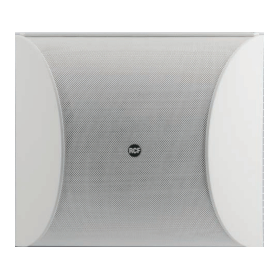
Summary of Contents for RCF DU100X
- Page 1 DU100X CEILING / WALL SURFACE MOUNTED LOUDSPEAKER DIFFUSORE PER INSTALLAZIONE SPORGENTE A PARETE O SOFFITTO User manual Manuale d’uso the rules of sound...
-
Page 3: Avvertenze Per La Sicurezza
Verificare inoltre l’idoneità del supporto (parete, soffitto, struttura ecc.) e dei componenti utilizzati per il fissaggio (tasselli, viti, staffe non fornite da RCF ecc.) che devono garantire la sicurezza dell’impianto / installazione nel tempo, anche considerando, ad esempio, vibrazioni meccaniche normalmente generate da un trasduttore. - Page 4 11. PERDITA DELL’UDITO L’esposizione ad elevati livelli sonori può provocare la perdita permanente dell’udito. Il livello di pressione acustica pericolosa per l’udito varia sensibilmente da persona a persona e dipende dalla durata dell’esposizione. Per evitare un’esposizione potenzialmente pericolosa ad elevati livelli di pressione acustica, è...
-
Page 5: Installazione A Parete
RCF S.p.A. Vi ringrazia per l’acquisto di questo prodotto, realizzato in modo da garantirne l’affidabilità e prestazioni elevate. CARATTERISTICHE • Installabile sia a parete sia a soffitto. • Corpo in materiale plastico di colore bianco. • Griglia metallica di protezione. - Page 6 Tramite le due asole , appendere il diffusore agli elementi di supporto precedentemente installati (ganci, chiodi, ecc.). Qualora si abbia l’esigenza di installare il diffusore a parete ruotato di 90°, utilizzare le due asole ed operare come indicato nel successivo paragrafo INSTALLAZIONE A SOFFITTO.
- Page 7 Svitare le quattro viti poste nella parte posteriore del diffusore e rimuovere il coperchio di protezione Selezionare eventualmente la potenza da diffondere, operando come indicato SELEZIONE nel successivo paragrafo DELLA POTENZA D’USCITA Tramite tabella seguente, selezionare i conduttori d’ingresso da utilizzare.
- Page 8 compromettano il funzionamento del sistema, i cavi per i diffusori non devono essere canalizzati assieme ai conduttori dell’energia elettrica, ai cavi microfonici od altre linee. • Per minimizzare gli effetti induttivi (ronzii) dovuti all’accoppiamento con campi elettromagnetici circostanti, utilizzare cavi con conduttori intrecciati.
-
Page 9: Schema Elettrico
SCHEMA ELETTRICO COLORI DEI CONDUTTORI nero verde arancio marrone bianco rosso giallo rosa grigio rosso AMPLIFICATORE... -
Page 10: Dati Tecnici
DATI TECNICI Potenza nominale 10 W (10-5-2,5-1,2-0,6 W) Impedenza: (ingr. 100 V) 1 kΩ (10 W); 2 kΩ (5 W); 4 kΩ (2,5 W); 8 kΩ (1,2 W); 16 kΩ (0,6 W) (ingr. 70 V) 0,5 kΩ (10 W); 1 kΩ (5 W); 2 kΩ (2,5 W); 4 kΩ (1,2 W); 8 kΩ (0,6 W) (ingr. - Page 12 DIMA DI FORATURA DRILLING TEMPLATE Execute holes for fixing at wall Fori per il fissaggio a parete...
- Page 13 Fori Ø 5mm Holes Ø 5mm Execute holes for fixing at ceiling Fori per il fissaggio a soffitto...
-
Page 16: Important Notes
(screw anchors, screws, brackets not supplied by RCF etc.), which must guarantee the security of the system / installation over time, also considering, for example, the mechanical vibrations normally generated by transducers. - Page 17 11. HEARING LOSS Exposure to high sound levels can cause permanent hearing loss. The acoustic pressure level that leads to hearing loss is different from person to person and depends on the duration of exposure. To prevent potentially dangerous exposure to high levels of acoustic pressure, anyone who is exposed to these levels should use adequate protection devices.
-
Page 18: Wall Installation
RCF S.p.A. would like to thank you for having purchased this product, which has been designed to guarantee reliability and high performance. FEATURES • It can be installed on walls and ceilings. • Body in white plastic. • Metallic protection grille. -
Page 19: Ceiling Installation
CEILING INSTALLATION Put the drilling template (included) on the wall at the loudspeaker installation selected point and use a pencil to mark the position of the two attachment points that correspond to the slots In the selected points, attach two screws with a head diameter longer than 5 mm (0.20”) and shorter than 9 mm (0.35”), in order to fit them into the loudspeaker slot... - Page 20 WIRE TO BE USED INPUT VOLTAGE 25 V BLACK (-) / BLUE (+) INPUT VOLTAGE 70 V BLACK (-) / BROWN (+) INPUT VOLTAGE 100 V BLACK (-) / RED (+) Connect the loudspeaker BLACK wire to the line negative wire (-) coming from the the amplifier output marked -, 0 or COM.
-
Page 21: Power Selection
POWER SELECTION DU 100X is equipped with a line transformer that makes it possible to select the power among different levels. The maximum power is the factory set; proceed as follows to change it: 1. Remove the protective rear cover (see paragraph CONNECTIONS) disconnect the RED wire from the terminal... -
Page 22: Specifications
SPECIFICATIONS Nominal power 10 W (10-5-2.5-1.2-0.6 W) Impedance: (100 V input) 1 kΩ (10 W); 2 kΩ (5 W); 4 kΩ (2.5 W); 8 kΩ (1.2 W); 16 kΩ (0.6 W) (70 V input) 0.5 kΩ (10 W); 1 kΩ (5 W); 2 kΩ (2.5 W); 4 kΩ (1.2 W); 8 kΩ (0.6 W) (25 V input) 63 Ω... - Page 24 Except possible errors and omissions. RCF S.p.A. reserves the right to make modifications without prior notice. the rules of sound RCF SpA: Via Raffaello, 13 - 42010 Reggio Emilia > Italy tel. +39 0522 274411 - fax +39 0522 274484 - e-mail: rcfservice@rcf.it...


Need help?
Do you have a question about the DU100X and is the answer not in the manual?
Questions and answers