Table of Contents
Advertisement
Quick Links
Advertisement
Table of Contents

Related Manuals for RP LIGHTING 1072-PC


Summary of Contents for RP LIGHTING 1072-PC
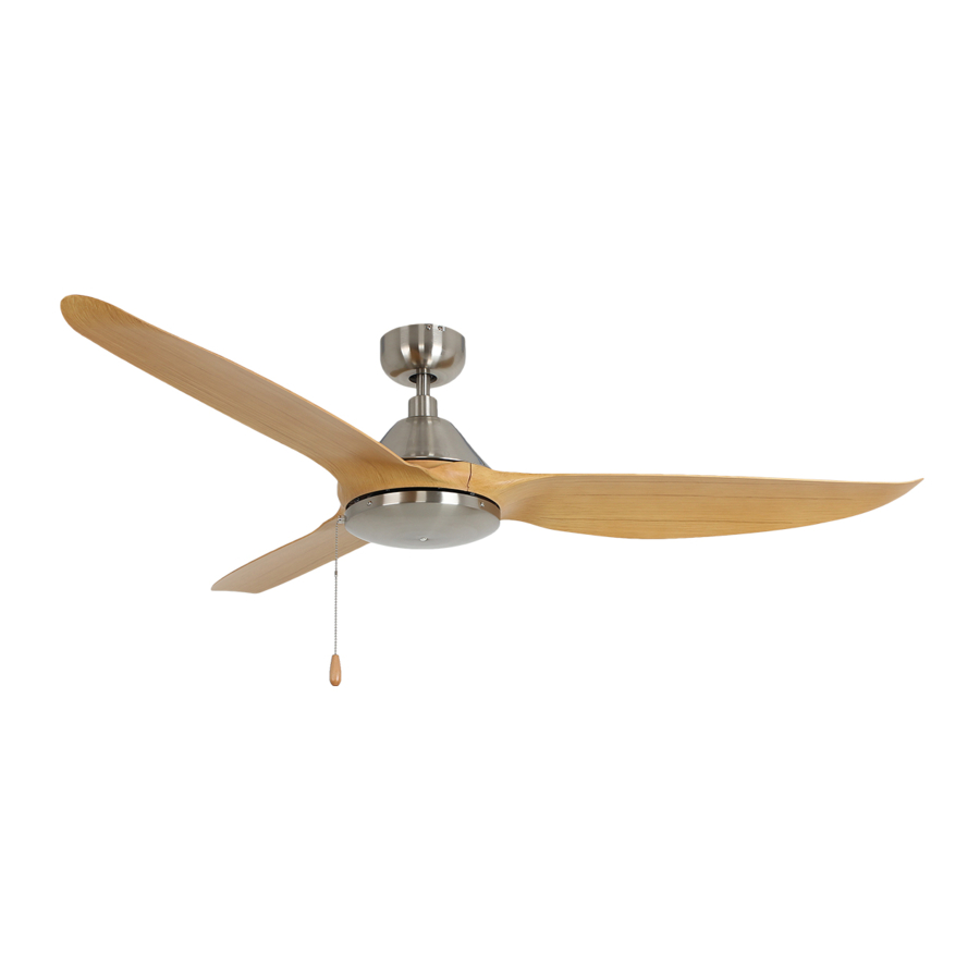
- Page 1 Installation Guide For Models: 1072-PC 1072LED-PC...
-
Page 2: Table Of Contents
SAFETY INFORMATION TOOLS & MATERIALS REQUIRED INSTALLING MOUNTING BRACKET DOWNROD/BALL ASSEMBLY HANGING THE FAN MOTOR ASSEMBLY MAKING ELECTRICAL CONNECTIONS CANOPY ASSEMBLY BLADE INSTALLATION ATTACHING SWITCH HOUSING COVER INSTALLING THE LIGHT KIT OPERATING YOUR FAN REVERSING SWITCH TROUBLESHOOTING... -
Page 3: Safety Information
SAFETY INFORMATION 1. To reduce the risk of electric shock, turn the electricity off at main fuse box or circuit breaker before beginning fan installation or servicing the fan. 2. Read all instructions and safety information carefully before installing your fan and save this manual. -
Page 4: Tools & Materials Required
TOOLS & MATERIALS REQUIRED .Ladder ·Pliers ·Wire Strippers ·Phillips Screwdriver Model#1072-PC 8. Hardware bag included: Parts Quantity Quantity Mounting bracket Wood screws Downrod / ball assembly Hanging bracket screws Ceiling canopy Spring washers Coupling cover Flat washers Fan motor assembly... - Page 5 Model#1072LED-PC 8. Hardware bag included: Parts Quantity Quantity Mounting bracket Wood screws Downrod / ball assembly Hanging bracket screws Ceiling canopy Spring washers Coupling cover Flat washers Fan motor assembly Wire nuts LED light kit Balance kit 1 set Fan blades Pull chain (Wood tassel) Blade screws and flat washers...
-
Page 6: Installing Mounting Bracket
INSTALLING MOUNTING BRACKET Shut the power off at the circuit breaker box before beginning. Warning: Failure to disconnect power supply prior to installation may result in serious injury. For safety and best operating results, installation must be undertaken by qualified electrician. Before installing the fan make sure the outlet box is properly installed to house structure. -
Page 7: Downrod/Ball Assembly
DOWNROD / BALL ASSEMBLY ˙Locate downrod assembly. Loosen ground Blue wire White wire screw on black hanging ball and setscrew to free lock pin, black hanging ball will slide down. Black Wire Green ground wire ˙Remove ground screw and green ground wire. Remove hanging ball from downrod and save all parts. -
Page 8: Making Electrical Connections
MAKING ELECTRICAL CONNECTIONS Warning: All wiring must be in accordance with national and local electrical codes ANSI/NFPA INPUT VOLT.120V 70. If you are unfamiliar with wiring or in doubt, consult a qualified electrician. Follow the steps below to connect the fan GREEN GROUND to your household wiring. -
Page 9: Canopy Assembly
NOTE: Only use an optional wall switch designed for use with ceiling fans. INPUT VOLT.120V If you select to control the motor from a wall LIGHT GREEN GROUND switch, remember the wall switch will only turn your fan ON or OFF. The speed can be adjusted OUTLET BOX IN CEILING by pull chain. -
Page 10: Blade Installation
NOTE: Place the fan blade on the flywheel and align the middle hole on the fan blade with the hole next to a debossed line on the flywheel. ˙Repeat this process to install the other blades to the motor. Model#1072-PC Flat washer Model#1072LED-PC... -
Page 11: Attaching Switch Housing Cover
ATTACHING SWITCH HOUSING COVER Locate 3 screws on switch housing mounting plate, attach the cover to switch housing by using these 3 screws and tighten securely. Model#1072-PC Switch housing... -
Page 12: Installing The Light Kit
INSTALLING THE LIGHT KIT CAUTION: To reduce the risk of electric shock, disconnect the electrical supply circuit to the fan before installing light kit. Connect the 4-pin connector from the LED light kit to the 4-pin connector from motor assembly together carefully. -
Page 13: Operating Your Fan
OPERATING YOUR FAN Connect the WOOD TASSEL to the pull chain located in switch housing. Turn on the power and check the operation of your fan. 3-SPEED PULL CHAIN 1 pull = High Speed 2 pulls = Medium Speed 3 pulls = Low Speed 4 pulls = Fan Off Connect the two WOOD TASSELS to the pull chains located in light kit ( Model #1072LED-PC ). -
Page 14: Reversing Switch
REVERSING SWITCH Your ceiling fan can operate either summer or winter mode. SUMMER Mode: The reverse switch shall be in the “left” (SUMMER) position to make the fan rotate in an anticlockwise direction. The airflow will be directed downwards, for cooling in summer. WINTER Mode: The reverse switch shall be in the “right”... -
Page 15: Troubleshooting
TROUBLESHOOTING WARNING: Failure to disconnect power supply prior to troubleshooting any wiring issues may result in serious injury. Problem Solutions - Check circuit fuses or breakers. Fan will not start. - Check line wire connections to the fan and switch wire connections in the switch housing. Fan sounds noisy. - Page 16 RP-120419...
Need help?
Do you have a question about the 1072-PC and is the answer not in the manual?
Questions and answers