Table of Contents
Advertisement
AUTOMATIC BAR FEEDER
EN
Rel. 0
S/N
This manual is a translation of the original document
MANUAL FOR USE AND MAINTENANCE
KEYBOARD INSTRUCTION MANUAL
SPARE PARTS BOOK
SCHEMATICS
EC CONFORMITY DECLARATION FOR MACHINE
Master 80 UP HyperFlexible
MANUAL FOR USE AND MAINTENANCE
Date 30/09/2014
COMPILER:
Bosi Andrea
ON APPROVAL:
ATTACHMENTS LIST
Cod.3840M05440
Ragazzini Massimo
Advertisement
Table of Contents

Subscribe to Our Youtube Channel
Related Manuals for IEMCA Master 80 UP HyperFlexible


Summary of Contents for IEMCA Master 80 UP HyperFlexible
- Page 1 AUTOMATIC BAR FEEDER ATTACHMENTS LIST MANUAL FOR USE AND MAINTENANCE KEYBOARD INSTRUCTION MANUAL SPARE PARTS BOOK SCHEMATICS EC CONFORMITY DECLARATION FOR MACHINE Master 80 UP HyperFlexible MANUAL FOR USE AND MAINTENANCE Rel. 0 Date 30/09/2014 Cod.3840M05440 COMPILER: Bosi Andrea ON APPROVAL:...
- Page 3 MANUFACTURER: IEMCA division of IGMI S.p.A. ADDRESS: Via Granarolo, 167 - 48018 Faenza (RA) - ITALY Tel. 0546/698000 - Fax. 0546/46338 - 0546/46224 TLX 550879 TYPE OF DOCUMENT: MANUAL FOR USE AND MAINTENANCE PRODUCT: AUTOMATIC BAR FEEDER MODEL: Master 80 UP HyperFlexible IEMCA division of IGMI S.p.A.
-
Page 5: Table Of Contents
ACCESSORIES - FOREWORD ................... 27 2.7.1 Bush holder device - Description ..................27 SAFETY - GENERAL INFORMATION Master 80 UP HyperFlexible ........ 1 GENERAL SAFETY REGULATIONS ................... 2 HANDLING AND INSTALLATION - Safety ................3 ADJUSTMENTS AND SETUP - Safety ................. 3 USE AND OPERATION - Safety ................... - Page 6 INDEX FORESEEABLE MISUSES ....................13 HANDLING AND INSTALLATION Master 80 UP HyperFlexible ........1 PACKAGING ......................... 2 LIFTING .......................... 2 4.2.1 Bar feeder without packaging - Lifting ................3 4.2.2 Bar feeder with pallet - Lifting ..................... 4 4.2.3 Bar feeder with crate - Lifting ..................... 4 INSTALLATION AREA - FEATURES ................
- Page 7 Elevator carriage drive - Adjustment ................20 5.4.3 Elevator carriages - Setup ....................20 USE AND OPERATION Master 80 UP HyperFlexible ............1 CONTROL DESCRIPTION ....................2 KEYBOARD CONTROL DESCRIPTION ................5 MAGAZINE PUSH-BUTTON PANEL - CONTROL DESCRIPTION ........9 LIGHT INDICATOR - SIGNAL DESCRIPTION ..............
- Page 8 INDEX TROUBLES - CAUSES - SOLUTIONS Master 80 UP HyperFlexible ....... 1 GENERAL FAILURES ....................3 ELEVATOR CARRIAGES - FAILURES ................3 FEEDING INTO COLLET – Failures ................4 BAR FEEDING - Failures ....................4 REMNANT MOVEMENT - FAILURES .................. 4 PART REPLACEMENT Master 80 UP HyperFlexible ............
- Page 9 INDEX 11.7 COLLETS FOR 001P BARS ....................10 11.8 COLLET FOR BARS - Table ....................10 11.9 PIPE COLLETS 012-077-377 ....................13 11.10 PIPE COLLETS - Table ....................... 13 11.11 EJECTOR 336 ........................17 11.12 EJECTOR – Guide channels ø<30 - Table ................ 17 11.13 EJECTOR –...
- Page 11 1 - GENERAL INFORMATION Master 80 UP HyperFlexible INDEX WARRANTY CONDITIONS ..................2 PURPOSE OF THE MANUAL ..................3 MANUFACTURER AND BAR FEEDER IDENTIFICATION ..........4 ASSISTANCE REQUEST .................... 5 ATTACHMENT LIST ....................5 1 - Pag. 1 / 1...
-
Page 12: Warranty Conditions
1 - GENERAL INFORMATION Master 80 UP HyperFlexible The operations described in the sections that are preceded by this symbol must be performed by qualified and skilled personnel with specific abilities and precise technical competence only. Any other operation can be performed either by qualified personnel and/or by professional bar feeder operators. -
Page 13: Purpose Of The Manual
INFORMATION: The data included in this publication are only given as an example. IEMCA may apply changes to the model described in this publication at any time for any technical or business reason. Contact IEMCA service department for further information. -
Page 14: Manufacturer And Bar Feeder Identification
1 - GENERAL INFORMATION Master 80 UP HyperFlexible MANUFACTURER AND BAR FEEDER IDENTIFICATION A Manufacturer identification. B EC mark of conformity. C Year of manufacture. D Bar feeder model. E Serial number. G Mains frequency. H Power consumption. M Supply voltage. -
Page 15: Assistance Request
1 - GENERAL INFORMATION Master 80 UP HyperFlexible ASSISTANCE REQUEST Whenever necessary, please apply to one of the centres shown in the "LIST OF THE CUSTOMER SERVICE CENTRES". INFORMATION: when requesting technical assistance for the bar feeder, always specify the data shown on the identification plate. - Page 17 2 - TECHNICAL INFORMATION Master 80 UP HyperFlexible INDEX BAR FEEDER GENERAL DESCRIPTION ............... 2 2.1.1 Bar feeder - Main components .................. 4 2.1.2 Magazine - Main components ..................6 2.1.3 Hydraulic system - Main components ................ 7 2.1.4 Pneumatic system - Main components ............... 8 OPERATING CYCLE - GENERAL DESCRIPTION ............
-
Page 18: Bar Feeder General Description
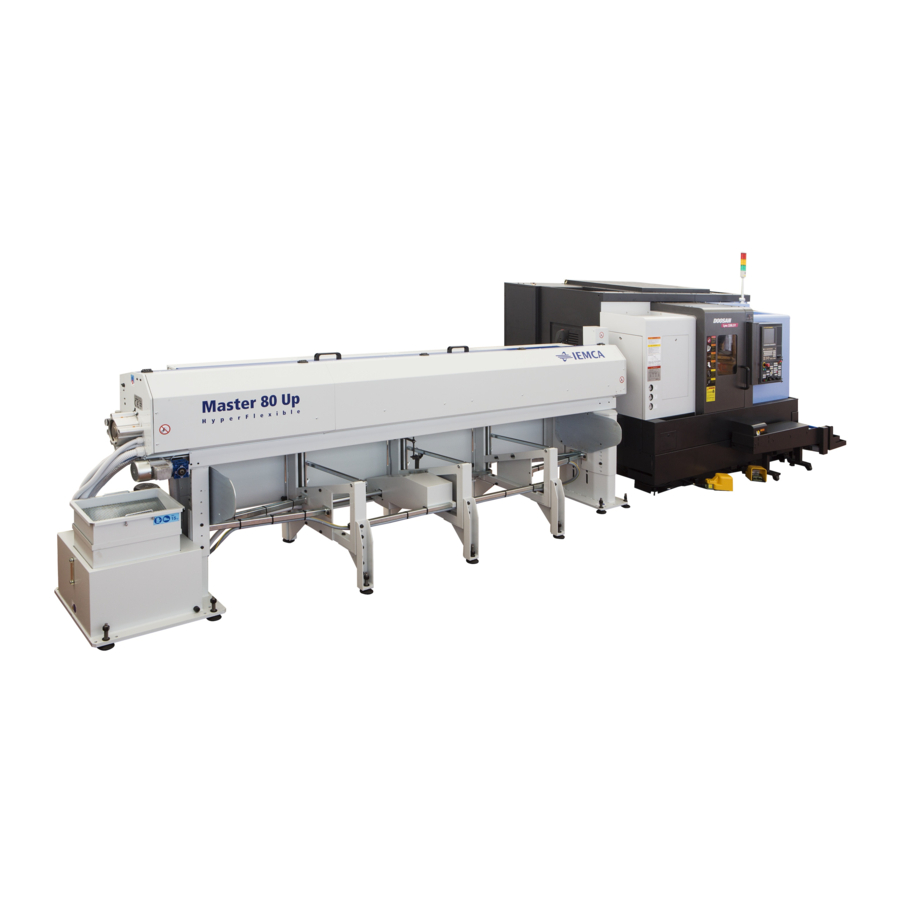
2 - TECHNICAL INFORMATION Master 80 UP HyperFlexible BAR FEEDER GENERAL DESCRIPTION The MASTER 80 HF UP automatic bar feeder is used in the machine-tool industry and in particular for automatic lathe feeding. The operating cycle is controlled by a PLC, integrated in the electrical control panel, which is able to communicate with the lathe control system. - Page 19 2 - TECHNICAL INFORMATION Master 80 UP HyperFlexible The MASTER 80 HF UP bar feeders are available in the following models: MASTER 80 HF UP (standard version) rack magazine MASTER 80r HF UP (reversed version) rack magazine When not otherwise specified, the texts, tables and pictures of this manual refer to the standard version.
-
Page 20: Bar Feeder - Main Components
2 - TECHNICAL INFORMATION Master 80 UP HyperFlexible 2.1.1 Bar feeder - Main components A GUIDE CHANNELS; drive the bar during the machining. B FIRST FEEDING CARRIAGE; moves the bar forwards until the necessary space for the bar pusher introduction has been created. - Page 21 2 - TECHNICAL INFORMATION Master 80 UP HyperFlexible M REMNANT CONVEYOR BELT; carries the bar remnant from the ejection area to the recovery box. N REMNANT CONVEYOR BELT DRIVE; it moves the remnant conveyor belt. P REMNANT RECOVERY BOX; collects the bar remnant.
-
Page 22: Magazine - Main Components
2 - TECHNICAL INFORMATION Master 80 UP HyperFlexible 2.1.2 Magazine - Main components A BAR SUPPORT BRACKET; supports the bars. Thanks to its inclination, the bars lean against the elevator uprights. B ELEVATOR CARRIAGES; move the bars from the magazine to the bar feeder guide channels. -
Page 23: Hydraulic System - Main Components
2 - TECHNICAL INFORMATION Master 80 UP HyperFlexible 2.1.3 Hydraulic system - Main components The oil performs the following cycle: it is forced by pump (2) of tank (1), it flows into the guide channels (4) and bush holder device (5) in order to lubricate the bars during the machining. -
Page 24: Pneumatic System - Main Components
2 - TECHNICAL INFORMATION Master 80 UP HyperFlexible 2.1.4 Pneumatic system - Main components A - PNEUMATIC BAR DROP CONTROL DEVICE UNIT B - FACING CYLINDER C - BUSHING DRIVE UNIT D - PNEUMATIC CLAMP UNIT E - REMNANT DROP UNIT... - Page 25 2 - TECHNICAL INFORMATION Master 80 UP HyperFlexible 2 - Pag. 9 / 9...
-
Page 26: Operating Cycle - General Description
2 - TECHNICAL INFORMATION Master 80 UP HyperFlexible OPERATING CYCLE - GENERAL DESCRIPTION 2.2.1 OPERATING CYCLE The automatic mode controls the movements of the bar feeder according to the sequence described below. The bar pusher (A) makes bar (B) move forwards into the lathe until the bars are finished. - Page 27 2 - TECHNICAL INFORMATION Master 80 UP HyperFlexible The bar pusher (A) and remnant (C) are in their backwards limit stop position. The clamps (D) close and the bar pusher moves backwards; the remnant is removed from the collet. The clamps open, the bar pusher (A) moves forwards and place the remnant on the drop...
- Page 28 2 - TECHNICAL INFORMATION Master 80 UP HyperFlexible The upper guide channels (G) are lifted together with the bar pusher (H), and also the bar drop control levers L are lifted. The elevator carriages (M) lower, the bar (N) drops on the lower guide channels (P) accompanied by the levers (L).
- Page 29 2 - TECHNICAL INFORMATION Master 80 UP HyperFlexible The first feeding carriage (Q) stroke begins. When the first feeding carriage (Q) completes its stroke, the required space for bar pusher introduction has been created. The first feeding carriage performs the return stroke.
- Page 30 2 - TECHNICAL INFORMATION Master 80 UP HyperFlexible The upper guide channels (N) close; the bar pusher (M) is positioned along the spindle axis. The clamps (D) close, the bar pusher (A) moves forwards; the bar (N) is inserted into the bar pusher collet.
-
Page 31: Magazine - Operating Cycle
2 - TECHNICAL INFORMATION Master 80 UP HyperFlexible 2.2.2 Magazine - Operating cycle The automatic mode controls the magazine movements according to the sequence described below. The elevator carriages (A) are in the highest position and support bar (B), which is ready to be unloaded in the guide channels (C). -
Page 32: Safety Devices - Position And Description
2 - TECHNICAL INFORMATION Master 80 UP HyperFlexible SAFETY DEVICES - POSITION AND DESCRIPTION 2.3.1 Bar feeder - Safety devices A EMERGENCY BUTTON; when pressed, all bar feeder and lathe functions are stopped in an emergency condition. B INTERLOCKED SLIDING GUARD; linked to microswitch B1. When the guard is opened, the bar feeder and lathe functions are suspended. -
Page 33: Safety Plates - Location And Description
2 - TECHNICAL INFORMATION Master 80 UP HyperFlexible SAFETY PLATES - LOCATION AND DESCRIPTION A Crushing danger of the upper limbs. B Warning; danger of electric contact. C Pay attention to the moving parts. D Warning; it is forbidden to climb on the machine. -
Page 34: Version Description
2 - TECHNICAL INFORMATION Master 80 UP HyperFlexible VERSION DESCRIPTION Bar length Maximum Minimum length Intermediate Model Version length mm (ft) - B feelers mm (ft) - A 3300 (10,8) 2000 (6,5) MASTER 80 UP 3800 (12,4) 2500 (8,2) HyperFlex... - Page 35 2 - TECHNICAL INFORMATION Master 80 UP HyperFlexible Max. bar pusher extension A –Max. Model Version Version extension(mm) 1045 33-38-43 1295 MASTER 80 UP 33-38-43-63 1545 HyperFlex 38-43 1795 38-43 2045 A01PF_MUM_02_05_04 Revolving tip Nipple 2 - Pag. 19 / 19...
-
Page 36: Technical Data
2 - TECHNICAL INFORMATION Master 80 UP HyperFlexible TECHNICAL DATA 2 - Pag. 20 / 20... - Page 37 2 - TECHNICAL INFORMATION Master 80 UP HyperFlexible Overall dimensions Model Version A (mm) B (mm) C (mm) D (mm) E (mm) 4330 3640 MASTER 80 UP 4830 4140 1110 1250 HyperFlex 5330 4640 1360 2 - Pag. 21 / 21...
- Page 38 2 - TECHNICAL INFORMATION Master 80 UP HyperFlexible General technical data MASTER 80 UP HyperFlex Ø Min 8 mm Ø Max 80 mm Round bar size (5/16") (3") Min7 mm Max65 mm Hexagonal bar size (key socket) (5/16") (2" 1/4)
- Page 39 2 - TECHNICAL INFORMATION Master 80 UP HyperFlexible Working axis height (mm) (mm) Model Screw position High base Low base 1221÷1255 906÷940 1256÷1290 941÷975 1391÷1325 976÷1010 1326÷1360 1011÷1045 MASTER 80 UP 1361÷1395 1046÷1080 HyperFlex 1396÷1430 1081÷1115 1431÷1465 1116÷1150 1466÷1500 1151÷1185 1501÷1535...
- Page 40 2 - TECHNICAL INFORMATION Master 80 UP HyperFlexible Guide channel, bar pusher, bar and pipe diameter. Guide Bar diameter(mm) Bar pusher Pipe channel Minimum Maximum Model diameter(m diameter(m diameter(mm m) (*) (**) 15/20 (**) 15/20 MASTER 80 UP HyperFlex (**) 15/20...
- Page 41 2 - TECHNICAL INFORMATION Master 80 UP HyperFlexible Guide channel lubricating oils. ISO/UNI Brand Name rating ENERGOL CS 150 Agip Acer 150 Api Cis 150 Aral Aral Degol Tu 150 Castrol Magna 150 Chevron Circulating Oil 150 Movixa 150 Esso...
-
Page 42: Noise Levels
2 - TECHNICAL INFORMATION Master 80 UP HyperFlexible 2.6.1 Noise levels The bar feeder does not cause acoustic noise. The noise occurs when the lathe, to which the bar feeder is connected, is working and the bar is rotating into the bar feeder guide channels. -
Page 43: Accessories - Foreword
2 - TECHNICAL INFORMATION Master 80 UP HyperFlexible ACCESSORIES - FOREWORD To increase the bar feeder performance and flexibility, it may be provided with the accessory described below. 2.7.1 Bush holder device - Description It is applied to the front part of the bar feeder. Its... - Page 45 3 - SAFETY - GENERAL INFORMATION Master 80 UP HyperFlexible INDEX GENERAL SAFETY REGULATIONS ................2 HANDLING AND INSTALLATION - Safety ..............3 ADJUSTMENTS AND SETUP - Safety ................3 USE AND OPERATION - Safety .................. 4 BAR FEEDER MAINTENANCE - Safety ................ 5 EC DECLARATION OF CONFORMITY .................
-
Page 46: General Safety Regulations
Strictly comply with the health and safety regulations at work issued by the relevant authorities in each country. • IEMCA declines any liability for injury to persons or damage to property if the relevant safety regulations are disregarded. 3 - Pag. 2 / 2... -
Page 47: Handling And Installation - Safety
3 - SAFETY - GENERAL INFORMATION Master 80 UP HyperFlexible HANDLING AND INSTALLATION - Safety • The bar feeder must be handled using suitable means and methods only. • Do not stand or transit underneath a suspended load, or within the range of action of the crane, lift truck or other suitable lifting and transport means. -
Page 48: Use And Operation - Safety
3 - SAFETY - GENERAL INFORMATION Master 80 UP HyperFlexible USE AND OPERATION - Safety • The working area around the bar feeder must always be kept clean and uncluttered so as to allow immediate access to the emergency devices and to perform the bar loading without creating obstructions or danger. -
Page 49: Bar Feeder Maintenance - Safety
• Avoid environmental pollution. • Use original IEMCA spare parts only. • Considering that oil and polyurethane material is used, the disposal of the guide channels will be performed according to the regulations in force in the installation country. -
Page 50: Ec Declaration Of Conformity
EC DECLARATION OF CONFORMITY EC CONFORMITY DECLARATION (2006/42/ EC Regulation, EnclosureII, Part A) Mr TOMASO TAROZZI, acting as MANAGING IEMCA with legal office and delegated by the company I G M I S.p.A. DIVISIONE IEMCA with legal office and establishment in Via Granarolo, 167 –... -
Page 51: General Description Of Supply
Should the bar feeder be used together with machine tools that do not have the CE marking, Iemca reminds to their clients that they should assess if the device is in compliance with Directive 2009/104/EC and subsequent amendments even after installing the bar feeder. -
Page 52: Residual Risks
3 - SAFETY - GENERAL INFORMATION Master 80 UP HyperFlexible RESIDUAL RISKS • The following residual risks exist: PNEUMATIC POWER Presence of pneumatic energy in the supply system to the machine actuators. Here are some examples of the warnings referenced above: Before doing regular maintenance or any other service on the machine pneumatic actuators it is essential to stop the pneumatic energy supply by disconnecting the supply hose (see chapter 4). - Page 53 3 - SAFETY - GENERAL INFORMATION Master 80 UP HyperFlexible 1)Bush replacement or maintenance work inside the bushing holding equipment should only be performed after switching the bar feeder off. 2)With the bar feeder in automatic mode, there is a potential crushing risk if you reach your hands and arms into the guide channel area (bar pusher movement).
- Page 54 3 - SAFETY - GENERAL INFORMATION Master 80 UP HyperFlexible BAR FEEDER FASTENING IN AN UNSTEADY EQUILIBRIUM 1) If during installation the floor proves not to be level, the authorized technician will level out and align the bar feeder using the levelling screws of the fastening plates in the outer part of the bar feeder and in the anti-vibration plugs in the inner part.
- Page 55 3 - SAFETY - GENERAL INFORMATION Master 80 UP HyperFlexible FIXED GUARDS If you have removed some fixed guards in order to be able to perform maintenance on the bar feeder, put them back in place and secure them soon after completing your work.
- Page 56 3 - SAFETY - GENERAL INFORMATION Master 80 UP HyperFlexible 1)The colour loses intensity. 2)Other pieces of equipment or panels placed too close to the warning lamps on the bar feeder. THERE ARE CIRCUITS NOT INTERRUPTED BY THE DISCONNECTING DEVICE There is danger caused by voltages from the lathe signals that are not interrupted by disconnectors in the bar feeder.
-
Page 57: Foreseeable Misuses
3 - SAFETY - GENERAL INFORMATION Master 80 UP HyperFlexible FORESEEABLE MISUSES • Do not tamper with the machine's safety devices (for example, the safety microswitches of the openable guard to access the bar magazine) • Do not use the lubrication pump for other purposes (for example, to pour different liquids) •... - Page 59 4 - HANDLING AND INSTALLATION Master 80 UP HyperFlexible INDEX PACKAGING ......................2 LIFTING ......................2 4.2.1 Bar feeder without packaging - Lifting ............... 3 4.2.2 Bar feeder with pallet - Lifting ................... 4 4.2.3 Bar feeder with crate - Lifting ................... 4 INSTALLATION AREA - FEATURES ..............
-
Page 60: Packaging
4 - HANDLING AND INSTALLATION Master 80 UP HyperFlexible PACKAGING There are three possible bar feeder packaging: A WITHOUT PACKAGING. B WITH PALLET: the bar feeder is placed on a pallet and wrapped with protective film. C WITH CRATE: the bar feeder is contained in a crate and wrapped with protective film. -
Page 61: Bar Feeder Without Packaging - Lifting
4 - HANDLING AND INSTALLATION Master 80 UP HyperFlexible 4.2.1 Bar feeder without packaging - Lifting • Fit the two lifting brackets (A) (at a distance of 2,710 mm from each other with magazine L=33). • Use a hook lifting device of adequate capacity. -
Page 62: Bar Feeder With Pallet - Lifting
4 - HANDLING AND INSTALLATION Master 80 UP HyperFlexible 4.2.2 Bar feeder with pallet - Lifting Use a hook type lifting device of suitable load capacity. 4.2.3 Bar feeder with crate - Lifting Use a hook type lifting device of suitable load capacity. -
Page 63: Installation Area - Features
4 - HANDLING AND INSTALLATION Master 80 UP HyperFlexible INSTALLATION AREA - FEATURES The floor should be stable and levelled to guarantee good fastening to the ground. Provide an area of suitable dimensions according to the type of bar feeder used. -
Page 64: Backing Plates And Support Feet - Installation
4 - HANDLING AND INSTALLATION Master 80 UP HyperFlexible 4.4.1 Backing plates and support feet - Installation • Position the bar feeder next to the lathe. • Lift it and install the plates in the positions shown in the figure. -
Page 65: Height - Adjustment
4 - HANDLING AND INSTALLATION Master 80 UP HyperFlexible 4.4.2 Height - Adjustment The bar feeder is normally supplied with the working axis height adjusted to the lathe height. However, if an adjustment is needed, proceed as follows: • stretch the lifting chains and remove screws (A) in the front and rear bases;... - Page 66 4 - HANDLING AND INSTALLATION Master 80 UP HyperFlexible • tighten screws (A) and fit brackets (B) again. 4 - Pag. 8 / 8...
-
Page 67: Preliminary Positioning
4 - HANDLING AND INSTALLATION Master 80 UP HyperFlexible 4.4.3 Preliminary positioning • Place the bar feeder behind the lathe, considering the fixed and moving dimensions of both machines. The coupling distance (B) should not exceed the bar pusher maximum extension (A). -
Page 68: Front Nose - Installation
4 - HANDLING AND INSTALLATION Master 80 UP HyperFlexible • Roughly adjust the height of the working axis and the alignment with the lathe by turning the screws of the support feet. 4.4.4 Front nose - Installation • Install the front nose (A) in the bush holder device. -
Page 69: Levelling And Alignment
4 - HANDLING AND INSTALLATION Master 80 UP HyperFlexible 4.4.5 Levelling and alignment FOREWORD The alignment between the bar feeder and lathe is the most critical phase; therefore, this operation should be carried out with the greatest accuracy by experienced personnel. - Page 70 4 - HANDLING AND INSTALLATION Master 80 UP HyperFlexible • Press to select the semiautomatic function. Press several times until the upper guide channels open; "GUIDE CHANNEL FULL OPENING" should appear on the display. • Remove the first and last lower guide channels by pressing on the pressure couplings.
- Page 71 4 - HANDLING AND INSTALLATION Master 80 UP HyperFlexible LEVELLING • Rest the special shelf on the supports. • Check the levelling by positioning the level crosswise and lengthwise. • Carry out the required corrections by turning the support feet screws.
- Page 72 4 - HANDLING AND INSTALLATION Master 80 UP HyperFlexible ALIGNMENT The alignment is obtained by fitting a nylon thread (ø 1 mm) between the lathe collet and the first feeding carriage, proceeding as follows: • place a drilled bush (A) in the lathe collet;...
- Page 73 4 - HANDLING AND INSTALLATION Master 80 UP HyperFlexible POSITIONING ADJUSTMENTS After checking the alignment of the bar feeder with either the thread or the bar, any required corrections should be carried out. Adjust the height by turning the support feet screws.
-
Page 74: Bar Feeder Fastening
4 - HANDLING AND INSTALLATION Master 80 UP HyperFlexible 4.4.6 Bar feeder fastening WARNING - CAUTION: failure to perform or a wrong bar feeder fastening to the ground may be the major cause of a bad operation of the bar feeder and of its consequent damage. -
Page 75: Lubrication Oil - Filling
4 - HANDLING AND INSTALLATION Master 80 UP HyperFlexible LUBRICATION OIL - FILLING WARNING - CAUTION: wear personal protections according to the regulations in force. • Remove cover (A). • Pour the oil directly into the tank and check the level through the relevant indicator (B). -
Page 76: Pneumatic Device Layout
4 - HANDLING AND INSTALLATION Master 80 UP HyperFlexible PNEUMATIC DEVICE LAYOUT ABBREVIATION DESCRIPTION FUNCTION Cylinder Enables the clamp opening and closing Enables the guide channel downstroke for Cylinder the remnant drop Cylinder Enables the guide channel locking Enables the guide channel upstroke and... - Page 77 4 - HANDLING AND INSTALLATION Master 80 UP HyperFlexible ABBREVIATION DESCRIPTION FUNCTION Bar drop control device solenoid Pos.1 Bar drop control devices upstroke valve Bar drop control device solenoid Bar drop control devices Pos.2 valve downstroke Pos.3 Guide channel control solenoid valve Guide channel closing Pos.4...
- Page 78 4 - HANDLING AND INSTALLATION Master 80 UP HyperFlexible INFORMATION: the solenoid valves from position n?9 to position n?14 are used according to the bar feeder configuration. 4 - Pag. 20 / 20...
-
Page 79: Pneumatic Connection
4 - HANDLING AND INSTALLATION Master 80 UP HyperFlexible 4.7.1 PNEUMATIC CONNECTION • Connect pipe H of the pneumatic network as shown in the figure. WARNING - CAUTION: adjust pressure follow instruction manual. 4.7.2 BAR FEEDER HANDLING WITHOUT POWER SUPPLY... -
Page 80: Software Parameterization
4 - HANDLING AND INSTALLATION Master 80 UP HyperFlexible SOFTWARE PARAMETERIZATION The bar feeder software should be correctly parameterized according to the working needs and the lathe type. For further information on how to carry out this operation, check the "Keyboard instruction manual". - Page 81 5 - ADJUSTMENT AND SETUP Master 80 UP HyperFlexible INDEX ADJUSTMENT AND SETUP - FOREWORD ............2 GENERAL ADJUSTMENTS - FOREWORD .............. 2 5.2.1 Feeding chain - Adjustment ..................2 5.2.2 Remnant conveyor belt - Adjustment ................ 4 5.2.3 Elevator carriage chains - Adjustment ............... 4 BAR FEEDER SETUP ..................
-
Page 82: Adjustment And Setup - Foreword
5 - ADJUSTMENT AND SETUP Master 80 UP HyperFlexible ADJUSTMENT AND SETUP - FOREWORD DANGER - WARNING: do not perform any adjustment when the bar feeder is running unless expressly requested in the manual. This bar feeder requires, besides the ordinary adjustments necessary during its life, also adjustments depending on the bar dimensions and the magazine type. - Page 83 5 - ADJUSTMENT AND SETUP Master 80 UP HyperFlexible • Loosen both screws (A) and adjust the chain tension by turning screw (B). • Restore the bar feeder initial operating conditions. WARNING-CAUTION Perform the chain adjustment by means of a torque wrench, tighten screw (B) by setting the torque to 4N/meter, then tighten both fixing screws (A).
-
Page 84: Remnant Conveyor Belt - Adjustment
5 - ADJUSTMENT AND SETUP Master 80 UP HyperFlexible 5.2.2 Remnant conveyor belt - Adjustment INFORMATION: Check and if necessary adjust the belt tension after the first 20-30 working hours of the bar feeder. • Move the bar feeder body backwards. -
Page 85: Bar Feeder Setup
5 - ADJUSTMENT AND SETUP Master 80 UP HyperFlexible BAR FEEDER SETUP If the diameter of the bars to be machined changes, it may be necessary to perform adjustments on the machine. Refer to the "Guide channel, bar pusher, bar and pipe diameter" table in section 2. - Page 86 5 - ADJUSTMENT AND SETUP Master 80 UP HyperFlexible • Remove the bar pusher from both supports. For the bar pusher replacement refer to the next section. • Disassemble the first feeding pin (B) from the flag (A). 5 - Pag. 6 / 6...
- Page 87 5 - ADJUSTMENT AND SETUP Master 80 UP HyperFlexible • Remove the lower and upper guide channels. • Replace the bar pusher supports with those of "new" diameter. 5 - Pag. 7 / 7...
- Page 88 5 - ADJUSTMENT AND SETUP Master 80 UP HyperFlexible • Remove the screw (E), lower the A01PF_MUM_05_03_00 rear lever and move the bar feeder body backwards. WARNING - CAUTION: before performing this operation, power the lathe off. • Remove the oil recovery device (C) and sleeve (D).
- Page 89 5 - ADJUSTMENT AND SETUP Master 80 UP HyperFlexible • Remove the lathe spindle liner if required and install a suitable liner for the "new" diameter, if necessary. • Assemble sleeve (D) of the "new" diameter and the oil recovery (C).
- Page 90 5 - ADJUSTMENT AND SETUP Master 80 UP HyperFlexible • Assemble the lower and upper guide channels of the "new" diameter. INFORMATION: Warning; follow the correct assembly direction of the guide channels. WARNING - CAUTION: Use the specific screws allowing to lock the guide channels.
- Page 91 5 - ADJUSTMENT AND SETUP Master 80 UP HyperFlexible • Choose an appropriate collet for the bar diameter and profile; see "GUIDE CHANNELS-BAR PUSHER- REVOLVING TIPS" and "COLLETS" section. INFORMATION: contact IEMCA service department for further information. WARNING - CAUTION: At every collet change (model 381p, 381p..011,...
- Page 92 5 - ADJUSTMENT AND SETUP Master 80 UP HyperFlexible WARNING - CAUTION: the collet external diameter should be at least 0.5 mm smaller than the bar pusher external diameter. • Install the collet in the bar pusher and make sure...
- Page 93 5 - ADJUSTMENT AND SETUP Master 80 UP HyperFlexible • Properly position the bar pusher in the radial direction so that in the next phase of the upper guide channel closing, the coupling between the bar pusher and the first feeding carriage (B) occurs correctly.
-
Page 94: Bar Pusher Replacement Procedure
5 - ADJUSTMENT AND SETUP Master 80 UP HyperFlexible 5.3.2 BAR PUSHER REPLACEMENT PROCEDURE WARNING - CAUTION Never perform the following procedure when a bar is detected in the bar pusher collet! The replacement of the bar pusher, for a working cycle change or maintenance, may be... - Page 95 5 - ADJUSTMENT AND SETUP Master 80 UP HyperFlexible Close the bar feeder guard, reset the start button [pupa_boss _avvio-1], enter manual mode and, by pressing , move the bar pusher forwards until the clamp position is exceeded of at least 200 mm.
-
Page 96: Remnant Passage Door Spring - Adjustment
5 - ADJUSTMENT AND SETUP Master 80 UP HyperFlexible 5.3.3 Remnant passage door spring - Adjustment The remnant passage door is kept closed by a spring. The remnant passage has to win the spring resistance, so that the door may intercept the detection sensor. -
Page 97: Remnant Drop Chute - Enabling
5 - ADJUSTMENT AND SETUP Master 80 UP HyperFlexible 5.3.4 REMNANT DROP CHUTE – ENABLING If a remnant does not drop onto the remnant conveyor belt after the guide drop (T), parameter 45 can be enabled (see description in the instruction manual) so that the guide starts vibrating and the remnant drops. -
Page 98: Magazine Setup
5 - ADJUSTMENT AND SETUP Master 80 UP HyperFlexible MAGAZINE SETUP 5.4.1 Bar supporting bracket - Setup • Adjust the inclination of the bar supporting bracket. • Move the supporting bracket upwards. 5 - Pag. 18 / 18... - Page 99 5 - ADJUSTMENT AND SETUP Master 80 UP HyperFlexible • Remove the bracket crosswise from left to right. • Move the supporting bracket downwards and reposition the pin by moving it crosswise from left to right. 5 - Pag. 19 / 19...
- Page 100 5 - ADJUSTMENT AND SETUP Master 80 UP HyperFlexible • Attach the bracket to the hook in the new position. BAR CONTAINMENT BRACKET (OPTIONAL) This device aligns the bars having a smaller diameter than 12 mm, so as to avoid that they may overlap.
-
Page 101: Elevator Carriage Drive - Adjustment
5 - ADJUSTMENT AND SETUP Master 80 UP HyperFlexible 5.4.2 Elevator carriage drive - Adjustment The safety joint has to be adjusted so that the bar is lifted and, at the same time, the motor drive is deactivated when the bar cannot be lifted for whatever reason. - Page 103 6 - USE AND OPERATION Master 80 UP HyperFlexible INDEX CONTROL DESCRIPTION ..................2 KEYBOARD CONTROL DESCRIPTION ................. 5 MAGAZINE PUSH-BUTTON PANEL - CONTROL DESCRIPTION ........9 LIGHT INDICATOR - SIGNAL DESCRIPTION ............10 BAR FEEDER TOOLING ................... 11 BARS TO BE MACHINED - FEATURES AND PREPARATION ........11 6.6.1...
-
Page 104: Control Description
6 - USE AND OPERATION Master 80 UP HyperFlexible CONTROL DESCRIPTION INFORMATION: From the hand-held keyboard it is possible to automatically start the bar feeder, even when the Lathe ‘MAN/AUT' signal is in Manual mode. INFORMATION: When the bar feeder is in Automatic mode, the bar feeding is possible only when the Lathe "MAN/AUT"... - Page 105 6 - USE AND OPERATION Master 80 UP HyperFlexible The figure indicates the positions of both the electrical and handheld keyboard "1" controls. 2 MAIN SWITCH: turns the power supply on and off. Position 0 (OFF) the machine is not powered.
- Page 106 6 - USE AND OPERATION Master 80 UP HyperFlexible 6 - Pag. 4 / 4...
-
Page 107: Keyboard Control Description
6 - USE AND OPERATION Master 80 UP HyperFlexible KEYBOARD CONTROL DESCRIPTION 1 It stops the bar feeder: manually release the push-button in order to restart. 2 Start buttons: opposite buttons enabling the keys for some functions. Press both buttons and simultaneously the button corresponding to the desired function. - Page 108 6 - USE AND OPERATION Master 80 UP HyperFlexible 13 Selects the keyboard modes: with LED off ; selects the "message display" mode. with LED on ; selects the "parameter display" mode. 14 Multifunction Selects the next parameter Moves the selection cursor rightwards.
- Page 109 6 - USE AND OPERATION Master 80 UP HyperFlexible 22 Multifunction Sets the numerical value. Moves the bar pusher at a low speed. 23 Multifunction Sets the font. Moves the bar pusher at a high speed. 24 Sets the comma.
- Page 110 6 - USE AND OPERATION Master 80 UP HyperFlexible 28 Multifunction Sets the numerical value. Recalls the main menu (MAIN MENU). 29 Sets the numerical value. 30 Multifunction Sets the numerical value. Moves the bar pusher at a low speed.
-
Page 111: Magazine Push-Button Panel - Control Description
6 - USE AND OPERATION Master 80 UP HyperFlexible MAGAZINE PUSH-BUTTON PANEL - CONTROL DESCRIPTION MASTER 880 P 1 Emergency button for stopping the bar feeder; it will be possible to start it again only after the button has been manually released. -
Page 112: Light Indicator - Signal Description
6 - USE AND OPERATION Master 80 UP HyperFlexible LIGHT INDICATOR - SIGNAL DESCRIPTION BLINKING ORANGE LIGHT; indicates that, with the bar feeder in automatic mode, the magazine is in manual mode. BLINKING ORANGE LIGHT; indicates that the magazine is open. (OPTIONAL) FIXED GREEN LIGHT;... -
Page 113: Bar Feeder Tooling
6 - USE AND OPERATION Master 80 UP HyperFlexible BAR FEEDER TOOLING This is a list of all the bar feeder tooling phases, assuming that the bar feeder is started for the first time. • Perform the bar feeder setup according to the bar to be machined. - Page 114 6 - USE AND OPERATION Master 80 UP HyperFlexible SOLID BARS Make sure that there is not too much rag on the front end, which might hinder from entering the lathe collet. The bar rear end must be chamfered as indicated in the figure.
-
Page 115: Bar Straightness - Measurement
6 - USE AND OPERATION Master 80 UP HyperFlexible 6.6.1 BAR STRAIGHTNESS - Measurement The bar vibrations are partially due to the state of the bar itself: if the bar is not perfectly straight, it can cause vibrations. Round bars... - Page 116 6 - USE AND OPERATION Master 80 UP HyperFlexible Hexagonal, square and section bars With shaped bars, insert some bushes on the bar to be controlled. Position 2 bushes on both V-supports. In that case, the measurement can be carried out as shown in the figure.
-
Page 117: Bar Magazine - Loading
6 - USE AND OPERATION Master 80 UP HyperFlexible BAR MAGAZINE - LOADING WARNING - CAUTION: do not manually lift weights exceeding those foreseen applicable regulations in force; ask for help, if necessary. WARNING - CAUTION: wear personal protections according to the regulations in force. - Page 118 6 - USE AND OPERATION Master 80 UP HyperFlexible • Rotate the selector switch (A) from 0 to 1 magazine in automatic mode. 6.7.1 Empty magazine (OPTIONAL) Sensor (B) detects the presence of the bar in the magazine, the orange light blinks to signal that the magazine is empty (see section 6.4).
-
Page 119: Automatic Cycle Start
6 - USE AND OPERATION Master 80 UP HyperFlexible AUTOMATIC CYCLE START • Power on the lathe. • Turn the main switch to position I (ON). • Press to start the bar feeder. • Press to select the manual mode. -
Page 120: Bar Loading - Procedure
6 - USE AND OPERATION Master 80 UP HyperFlexible BAR LOADING - PROCEDURE Press to select Press Press the “SEMIAUTOMATIC” (phase “BAR PUSHER (phase “ CLAMP function RETURN”) CLOSING ”) Press Press Press (phase “ DROP REMNANT (phase “ CLAMP OPENING (phase “... - Page 121 6 - USE AND OPERATION Master 80 UP HyperFlexible Press Press to cause the bar to drop (Phase “ BAR LOADING ”) SEMIAUTOMATIC from the magazine and procedure appoggiare agli accompagnatori Press Press Press (Phase “ BAR FIRST (Phase “ CARRIAGE (Phase “...
- Page 122 6 - USE AND OPERATION Master 80 UP HyperFlexible Press Push to cause the bar to drop MANUAL to raise the bar drop control from the magazine and device appoggiare agli Procedure (Push accompagnatori Push (for about 2 secs) to activate AUTOMATIC mode 6 - Pag.
-
Page 123: Lubricating Oil - Flow Adjustment
6 - USE AND OPERATION Master 80 UP HyperFlexible 6.10 LUBRICATING OIL - FLOW ADJUSTMENT The oil flow in the guide channels and bush holder device is automatically controlled during the bar feeder automatic cycle. The pump is started when the bar feeder has... -
Page 124: Cycle Performing Mode In The "Step-By-Step" Function
6 - USE AND OPERATION Master 80 UP HyperFlexible 6.12 CYCLE PERFORMING MODE IN THE "STEP-BY-STEP" FUNCTION FOREWORD This mode may be used for many reasons, as for instance: • to check a complete bar change cycle; • to check the bar feeder mechanics;... - Page 125 7 - BAR FEEDER MAINTENANCE Master 80 UP HyperFlexible INDEX MAINTENANCE – GENERAL RULES ..............2 SCHEDULED MAINTENANCE ................3 7.2.1 Lubricating oil - Level check ..................4 7.2.2 Lubricating oil - Change .................... 5 7.2.3 Oil filter - Cleaning ....................6 7.2.4...
-
Page 126: Maintenance - General Rules
7 - BAR FEEDER MAINTENANCE Master 80 UP HyperFlexible MAINTENANCE – GENERAL RULES DANGER - WARNING: carry out the cleaning and maintenance operations when the bar feeder is off. Regular cleaning and maintenance are essential to ensure a correct operation and a long bar feeder service life. -
Page 127: Scheduled Maintenance
7 - BAR FEEDER MAINTENANCE Master 80 UP HyperFlexible SCHEDULED MAINTENANCE Scheduled maintenance 7 - Pag. 3 / 3... -
Page 128: Lubricating Oil - Level Check
7 - BAR FEEDER MAINTENANCE Master 80 UP HyperFlexible 7.2.1 Lubricating oil - Level check WARNING - CAUTION: wear personal protections according to the regulations in force. • Wait until the bar feeder has been off for at least 6 hours. -
Page 129: Lubricating Oil - Change
7 - BAR FEEDER MAINTENANCE Master 80 UP HyperFlexible 7.2.2 Lubricating oil - Change WARNING - CAUTION: wear personal protections according to the regulations in force. INFORMATION: store drain oil in special containers to be delivered to companies specialised in pollutant disposal and storage. -
Page 130: Oil Filter - Cleaning
7 - BAR FEEDER MAINTENANCE Master 80 UP HyperFlexible 7.2.3 Oil filter - Cleaning WARNING - CAUTION: wear personal protections according to the regulations in force. • Wait until the bar feeder has been off for at least 6 hours. -
Page 131: Air Filter Unit - Check
7 - BAR FEEDER MAINTENANCE Master 80 UP HyperFlexible 7.2.4 Air filter unit - Check FILTER (A) • Make sure that cup (B) is not full of condensate. Drain the condensate by means of valve (C), if necessary. • The filter is equipped with a control pressure switch, set to a pressure of 4.5 bar. -
Page 132: Lubrication Point Diagram
7 - BAR FEEDER MAINTENANCE Master 80 UP HyperFlexible LUBRICATION POINT DIAGRAM 7 - Pag. 8 / 8... - Page 133 8 - TROUBLES - CAUSES - SOLUTIONS Master 80 UP HyperFlexible INDEX GENERAL FAILURES ..................3 ELEVATOR CARRIAGES - FAILURES ................3 FEEDING INTO COLLET – Failures ..............4 BAR FEEDING - Failures ..................4 REMNANT MOVEMENT - FAILURES ................4...
- Page 134 8 - TROUBLES - CAUSES - SOLUTIONS Master 80 UP HyperFlexible 8 - Pag. 2 / 2...
-
Page 135: General Failures
8 - TROUBLES - CAUSES - SOLUTIONS Master 80 UP HyperFlexible GENERAL FAILURES TROUBLES CAUSES SOLUTIONS No power. Check the electrical connection. Open guard. Close the guard. The bar feeder cannot start Emergency systems on. Disconnect the emergency devices. Motor thermal circuit breaker Reset the thermal circuit breaker burnt. -
Page 136: Feeding Into Collet - Failures
8 - TROUBLES - CAUSES - SOLUTIONS Master 80 UP HyperFlexible FEEDING INTO COLLET – Failures TROUBLES CAUSES SOLUTIONS Collet diameter not suitable Change collet for bar diameter Bar fails to enter collet Excessive rag on bar rear end Trim rag before feeding... - Page 137 9 - PART REPLACEMENT Master 80 UP HyperFlexible INDEX FEEDING CHAIN – REPLACEMENT ..............2 ELEVATOR CARRIAGE DRIVE SAFETY JOINT - REPLACEMENT ......2 REMNANT CONVEYOR BELT - REPLACEMENT ............. 3 PLC BATTERY – REPLACEMENT ................4 RECOMMENDED SPARE PARTS ................
-
Page 138: Feeding Chain - Replacement
9 - PART REPLACEMENT Master 80 UP HyperFlexible FEEDING CHAIN – REPLACEMENT The replacement of the feeding chain is a very complex operation; contact IEMCA service department. ELEVATOR CARRIAGE DRIVE SAFETY JOINT - REPLACEMENT • Slacken the drive chain: •... -
Page 139: Remnant Conveyor Belt - Replacement
9 - PART REPLACEMENT Master 80 UP HyperFlexible REMNANT CONVEYOR BELT - REPLACEMENT • Slacken the belt. • Lift the belt. WARNING - CAUTION: During this manoeuvre be careful not to damage the remnant passage door. • Cut the worn belt so that it can be removed from its seat. -
Page 140: Plc Battery - Replacement
9 - PART REPLACEMENT Master 80 UP HyperFlexible PLC BATTERY – REPLACEMENT Replace the battery every year, or when the following message is displayed: "PLC battery exhausted" INFORMATION: PLC battery exhausted when this message is displayed, the battery should replaced... -
Page 141: Recommended Spare Parts
9 - PART REPLACEMENT Master 80 UP HyperFlexible RECOMMENDED SPARE PARTS The parts subject to wear or easily breakable parts are listed below (for a period of two years, normal use of the bar feeder). Model Code Name Features Notes... - Page 143 10 - GUIDE CHANNELS-BAR PUSHER-REVOLVING TIPSMaster 80 UP HyperFlexible INDEX 10.1 GUIDE CHANNELS AND BAR PUSHER ................ 2 10.2 REVOLVING TIP - TABLE ..................3 10.3 Revolving tips øGR 20 25 - Table ................5 10.4 Revolving tips øGR 20 25 - Table ................6 10.5 Revolving tips øGR 32 81 - Table ................
-
Page 144: Guide Channels-Bar Pusher-Revolving Tips Master 80 Up Hyperflexible
10 - GUIDE CHANNELS-BAR PUSHER-REVOLVING TIPSMaster 80 UP HyperFlexible 10.1 GUIDE CHANNELS AND BAR PUSHER The choice of the guide channels and the bar pusher must be made according to the diameter of the bar to be machined. The bar feeder is usually supplied with a bar pusher whose diameter is equal to the maximum bar passage of the lathe. -
Page 145: Revolving Tip - Table
10 - GUIDE CHANNELS-BAR PUSHER-REVOLVING TIPSMaster 80 UP HyperFlexible 10.2 REVOLVING TIP - TABLE The choice of the revolving tip depends on the diameter of the guide channel, and bar pusher and on the version of the collet coupling. A Guide channels B Bar pusher C Revolving tip D Collet... - Page 146 øGR (mm) Revolving tip Collet version– D Guide channel Bar pusher Revolving tip code (type of coupling) diameter diameter diameter Threaded (IEMCA) D02152050 With quick coupling D02152051 Threaded (IEMCA) D02152550 With quick coupling D02152551 Threaded (IEMCA) D02153250 With quick coupling...
-
Page 147: Revolving Tips Øgr 20 25 - Table
10 - GUIDE CHANNELS-BAR PUSHER-REVOLVING TIPSMaster 80 UP HyperFlexible 10.3 Revolving tips øGR 20 25 - Table • For collets with threaded coupling (IEMCA) CH*: double-ended fork wrench DIN3110 B See conversion table therefore collet table F Revolving tip øGR øB... -
Page 148: Revolving Tips Øgr 20 25 - Table
10 - GUIDE CHANNELS-BAR PUSHER-REVOLVING TIPSMaster 80 UP HyperFlexible 10.4 Revolving tips øGR 20 25 - Table • For collets with quick coupling pin "OPTIONAL" CH*: double-ended fork wrench DIN3110 B See conversion table therefore collet table F Revolving tip øGR øB øC... -
Page 149: Revolving Tips Øgr 32 81 - Table
10 - GUIDE CHANNELS-BAR PUSHER-REVOLVING TIPSMaster 80 UP HyperFlexible 10.5 Revolving tips øGR 32 81 - Table • For collets with threaded coupling (IEMCA) CH*: double-ended fork wrench DIN3110 B See conversion table therefore collet table F Ring L Revolving tip... - Page 150 10 - GUIDE CHANNELS-BAR PUSHER-REVOLVING TIPSMaster 80 UP HyperFlexible Revolving øGR øB tip code (mm) (mm) (mm) (mm) (mm) D02153250 32,5 D02153550 35,5 D02153750 37,5 D02154250 42,5 D02154550 45,5 D02155150 51,5 D02155650 56,5 D02156050 60,5 D02156550 65,5 D02156850 68,5 D02157050 70,5 D02157250 72,5...
- Page 151 11 - COLLETS Master 80 UP HyperFlexible INDEX 11.1 CONVERSION TABLES 001 ..................3 11.2 HEXAGONAL BARS (unit of measurement "millimetres") - Table ........3 11.3 SQUARE BARS (unit of measurement "millimetres") - Table ........5 11.4 HEXAGONAL BARS (unit of measurement "inches") - Table ......... 6 11.5...
- Page 152 11 - COLLETS Master 80 UP HyperFlexible 11.27 PIPE COLLETS 386P ....................38 11.28 PIPE COLLETS - Table .................... 38 11.29 RINGS FOR COLLETS 078-225 ................40 11.30 RINGS FOR COLLETS - Table .................. 40 11 - Pag. 2 / 2...
-
Page 153: Conversion Tables 001
11 - COLLETS Master 80 UP HyperFlexible 11.1 CONVERSION TABLES 001 11.2 HEXAGONAL BARS (unit of measurement "millimetres") - Table Before selecting the steel collet, define the internal diameter øA by referring to the table below. ØA ØA Y=Zx1,154 Y=Zx1,154 1.73... - Page 154 11 - COLLETS Master 80 UP HyperFlexible ØA ØA Y=Zx1,154 Y=Zx1,154 26.55 26.2 83.08 82.5 27.71 27.5 86.55 28.86 28.5 92.32 91.75 30.02 29.8 98.1 97.5 31.17 11 - Pag. 4 / 4...
-
Page 155: Square Bars (Unit Of Measurement "Millimetres") - Table
11 - COLLETS Master 80 UP HyperFlexible 11.3 SQUARE BARS (unit of measurement "millimetres") - Table Before selecting the steel collet, define the internal diameter øA by referring to the table below. ØA ØA Y=Zx1,414 Y=Zx1,414 1.41 28.28 27.5 2.12 31.10... -
Page 156: Hexagonal Bars (Unit Of Measurement "Inches") - Table
11 - COLLETS Master 80 UP HyperFlexible 11.4 HEXAGONAL BARS (unit of measurement "inches") - Table Before selecting the steel collet, define the internal diameter øA by referring to the table below. ØA ØA inches inches inches inches 9/64 1”3/8 39.75... -
Page 157: Round Bars - (Unit Of Measurement "Inches") - Table
11 - COLLETS Master 80 UP HyperFlexible 11.5 ROUND BARS - (unit of measurement "inches") - Table Before selecting the steel collet, define the internal diameter øA by referring to the table below. ØA ØA ØA inches inches inches 1/32 17/32 13.5... -
Page 158: Conversion Table Inches/Millimetres
11 - COLLETS Master 80 UP HyperFlexible 11.6 CONVERSION TABLE Inches/Millimetres Inch fraction Inch fraction Millimetres 25,400 0 50,800 0 76,200 0 1/64 0,015 625 0,396 9 25,796 9 51,196 9 76,596 9 1/32 0,031 25 0,793 8 26,193 8... - Page 159 11 - COLLETS Master 80 UP HyperFlexible Inch fraction Inch fraction Millimetres 11/16 0,687 5 17,462 5 42,862 5 68,262 5 93,662 5 45/64 0,703 125 17,859 4 43,259 4 68,659 4 94,059 4 23/32 0,718 75 18,256 2 43,656 2...
-
Page 160: Collets For 001P Bars
11 - COLLETS Master 80 UP HyperFlexible 11.7 COLLETS FOR 001P BARS 11.8 COLLET FOR BARS - Table WARNING - CAUTION: The bar minimum diameter that allows its machining is in any case the one indicated in the table "Guide channel, bar pusher, bar and pipe diameters" in section 2.6. - Page 161 11 - COLLETS Master 80 UP HyperFlexible Internal diameter(mm) øA External diameter(mm) Diameter(mm) øD øF M5x0,5 M5x0,5 M5x0,5 M6x0,75 M7x0,75 M8x1 M8x1 M8x1 M8x1 16,2 M8x1 M10x1 M10x1 M10x1 M10x1 25,5 M10x1 M25x1,5 M25x1,5 M25x1,5 M25x1,5 M25x1,5 M25x1,5 M25x1,5 M25x1,5...
- Page 162 11 - COLLETS Master 80 UP HyperFlexible Internal diameter(mm) øA External diameter(mm) Diameter(mm) øD øF M25x1,5 M25x1,5 M25x1,5 M25x1,5 M25x1,5 M25x1,5 M25x1,5 M25x1,5 M25x1,5 M25x1,5 11 - Pag. 12 / 12...
-
Page 163: Pipe Collets - Table
11 - COLLETS Master 80 UP HyperFlexible 11.9 PIPE COLLETS 012-077-377 11.10 PIPE COLLETS - Table WARNING - CAUTION: The bar minimum diameter that allows its machining is in any case the one indicated in the table "Guide channel, bar pusher, bar and pipe diameters" in section 2.6. - Page 164 11 - COLLETS Master 80 UP HyperFlexible Code structure CH*: double-ended fork wrench DIN3110 A Collets for pipe (type AS) øF M7x0.75 - M8x1 B Collets for pipe (type BOSS) øF M10x1 C Collets for pipe (type T560) øF M17x1 - M25x1 D Collets for pipe (type T560) øF M25x1.5...
- Page 165 11 - COLLETS Master 80 UP HyperFlexible External diameter(mm) øA External diameter(mm) Diameter(mm) øD øF M6x0,75 M7x0,75 M8x1 M8x1 13,5 M10x1 M10x1 21,75 M17x1 23,5 M10x1 23,5 M17x1 25,5 M17x1 M25x1,5 M25x1,5 26,75 M25x1,5 30,25 M25x1,5 M25x1,5 33,5 33,5 M25x1,5...
- Page 166 11 - COLLETS Master 80 UP HyperFlexible External diameter(mm) øA External diameter(mm) Diameter(mm) øD øF M25x1,5 37,5 44-45 M25x1,5 42,5 M25x1,5 46,5 54-55 M25x1,5 46,5 52,5 M25x1,5 52,5 M25x1,5 56,5 M25x1,5 61,5 11 - Pag. 16 / 16...
-
Page 167: Ejector 336
11 - COLLETS Master 80 UP HyperFlexible 11.11 EJECTOR 336 11.12 EJECTOR – Guide channels ø<30 - Table WARNING - CAUTION: the external diameter of the ejector must be at least 0.5 mm less than the external diameter of the bar pusher. - Page 168 11 - COLLETS Master 80 UP HyperFlexible øE øD øF Code no. (mm) (mm) (mm) (mm) (mm) (mm) (mm) (mm) (mm) M7x0.75 29.75 26.5 336803120 M8x1 30.75 26.5 336803150 M8x1 26.5 336803180 M10x1 15.5 44.4 38.5 336803200 M10x1 15.5 38.5...
-
Page 169: Ejector - Guide Channels Ø>32 - Table
11 - COLLETS Master 80 UP HyperFlexible 11.13 EJECTOR – Guide channels ø>32 - Table WARNING - CAUTION: the external diameter of the ejector must be at least 0.5 mm less than the external diameter of the bar pusher. INFORMATION: upon specific request, non standard collets with reduced thickness (which are not mentioned in this table) may be supplied as well. - Page 170 11 - COLLETS Master 80 UP HyperFlexible øE øD Code no. (mm) (mm) (mm) (mm) 82.5 56.5 336803310 336803320 80.5 54.5 336803350 336803400 336803420 336803440 336803450 336803500 336803520 336803550 336803600 336803650 336803700 11 - Pag. 20 / 20...
-
Page 171: Collets For Bars 602P
11 - COLLETS Master 80 UP HyperFlexible 11.14 COLLETS FOR BARS 602P 11.15 COLLET FOR BARS - Table WARNING - CAUTION: The bar minimum diameter that allows its machining is in any case the one indicated in the table "Guide channel, bar pusher, bar and pipe diameters" in section 2.6. - Page 172 11 - COLLETS Master 80 UP HyperFlexible Internal diameter(mm) øA External diameter(mm) Diameter(mm) øD øF Ø7 G6 Ø8 G6 Ø11 G6 Ø11 G6 Ø11 G6 Ø14 G6 Ø14 G6 16,5 Ø14 G6 Ø20 G6 Ø20 G6 25,5 Ø20 G6 22,75 Ø20 G6...
-
Page 173: Boring Collets For Bars 601P
11 - COLLETS Master 80 UP HyperFlexible 11.16 BORING COLLETS FOR BARS 601P 11.17 BORING COLLETS FOR SQUARE AND HEXAGONAL BARS - Table WARNING - CAUTION: The bar minimum diameter that allows its machining is in any case the one indicated in the table "Guide channel, bar pusher, bar and pipe diameters"... - Page 174 11 - COLLETS Master 80 UP HyperFlexible 11 - Pag. 24 / 24...
- Page 175 11 - COLLETS Master 80 UP HyperFlexible S square bars (S=E/1,414) S hexagonal bars (S=E/1,154) External Diameter(mm) diameter(mm) øF øD M5x0,5 Ø8 G6 Ø11 G6 * 5/16” Ø14 G6 Ø20 G6 M5x0,5 Ø8 G6 * 7/8” Ø20 G6 Ø11 G6 Ø20 G6...
-
Page 176: Ejectors 602P
11 - COLLETS Master 80 UP HyperFlexible 11.18 EJECTORS 602P..011 11.19 EJECTORS - Guide channels ø13 28 - Table WARNING - CAUTION: the external diameter of the ejector must be at least 0.5 mm less than the external diameter of the bar pusher. - Page 177 11 - COLLETS Master 80 UP HyperFlexible øE øF øD Code no. (mm) (mm) (mm) (mm) 602P12011 602P15011 602P16011 27.5 602P18011 602P19011 47.5 602P20011 602P23011 50.5 602P25011 51.5 602P27011 51.5 602P29011 51.5 602P30011 51.5 602P35011 602P40011 602P45011 602P51011 11 - Pag. 27 / 27...
-
Page 178: Pipe Collets 603P
11 - COLLETS Master 80 UP HyperFlexible 11.20 PIPE COLLETS 603P 11.21 PIPE COLLETS - Table WARNING - CAUTION: The bar minimum diameter that allows its machining is in any case the one indicated in the table "Guide channel, bar pusher, bar and pipe diameters" in section 2.6. - Page 179 11 - COLLETS Master 80 UP HyperFlexible Code structure A Bar diameter B Example: 5 mm = 060 10 mm = 100 12.5 mm = 125 C Category 11 - Pag. 29 / 29...
- Page 180 11 - COLLETS Master 80 UP HyperFlexible External diameter(mm) øA External diameter(mm) Diameter(mm) øD øF Ø8 G6 Ø11 G6 15-16 Ø11 G6 11,5 Ø14 G6 Ø20 G6 Ø20 G6 21.5 Ø20 G6 25,5 Ø20 G6 Ø20 G6 Ø20 G6 Ø20 G6 44-45 Ø20 G6...
-
Page 181: Collets For Bars 381P
11 - COLLETS Master 80 UP HyperFlexible 11.22 COLLETS FOR BARS 381P 11.23 COLLET FOR BARS - Table WARNING - CAUTION: The bar minimum diameter that allows its machining is in any case the one indicated in the table "Guide channel, bar pusher, bar and pipe diameters" in section 2.6. - Page 182 11 - COLLETS Master 80 UP HyperFlexible Internal diameter(mm) øA External diameter(mm) Diameter(mm) øD øF Ø20 G6 Ø20 G6 Ø20 G6 Ø20 G6 Ø20 G6 33,25 Ø20 G6 38,75 Ø20 G6 Ø20 G6 42,75 Ø20 G6 43,75 Ø20 G6 Ø20 G6 Ø20 G6...
- Page 183 11 - COLLETS Master 80 UP HyperFlexible Internal diameter(mm) øA External diameter(mm) Diameter(mm) øD øF Ø20 G6 Ø20 G6 56,75 Ø20 G6 Ø20 G6 Ø20 G6 Ø20 G6 61,25 63,75 Ø20 G6 65,75 Ø20 G6 65,25 74-75 Ø20 G6 67,25 Ø20 G6...
-
Page 184: Ejectors 381P
11 - COLLETS Master 80 UP HyperFlexible 11.24 EJECTORS 381P..011 - 381P..021 11.25 381P..021 EJECTORS - Guide channels ø33 46 - Table WARNING - CAUTION: the external diameter of the ejector must be at least 0.5 mm less than the external diameter of the bar pusher. - Page 185 11 - COLLETS Master 80 UP HyperFlexible øE øD Code no. (mm) (mm) (mm) 381P30021 381P31021 381P32021 381P35021 381P37021 71.5 381P40021 72.5 381P42021 72.5 381P45021 11 - Pag. 35 / 35...
-
Page 186: 011 Ejectors - Guide Channels Ø52 86 - Table
11 - COLLETS Master 80 UP HyperFlexible 11.26 381P..011 EJECTORS - Guide channels ø52 86 - Table WARNING - CAUTION: the external diameter of the ejector must be at least 0.5 mm less than the external diameter of the bar pusher. - Page 187 11 - COLLETS Master 80 UP HyperFlexible øE øS øD Code no. (mm) (mm) (mm) (mm) 52.5 381P51011 52.5 381P56011 52.5 381P60011 52.5 381P65011 52.5 381P68011 52.5 381P70011 52.5 381P72011 52.5 381P75011 52.5 381P80011 52.5 381P85011 11 - Pag. 37 / 37...
-
Page 188: Pipe Collets 386P
11 - COLLETS Master 80 UP HyperFlexible 11.27 PIPE COLLETS 386P 11.28 PIPE COLLETS - Table WARNING - CAUTION: The bar minimum diameter that allows its machining is in any case the one indicated in the table "Guide channel, bar pusher, bar and pipe diameters" in section 2.6. - Page 189 11 - COLLETS Master 80 UP HyperFlexible External diameter(mm) øA External diameter(mm) Diameter(mm) øD øF Ø20 G6 34,75 Ø20 G6 Ø20 G6 Ø20 G6 40,25 Ø20 G6 45,5 Ø20 G6 Ø20 G6 Ø20 G6 52,25 Ø20 G6 52,5 54,75 Ø20 G6 56,75 Ø20 G6...
-
Page 190: Rings For Collets 078-225
11 - COLLETS Master 80 UP HyperFlexible 11.29 RINGS FOR COLLETS 078-225 11.30 RINGS FOR COLLETS - Table A Revolving tip B Collet C Ring øA øB øD øF Ring p/n. (mm) (mm) (mm) 22540008(*) 22540004(*) 078800220(*) 22540026 M17x1 078800200 078800220 M25x1.5...
Need help?
Do you have a question about the Master 80 UP HyperFlexible and is the answer not in the manual?
Questions and answers