Table of Contents
Advertisement
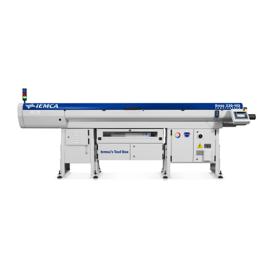
AUTOMATIC BAR FEEDER
EN
MANUAL FOR USE AND MAINTENANCE
KEYBOARD INSTRUCTION MANUAL
SPARE PARTS BOOK
SCHEMATICS
EC CONFORMITY DECLARATION FOR MACHINE
BOSS 332-545 E - 552 HD
BOSS 332r-545r E - 552r HD
MANUAL FOR USE AND MAINTENANCE
Rel. 2
Date
S/N
COMPILER:
ON APPROVAL:
ATTACHMENTS LIST
30/01/2010
Cod.
Bosi Andrea
Ghinassi Andrea
346005410
Advertisement
Table of Contents

Subscribe to Our Youtube Channel
Related Manuals for IEMCA BOSS 332


Summary of Contents for IEMCA BOSS 332
- Page 1 ATTACHMENTS LIST MANUAL FOR USE AND MAINTENANCE KEYBOARD INSTRUCTION MANUAL SPARE PARTS BOOK SCHEMATICS EC CONFORMITY DECLARATION FOR MACHINE BOSS 332-545 E - 552 HD BOSS 332r-545r E - 552r HD MANUAL FOR USE AND MAINTENANCE Rel. 2 Date 30/01/2010 Cod.
- Page 3 Tel. 0546/698000 - Fax. 0546/46338 - 0546/46224 TLX 550879 TYPE OF DOCUMENT: MANUAL FOR USE AND MAINTENANCE PRODUCT: AUTOMATIC BAR FEEDER MODEL: BOSS 332-545 E - 552 HD BOSS 332r-545r E - 552r HD IEMCA S.p.A. Via Granarolo, 167 Tel. 0546/698000 - Fax. 0546/46224 TLX 550879...
- Page 5 Should the bar feeder be used together with machine tools that do not have the CE marking, Iemca reminds to their clients that they should assess if the device is in compliance with Directive 2009/104/EC and subsequent amendments even after installing the bar feeder.
- Page 7 (2006/42/ EC Regulation, Enclosure II, Part A) Mr. TOMASO TAROZZI, acting as MANAGING DIRECTOR CEO and delegated by the company I G M I S.p.A. DIVISIONE IEMCA with legal office and establishment in Via Granarolo, 167 – 48018 FAENZA (RA) as manufacturer, DECLARES...
- Page 9 GENERAL INFORMATION BOSS 332/545/552 HD TECHNICAL INFORMATION BOSS 332/545/552 HD SAFETY PROCEDURES - GENERAL INFORMATION BOSS 332/545/552 HD HANDLING AND INSTALLATION BOSS 332/545/552 HD ADJUSTMENTS AND SETTING-UP BOSS 332/545/552 HD USE AND OPERATION BOSS 332/545/552 HD BAR FEEDER MAINTENANCE BOSS 332/545/552 HD...
-
Page 11: Table Of Contents
1 - GENERAL INFORMATION BOSS 332/545/552 HD INDEX WARRANTY CONDITIONS..................2 PURPOSE OF THE MANUAL..................3 MANUFACTURER AND BAR FEEDER IDENTIFICATION..........4 ASSISTANCE REQUEST ....................4 ATTACHMENT LIST ....................4 1 - Pag. 1 / 5... -
Page 12: Warranty Conditions
The warranty shall begin from the date on the “Installation Certificate” duly filled in and signed. The document must be sent by mail to: TECHNICAL SERVICE DEPARTMENT IEMCA division of IGMI spa 48018 Faenza (Ra) ITALY - Via Granarolo, 167 1 - Pag. 2 / 5... -
Page 13: Purpose Of The Manual
INFORMATION: The data included in this publication are only given as an example. IEMCA may apply changes to the model described in this publication at any time for any technical or business reason. Contact IEMCA service department for further information. -
Page 14: Manufacturer And Bar Feeder Identification
1 - GENERAL INFORMATION BOSS 332/545/552 HD MANUFACTURER AND BAR FEEDER IDENTIFICATION A Manufacturer identification. B EC mark of conformity. C Year of manufacture. D Bar feeder model. E Serial number. G Mains frequency. H Power consumption. M Supply voltage. - Page 15 1 - GENERAL INFORMATION BOSS 332/545/552 HD 1 - Pag. 5 / 5...
- Page 16 2 - TECHNICAL INFORMATION BOSS 332/545/552 HD INDEX BAR FEEDER GENERAL DESCRIPTION...............2 OPERATING CYCLE ....................4 SAFETY DEVICES .....................7 SAFETY PLATES - LOCATION AND DESCRIPTION ............9 VERSION DESCRIPTION ..................10 TECHNICAL DATA ....................11 2.6.1 Noise levels ......................25 ACCESSORIES - FOREWORD...................26 2.7.1 Bush holder device - Description ................26 2.7.2...
-
Page 17: Bar Feeder General Description
BOSS 552r HD (reversed version, magazine length: 32, 37, 44) Unless otherwise stated, the texts, tables and illustrations contained in this manual refer to the standard version (BOSS 332, BOSS 545 and BOSS 552 HD) with the lathe on the operator's right. - Page 18 2 - TECHNICAL INFORMATION BOSS 332/545/552 HD • MAIN PARTS A MAGAZINE; it stores the bars. B BAR SELECTION DEVICE; it enables the first bar to be lowered into the guide channels and holds the remaining bars in the magazine.
-
Page 19: Operating Cycle
2 - TECHNICAL INFORMATION BOSS 332/545/552 HD OPERATING CYCLE In the automatic operation mode, bar feeder movements are controlled in the sequence described below. The bar pusher "A" feeds bar "B" in the lathe, by following lathe pulses, until bar end. - Page 20 2 - TECHNICAL INFORMATION BOSS 332/545/552 HD Clamps "D" close again to check remnant "C" removal. If the remnant is still inserted in the bar pusher collet, the bar feeder stops; otherwise, it continues its cycle. Upper guide channels "H" open together with bar pusher "A";...
- Page 21 2 - TECHNICAL INFORMATION BOSS 332/545/552 HD When the first feeding carriage "M" completes its stroke, the required space has been created for bar pusher insertion. The first feeding carriage performs the return stroke. Upper guide channels "H" are closed; bar pusher "A"...
-
Page 22: Safety Devices
2 - TECHNICAL INFORMATION BOSS 332/545/552 HD SAFETY DEVICES A EMERGENCY BUTTON; when pressed, all bar feeder and lathe functions are stopped in an emergency condition. B EMERGENCY BUTTON; when pressed, all bar feeder and lathe functions are stopped in an emergency condition. - Page 23 2 - TECHNICAL INFORMATION BOSS 332/545/552 HD D FIXED GUARD: it is made of transparent material to allow visual inspection of the bar magazine area. E FIXED GUARD: it prevents accidental access to the bar selection area. F FIXED GUARD: it prevents unintentional access to the drive area.
-
Page 24: Safety Plates - Location And Description
2 - TECHNICAL INFORMATION BOSS 332/545/552 HD SAFETY PLATES - LOCATION AND DESCRIPTION A Crushing danger of the upper limbs. B Pay attention to the moving parts. C Prohibition of removing the safety enclosures. D Wear safety gloves and shoes. -
Page 25: Version Description
2 - TECHNICAL INFORMATION BOSS 332/545/552 HD VERSION DESCRIPTION Maximum bar length Minimum Minimum Maximum length Model Version length (CSS) length (CSM) mm (ft) mm (ft) mm (ft) 2080 (6,8) BOSS 332 3200 (10,5) 1000 BOSS 545 3740 (12,2) BOSS 552HD... -
Page 26: Technical Data
(*) Without axial displacement device, the minimum value can be decreased to 850 mm. Overall dimensions Model Version A (mm) B (mm) C (mm) 2603 3802 1220 BOSS 332 – BOSS 332r 4342 1760 BOSS 545 - BOSS 545r BOSS 552 - BOSS 552r 5002 2420 6382 1979 1520... - Page 27 2 - TECHNICAL INFORMATION BOSS 332/545/552 HD General technical data BOSS 332 BOSS 545/552-HD Max 545 45 mm Ø Min 4 mm Ø Max 32 mm Ø Min 5 mm (1” ¾) Round bar size (5/32") (1" 1/4) (3/16") Max 552 52 mm (2”)(***)
- Page 28 2 - TECHNICAL INFORMATION BOSS 332/545/552 HD BOSS 332 BOSS 545/552-HD 230/400 Volt 230/400 Volt Power supply voltage Mains frequency 50/60 Hz 50/60 Hz 24 Volt D.C. 24 Volt D.C. Control voltage Installed power 2 kW 2 kW 57 l...
- Page 29 2 - TECHNICAL INFORMATION BOSS 332/545/552 HD Working axis height Upper screws X (mm) Y (mm) Model position Working axis height Max. loading height 865÷905 1055 900÷940 1090 935÷975 1125 970÷1010 1160 BOSS 332 1005÷1045 1195 BOSS 545 1040÷1080 1230 BOSS 552 - HD 1070÷1115...
- Page 30 2 - TECHNICAL INFORMATION BOSS 332/545/552 HD Working axis height with axial displacement Upper screws X (mm) Y (mm) Model position Working axis height Max. loading height 905÷950 1100 945÷995 1135 980÷1020 1160 1015÷1055 1205 BOSS 332 1050÷1090 1240 BOSS 545 1095÷1125...
- Page 31 2 - TECHNICAL INFORMATION BOSS 332/545/552 HD Working axis height with axial displacement Vers. 21. Screw position X (mm) – Loading Model (threaded holes on the Screws axis height base) 900 ÷ 920 1 - 3 921 ÷ 955 2 - 4 956 ÷...
- Page 32 2 - TECHNICAL INFORMATION BOSS 332/545/552 HD BOSS 332 guide channel, bar pusher, bar and pipe diameters. Guide Bar diameter (mm) Bar pusher Pipe channel Model diameter diameter diameter Minimum Maximum (mm) (mm) (*) (mm) BOSS 332 (*) Valid also for prepared bars or normal bars machined with front remnant ejection.
- Page 33 2 - TECHNICAL INFORMATION BOSS 332/545/552 HD WARNING – CAUTION: diameters for barstocks in any guide channel are only given as an indication. A diameter of a bar to be machined approximately 10 mm smaller than the guide channel diameter may cause vibration and failure to the bar feeder. Therefore, it may be necessary to slow down the bar rotation speed or to change the guide channel diameter in order to obtain the best performance.
- Page 34 2 - TECHNICAL INFORMATION BOSS 332/545/552 HD BOSS 545 guide channel, bar pusher, bar and pipe diameters. Guide Bar diameter (mm) Bar pusher Pipe channel Model diameter diameter diameter Minimum Maximum (mm) (mm) (*) (mm) BOSS 545 (*) Valid also for prepared bars or normal bars machined with front remnant ejection.
- Page 35 2 - TECHNICAL INFORMATION BOSS 332/545/552 HD WARNING – CAUTION: diameters for barstocks in any guide channel are only given as an indication. A diameter of a bar to be machined approximately 10 mm smaller than the guide channel diameter may cause vibration and failure to the bar feeder. Therefore, it may be necessary to slow down the bar rotation speed or to change the guide channel diameter in order to obtain the best performance.
- Page 36 2 - TECHNICAL INFORMATION BOSS 332/545/552 HD BOSS 552 HD guide channel, bar pusher, bar and pipe diameters. Guide Bar diameter (mm) Bar pusher Pipe channel Model diameter diameter diameter Minimum Maximum (mm) (mm) (*) (mm) BOSS 552-HD (*) Valid also for prepared bars or normal bars machined with front remnant ejection.
- Page 37 2 - TECHNICAL INFORMATION BOSS 332/545/552 HD WARNING – CAUTION: diameters for barstocks in any guide channel are only given as an indication. A diameter of a bar to be machined approximately 10 mm smaller than the guide channel diameter may cause vibration and failure to the bar feeder. Therefore, it may be necessary to slow down the bar rotation speed or to change the guide channel diameter in order to obtain the best performance.
- Page 38 2 - TECHNICAL INFORMATION BOSS 332/545/552 HD BOSS 332 guide channel lubricating oils BOSS 545/552HD guide channel lubricating oils ISO/UNI Brand Name ISO/UNI Brand Name rating rating Agip Acer 100 Agip Acer 150 Api Cis 100 Api Cis 150 Aral Degol TU...
- Page 39 2 - TECHNICAL INFORMATION BOSS 332/545/552 HD Air lubricator oils ISO/UNI rating Brand Name Energal HLP32 CASTROL Hyspin AWS32 CENTURY PWLA Elfoina 32 ESSO Nuto H32 ISO 3448 GULF Harmony 32 MOBIL SHC 524 MOBIL DTE 24 MOBIL DTE Oil Light...
-
Page 40: Noise Levels
2 - TECHNICAL INFORMATION BOSS 332/545/552 HD 2.6.1 Noise levels The bar feeder does not cause acoustic noise. The noise occurs when the lathe, to which the bar feeder is connected, is working and the bar is rotating into the bar feeder guide channels. -
Page 41: Accessories - Foreword
2 - TECHNICAL INFORMATION BOSS 332/545/552 HD ACCESSORIES - FOREWORD To improve the bar feeder performance and increase its versatility, the following optional devices are available: 2.7.1 Bush holder device - Description It is attached to the front part of the bar feeder. -
Page 42: Axial Displacement Device - Description
Overall dimensions Model Version A (mm) B (mm) 1880 BOSS 332 – BOSS 332r 3170 BOSS 545 - BOSS 545r 3770 BOSS 552 HD- BOSS 552r-HD 4370 2 - Pag. 27 / 32... -
Page 43: Device For Sliding Headstock Lathes - Foreword
2 - TECHNICAL INFORMATION BOSS 332/545/552 HD DEVICE FOR SLIDING HEADSTOCK LATHES - FOREWORD This bar feeder has been designed and manufactured to be coupled to sliding headstock lathes too. To do this, special devices are available which are listed and then described below. -
Page 44: Telescopic Front Nose - Description
2 - TECHNICAL INFORMATION BOSS 332/545/552 HD 2.8.2 Telescopic front nose - Description It is used to optimize bar guiding between the bush holder device and the lathe spindle. Maximum stroke and overall dimension Maximum stroke Overall dimensions Model A (mm) -
Page 45: Devices For Cam Lathes - Foreword
2 - TECHNICAL INFORMATION BOSS 332/545/552 HD DEVICES FOR CAM LATHES - FOREWORD This bar feeder has been designed and manufactured to be coupled to cam lathes too. To do this, special devices are available which are listed and then described below. -
Page 46: Camshaft Release Device - Description
2 - TECHNICAL INFORMATION BOSS 332/545/552 HD 2.9.3 Camshaft release device - Description Releases and engages the camshaft during the bar change phase. A radial version and an axial version of this device are available. Radial version Axial version 2 - Pag. 31 / 32... - Page 47 2 - TECHNICAL INFORMATION BOSS 332/545/552 HD 2 - Pag. 32 / 32...
- Page 48 3 - SAFETY PROCEDURES - GENERAL INFORMATION BOSS 332/545/552 HD INDEX GENERAL SAFETY REGULATIONS................2 HANDLING AND INSTALLATION - Safety ..............3 ADJUSTMENTS AND SETUP - Safety................3 USE AND OPERATION - Safety..................4 BAR FEEDER MAINTENANCE - Safety ................5 3 - Pag. 1 / 6...
- Page 49 Strictly comply with the health and safety regulations at work issued by the relevant authorities in each country. • IEMCA declines any liability for injury to persons or damage to property if the relevant safety regulations are disregarded. 3 - Pag. 2 / 6...
- Page 50 3 - SAFETY PROCEDURES - GENERAL INFORMATION BOSS 332/545/552 HD HANDLING AND INSTALLATION - Safety • The bar feeder must be handled using suitable means and methods only. • Do not stand or transit underneath a suspended load, or within the range of action of the crane, elevator carriage or other suitable lifting and transport means.
- Page 51 3 - SAFETY PROCEDURES - GENERAL INFORMATION BOSS 332/545/552 HD USE AND OPERATION - Safety • The work area around the bar feeder must always be kept clean and free of clutter and its surface must be slip resistant in order to allow immediate access to emergency devices and bar loading to be performed without creating obstructions or danger.
- Page 52 • Keep drain oil in suitable containers and deliver it to companies specialized in the storage and disposal of polluting waste products. • Avoid environmental pollution. • Use original IEMCA spare parts only. 3 - Pag. 5 / 6...
- Page 53 3 - SAFETY PROCEDURES - GENERAL INFORMATION BOSS 332/545/552 HD 3 - Pag. 6 / 6...
- Page 54 4 - HANDLING AND INSTALLATION BOSS 332/545/552 HD INDEX PACKAGING ......................3 LIFTING ......................3 INSTALLATION AREA - FEATURES ..............6 BAR FEEDER WITHOUT AXIAL DISPLACEMENT DEVICE - INSTALLATION .....7 4.4.1 Backing plates and support feet - Installation.............7 4.4.2 Height - Adjustment ....................7 4.4.3...
- Page 55 4 - HANDLING AND INSTALLATION BOSS 332/545/552 HD 4.7.1 Headstock return device ..................24 4.7.2 Cam box ........................25 4.7.3 Camshaft release device ..................26 LUBRICATION OIL - FILLING ................28 ELECTRICAL CONNECTION ................29 4.9.1 THREE-PHASE POWER SUPPLY ................29 4.9.2 SAFETY SIGNALS ....................29 4.9.2.1 EMERGENCY STOP ....................30...
- Page 56 4 - HANDLING AND INSTALLATION BOSS 332/545/552 HD PACKAGING There are three possible bar feeder packaging: A WITHOUT PACKAGING. B WITH PALLET: the bar feeder is placed on a pallet and wrapped with protective film. C WITH CRATE: the bar feeder is contained in a crate and wrapped with protective film.
- Page 57 4 - HANDLING AND INSTALLATION BOSS 332/545/552 HD LIFTING WITH NO PACKAGING • Install two round-eye eyebolts "A" with threaded stem (1 UNI - ISO3266 M20). • Use a hook type lifting device of suitable capacity. DANGER - WARNING: During...
- Page 58 4 - HANDLING AND INSTALLATION BOSS 332/545/552 HD LIFTING WITH CRATE • Use a hook (or fork) type lifting device of suitable capacity (see information on packaging). DANGER - WARNING: never lifting systems devices different from the ones above. 4 - Pag. 5 / 32...
- Page 59 Without axial displacement With axial displacement Overall dimensions Model Version A (mm) B (mm) C (mm) 2603 3802 BOSS 332 - BOSS 332r 4342 BOSS 545 - BOSS 545r BOSS552 HD-BOSS552r HD 5002 6382 4 - Pag. 6 / 32...
- Page 60 4 - HANDLING AND INSTALLATION BOSS 332/545/552 HD BAR FEEDER WITHOUT AXIAL DISPLACEMENT DEVICE - INSTALLATION Before carrying out the bar feeder installation, check the lathe stability; make sure that it is firmly fixed to the ground and that the spindle axis is perfectly in horizontal position.
- Page 61 100 mm to allow the bar feeder to be brought as close as possible to the lathe; contact IEMCA After-sales Service for more information. DANGER - WARNING: Perform bar pusher extension manually. Please,...
- Page 62 4 - HANDLING AND INSTALLATION BOSS 332/545/552 HD • Roughly adjust the height of the working axis and the alignment with the lathe by turning the screws of the support feed. 4.4.4 Sleeve - Installation BOSS 332 • Install the sleeve "A" in the bush holder device.
- Page 63 4 - HANDLING AND INSTALLATION BOSS 332/545/552 HD BOSS 545 - BOSS 552 - HD • Install the sleeve "A" in the bush holder device. • Install the oil recovery tank "B". • Connect the drain pipe to the tank...
- Page 64 4 - HANDLING AND INSTALLATION BOSS 332/545/552 HD 4.4.5 Levelling and alignment FOREWORD Alignment between the bar feeder and lathe is the most critical installation phase; therefore, this operation should be carried out by experienced personnel with the greatest accuracy.
- Page 65 4 - HANDLING AND INSTALLATION BOSS 332/545/552 HD LEVELLING • Insert the templates in the specially provided holes in the beam. • Check the levelling by positioning the level crosswise and lengthwise. • Carry out the required corrections by turning the support feet screws.
- Page 66 4 - HANDLING AND INSTALLATION BOSS 332/545/552 HD ALIGNMENT • Insert the (supplied) crank in the intermediate drive shaft and move the bar pusher to its backwards limit stop. • Move the crank to the guide channel opening screw shaft and open the upper guides.
- Page 67 4 - HANDLING AND INSTALLATION BOSS 332/545/552 HD • use a sliding caliper to check alignment near the sleeve "C" and the spindle "D"; adopt a tolerance of 0.15 mm in all four directions. • prepare a perfectly straight ground bar, with...
- Page 68 Wherever possible, the bar feeder should be fixed to the lathe with a suitable coupling unit according to lathe brand and type. The figure shows a general example of fixing; contact IEMCA service department for more information. 4 - Pag. 15 / 32...
- Page 69 4 - HANDLING AND INSTALLATION BOSS 332/545/552 HD 4.4.7 Telescopic front nose - Installation If the bar feeder is equipped with a telescopic front nose, proceed as described below. • Remove the fixed sleeve that had been installed to obtain alignment between the bar feeder and the lathe.
- Page 70 4 - HANDLING AND INSTALLATION BOSS 332/545/552 HD BAR FEEDER WITH AXIAL DISPLACEMENT DEVICE - INSTALLATION Before carrying out the installation of the bar feeder, check lathe stability; make sure that it is firmly fixed to the ground and with a perfectly horizontal spindle axis.
- Page 71 4 - HANDLING AND INSTALLATION BOSS 332/545/552 HD 4.5.3 Preliminary positioning • Position the bar feeder behind the lathe, by taking into account the fixed dimensions and side plays of both machines and the coupling distance (see "B" in the "PRELIMINARY POSITIONING"...
- Page 72 4 - HANDLING AND INSTALLATION BOSS 332/545/552 HD 4.5.5 Levelling and alignment FOREWORD The alignment between the bar feeder and lathe is the most critical phase; therefore, this operation should be carried out with the greatest accuracy by experienced personnel.
- Page 73 4 - HANDLING AND INSTALLATION BOSS 332/545/552 HD • Position the remaining eight plates under the axial displacement sliding frame in the positions indicated in the figure, then tighten the cone end grub screws "B". 4 - Pag. 20 / 32...
- Page 74 4 - HANDLING AND INSTALLATION BOSS 332/545/552 HD 4.5.6 Bar feeder fastening Ground fastening • Drill the floor and fix the (axial displacement) frame with expansion plugs. • Check the levelling and alignment. • Tighten nuts "A" and screws "B".
- Page 75 4 - HANDLING AND INSTALLATION BOSS 332/545/552 HD DEVICE FOR SLIDING HEADSTOCK LATHES - INSTALLATION 4.6.1 Bar-headstock synchronization device • Open the upper guard. INFORMATION: the figure shows a general example of installation; contact IEMCA service department for more information.
- Page 76 4 - HANDLING AND INSTALLATION BOSS 332/545/552 HD 4.6.2 Air adjusting unit FILTER A • Make sure that cup "B" is not full of condensation. If needed, drain the condensate by acting on valve "C". • Check pressure switch adjustment, see section 5.2.3...
- Page 77 4 - HANDLING AND INSTALLATION BOSS 332/545/552 HD DEVICES FOR CAM LATHES - INSTALLATION 4.7.1 Headstock return device • Open the upper guard. INFORMATION: the figure shows a general example of installation; contact IEMCA service department for more information. •...
- Page 78 4 - HANDLING AND INSTALLATION BOSS 332/545/552 HD • Install the (original lathe) spring "G" and adjust its tension by acting on the ring nut "H". WARNING: A double cylinder piston is fitted on lathes with very fast headstock stroke acceleration.
- Page 79 4 - HANDLING AND INSTALLATION BOSS 332/545/552 HD 4.7.3 Camshaft release device INFORMATION: the figures show a general example of installation; contact IEMCA service department for more information. Radial version • Assemble the articulation "A" in the flange "B". •...
- Page 80 4 - HANDLING AND INSTALLATION BOSS 332/545/552 HD Axial version • Drill and thread the lathe housing to fix the transmission unit "F" and assemble the disk "G" in the control "H". • Insert the shaft "L" in the joint "M" and lock it with a pin;...
- Page 81 4 - HANDLING AND INSTALLATION BOSS 332/545/552 HD After completing the above-described operations, the actuator rotation stroke should be adjusted (this operation is necessary for both the radial version and the axial version). • Loosen the screws, move slides "Q" and tighten screws "P".
- Page 82 4 - HANDLING AND INSTALLATION BOSS 332/545/552 HD ELECTRICAL CONNECTION DANGER - WARNING: this type of operation should only be entrusted to skilled personnel with precise technical competence and specific abilities to comply with the applicable standards and regulations in force.
- Page 83 Therefore, they should be removed in order to restore the safeties. DANGER-WARNING !!! The bar feeder safety depends on these connections, therefore IEMCA is not responsible for any possible damage to persons or things, caused by improper use of the above mentioned signals.
- Page 84 4 - HANDLING AND INSTALLATION BOSS 332/545/552 HD 4.9.3 FUNCTION SIGNALS The bar feeder can send and receive all the signals which are necessary to its correct operation. These signals are driven by a PLC, and can be grouped into: inputs (signals from lathe to bar feeder) and outputs (signals from bar feeder to lathe).
- Page 85 4 - HANDLING AND INSTALLATION BOSS 332/545/552 HD 4.10 PNEUMATIC CONNECTION • Fill the tank of lubricator "A" removing plug "B" or cup "C"; the oil level must reach the MAX. reference. See the "Technical Data" section, Ch. 6, for the oil comparative table.
- Page 86 5 - ADJUSTMENTS AND SETTING-UP BOSS 332/545/552 HD INDEX ADJUSTMENT AND SETUP - FOREWORD ............2 GENERAL ADJUSTMENTS - FOREWORD ..............3 5.2.1 Feeding chain - Adjustment ..................3 5.2.2 Air adjusting unit - Adjustment .................3 SETUP ACCORDING TO THE BAR TO BE MACHINED ..........4 5.3.1...
- Page 87 5 - ADJUSTMENTS AND SETTING-UP BOSS 332/545/552 HD ADJUSTMENT AND SETUP - FOREWORD DANGER - WARNING: do not perform any adjustment when the bar feeder is running unless expressly requested in the manual. In addition to normal adjustments throughout its service life, this bar feeder also needs set-up according to the type of operation.
- Page 88 5 - ADJUSTMENTS AND SETTING-UP BOSS 332/545/552 HD GENERAL ADJUSTMENTS - FOREWORD All the necessary adjustments for correct bar feeder operation are included. They may become necessary for maintenance, troubleshooting or component replacement. 5.2.1 Feeding chain - Adjustment For the movement chain of the bar pusher, tension screws A on the rear plate of bar feeder is provided.
- Page 89 The table reports the diameters of available guide channels as well as the range of the bar pushers that can be assembled, and the diameters of the bar to be machined. BOSS 332 guide channel, bar pusher, bar and pipe diameters. Guide...
- Page 90 5 - ADJUSTMENTS AND SETTING-UP BOSS 332/545/552 HD WARNING – CAUTION: diameters for barstocks in any guide channel are only given as an indication. A diameter of a bar to be machined approximately 10 mm smaller than the guide channel diameter may cause vibration and failure to the bar feeder. Therefore, it may be necessary to slow down the bar rotation speed or to change the guide channel diameter in order to obtain the best performance.
- Page 91 5 - ADJUSTMENTS AND SETTING-UP BOSS 332/545/552 HD BOSS 545 guide channel, bar pusher, bar and pipe diameters. Guide Bar diameter (mm) Bar pusher Pipe channel Model diameter diameter diameter Minimum Maximum (mm) (mm) (*) (mm) BOSS 545 (*) Valid also for prepared bars or normal bars machined with front remnant ejection.
- Page 92 5 - ADJUSTMENTS AND SETTING-UP BOSS 332/545/552 HD WARNING – CAUTION: diameters for barstocks in any guide channel are only given as an indication. A diameter of a bar to be machined approximately 10 mm smaller than the guide channel diameter may cause vibration and failure to the bar feeder. Therefore, it may be necessary to slow down the bar rotation speed or to change the guide channel diameter in order to obtain the best performance.
- Page 93 5 - ADJUSTMENTS AND SETTING-UP BOSS 332/545/552 HD BOSS 552 - HD guide channel, bar pusher, bar and pipe diameters. Guide Bar diameter (mm) Bar pusher Pipe channel Model diameter diameter diameter Minimum Maximum (mm) (mm) (*) (mm) BOSS 552 - HD (*) Valid also for prepared bars or normal bars machined with front remnant ejection.
- Page 94 5 - ADJUSTMENTS AND SETTING-UP BOSS 332/545/552 HD WARNING – CAUTION: diameters for barstocks in any guide channel are only given as an indication. A diameter of a bar to be machined approximately 10 mm smaller than the guide channel diameter may cause vibration and failure to the bar feeder. Therefore, it may be necessary to slow down the bar rotation speed or to change the guide channel diameter in order to obtain the best performance.
- Page 95 5 - ADJUSTMENTS AND SETTING-UP BOSS 332/545/552 HD Example 1 The previous machining cycle had been carried out under these conditions: Guide channel Bar pusher diameter Bar diameter (mm) diameter (mm) (mm) The new machining cycle requires feeding of 10 mm bars.
- Page 96 5 - ADJUSTMENTS AND SETTING-UP BOSS 332/545/552 HD 5.3.1 Guide channels, half bushes, bar pusher and collet - Replacement • When the magazine is empty (no bars), set the bar feeder to manual mode. • Open the upper guard. •...
- Page 97 5 - ADJUSTMENTS AND SETTING-UP BOSS 332/545/552 HD • Move the first feeding carriage forwards until the flag reaches the opening, then remove it from its seat. • Disassemble the lower guide channels. • Disassemble the upper guide channels. 5 - Pag. 12 / 34...
- Page 98 5 - ADJUSTMENTS AND SETTING-UP BOSS 332/545/552 HD • Remove the bar pusher support. A Guide channels Ø=13÷46 B Guide channels Ø=52 1 Support 2 Spacer Remove the sleeve in the following way: Fixed sleeve • Remove the oil recovery device "A" and sleeve "B".
- Page 99 "A" and extract the lower bush • Close the remaining half bush by acting on the shaft "A", and extract it. Only for BOSS 332 • Remove the internal sleeve. 5 - Pag. 14 / 34...
- Page 100 5 - ADJUSTMENTS AND SETTING-UP BOSS 332/545/552 HD • If necessary, remove the lathe spindle liner and install another one suitable for the diameter of the guide channels. Install front half bushes suitable for the bar in the following way: BOSS 332 •...
- Page 101 5 - ADJUSTMENTS AND SETTING-UP BOSS 332/545/552 HD Only for BOSS 332 • Install an internal sleeve suitable for the guide channel. Reassemble the sleeve as follows: Fixed sleeve • Install the sleeve "B" suitable for diameter of the guide channels and the oil recovery device "A".
- Page 102 5 - ADJUSTMENTS AND SETTING-UP BOSS 332/545/552 HD Telescopic front nose When replacing the telescopic front nose, it is not necessary to change completely the unit, but only some parts supplied with the spare parts kit. • Press the intermediate stage to the end of its stroke and remove the ring "C".
- Page 103 5 - ADJUSTMENTS AND SETTING-UP BOSS 332/545/552 HD • Place the sleeve back into its seat. Only for BOSS 332 If the "new" guide channel diameter is 13 mm, the intermediate flag should be replaced as follows. • Remove the two rings "A", the spring "B" and the gate •...
- Page 104 IEMCA service department for further information. Legend: 1 "IEMCA" pipe collet 2 "IEMCA" bar collet 3 "IEMCA" collet for bars machined with front remnant ejection 4 Quick coupling collet for bars 5 Ring 6 Collet connection 5 - Pag. 19 / 34...
- Page 105 5 - ADJUSTMENTS AND SETTING-UP BOSS 332/545/552 HD WARNING – CAUTION: At every collet change (model 381p, 381p..011, 381p..021 e 386p) it is necessary to install the grub screw H and the counter screw L. WARNING – CAUTION: the collet external diameter should be at least 0.5 mm smaller than the bar pusher...
- Page 106 5 - ADJUSTMENTS AND SETTING-UP BOSS 332/545/552 HD • Install the first feeding carriage into its seat. • Bring the first feeding carriage to its backward stroke limit and insert the bar pusher. • Move the bar pusher forwards past the clamps area.
- Page 107 5 - ADJUSTMENTS AND SETTING-UP BOSS 332/545/552 HD • Close the guard. • On the keyboard, press the two blue buttons and the guide channel closing button simultaneously to close the guide channels. • Bring the bar pusher to its backward limit stop by means of the keyboard.
- Page 108 5 - ADJUSTMENTS AND SETTING-UP BOSS 332/545/552 HD Open the guard and proceed as follows: • Loose the screw, adjust the flag position and tighten the screw. • Close the upper guide channels. • Move the bar pusher forwards and backwards in the flag area to make sure that its stroke is not hindered.
- Page 109 5 - ADJUSTMENTS AND SETTING-UP BOSS 332/545/552 HD 5.3.2 BAR PUSHER REPLACEMENT PROCEDURE WARNING - CAUTION Never perform the following procedure when a bar is detected in the bar pusher collet! The replacement of the bar pusher, for a working cycle change or maintenance, may be...
- Page 110 5 - ADJUSTMENTS AND SETTING-UP BOSS 332/545/552 HD Close the guide channels Restore the machining cycle of the bar feeder. 5 - Pag. 25 / 34...
- Page 111 (e.g. when changing over from round bars to square or hexagonal bars). Contact IEMCA after-sales service for more information. Proceed as follows to replace the clamps: •...
- Page 112 5 - ADJUSTMENTS AND SETTING-UP BOSS 332/545/552 HD • Loosen screws "A" and replace the clamp. • Restore the bar feeder initial operating conditions. 5 - Pag. 27 / 34...
- Page 113 5 - ADJUSTMENTS AND SETTING-UP BOSS 332/545/552 HD 5.3.4 Bar guide plates and bar selectors - Adjustment Preliminary procedure • Open the upper guard. • Close the upper guide channels (sensor "A" must be energized). • Make sure that the bar selectors are lower than the magazine rack.
- Page 114 5 - ADJUSTMENTS AND SETTING-UP BOSS 332/545/552 HD Bar guide plate adjustment • Loosen the handle "A", lift the plate and tighten the handle "A"; repeat this operation on all the plates. • Load the two bars into the magazine, loosen the handle "A"...
- Page 115 5 - ADJUSTMENTS AND SETTING-UP BOSS 332/545/552 HD Bar selector adjustment Make the adjustment as follows. • Use screw "B" to adjust the transverse position of bar stop "A" so that selectors "C" lift just one bar. • Open the upper guide channels; the first bar...
- Page 116 5 - ADJUSTMENTS AND SETTING-UP BOSS 332/545/552 HD CAM BOX - TIMING If the bar feeder is equipped with a cam box, each cam should be timed to its own microswitch. The timing procedure is as follows. MICROSWITCH FUNCTION S90 - Bar feeding enabling signal It controls the bar feeding motor start/stop.
- Page 117 5 - ADJUSTMENTS AND SETTING-UP BOSS 332/545/552 HD CAM TIMING LATHE CAM COMPLETE CYCLE PHASE HEADSTOCK PHASE COLLET LATHE BAR FEEDER CAM COMPLETE CYCLE PHASE MICROSWITCH PHASE MICROSWITCH PHASE MICROSWITCH A STROKE CLOSED B FEEDING OPEN C FORWARD STOP CLOSED...
- Page 118 5 - ADJUSTMENTS AND SETTING-UP BOSS 332/545/552 HD Microswitches S90 and S91 • Manually rotate shaft "A" up to a distance of 10° approx. from the collet opening, then rotate the cam of "S90" microswitch until wheel "B" is released.
- Page 119 5 - ADJUSTMENTS AND SETTING-UP BOSS 332/545/552 HD Microswitch S92 • Manually rotate shaft "A" until the headstock starts its return stroke with closed collet. • Release the "S92" microswitch wheel. • Continue rotation until the headstock has completed its return stroke.
- Page 120 6 - USE AND OPERATION BOSS 332/545/552 HD INDEX CONTROL DESCRIPTION ..................2 KEYBOARD CONTROL DESCRIPTION.................4 LIGHT INDICATOR - SIGNAL DESCRIPTION ..............8 BARS TO BE MACHINED - FEATURES AND PREPARATION ..........9 6.4.1 BAR STRAIGHTNESS - Measurement ...............11 BAR FEEDER SET-UP AND AUTOMATIC CYCLE START..........13 6.5.1...
- Page 121 6 - USE AND OPERATION BOSS 332/545/552 HD CONTROL DESCRIPTION INFORMATION: It is possible to start the bar feeder in automatic mode from the handheld keyboard, even when lathe 'MAN/AUT' signal is in Manual mode. INFORMATION: When the bar feeder is in Automatic mode, bar feeding is possible only when the Lathe 'MAN/AUT' signal is in Automatic mode.
- Page 122 6 - USE AND OPERATION BOSS 332/545/552 HD The figure indicates the positions of both the electrical and handheld keyboard "1" controls. 2 MAIN SWITCH: turns the power supply on and off. Position 0 (OFF) the machine is not powered.
- Page 123 6 - USE AND OPERATION BOSS 332/545/552 HD KEYBOARD CONTROL DESCRIPTION 1 Start buttons: opposite buttons enabling the keys for some functions. Press both buttons and simultaneously the button corresponding to the desired function. 2 Selects the automatic function. It stops the bar feeder: for restart, manually release the push-button.
- Page 124 6 - USE AND OPERATION BOSS 332/545/552 HD 15 Lifts and lowers the bar selectors (LED on when selector switches are at their "down" position). 6 - Pag. 5 / 24...
- Page 125 6 - USE AND OPERATION BOSS 332/545/552 HD 16 Multifunction Sets the numerical value. Opens the guide channels. Push both start buttons and then the key; release both buttons and the key only when the movement is finished. 17 Moves the bar pusher at high speed.
- Page 126 6 - USE AND OPERATION BOSS 332/545/552 HD In "Automatic" mode, if pressed, the half-bushes will open and close, according to the selected sequence. If pressed again, the half-bushes will remain open during the entire operating cycle. 6 - Pag. 7 / 24...
- Page 127 6 - USE AND OPERATION BOSS 332/545/552 HD LIGHT INDICATOR - SIGNAL DESCRIPTION BLINKING GREEN LIGHT; it indicates that the bar feeder is in the automatic mode. BLINKING RED LIGHT; it indicates that the bar feeder is not operating, or that it is in the manual mode.
- Page 128 6 - USE AND OPERATION BOSS 332/545/552 HD BARS TO BE MACHINED - FEATURES AND PREPARATION WARNING – CAUTION: do not insert bars having different sizes than the ones set by the manufacturer. clean the bar surface before loading bars.
- Page 129 6 - USE AND OPERATION BOSS 332/545/552 HD Please find hereafter some advices to optimise the bar feeder performances. Usually it is not necessary to perform preliminary operations on the bar ends, but to obtain optimum results during loading, it is advisable to chamfer them.
- Page 130 6 - USE AND OPERATION BOSS 332/545/552 HD 6.4.1 BAR STRAIGHTNESS - Measurement The bar vibrations are partially due to the state of the bar itself: if the bar is not perfectly straight, it can cause vibrations. Round bars As stated also in the UNI-10233/2 regulation, the...
- Page 131 6 - USE AND OPERATION BOSS 332/545/552 HD Hexagonal, square and section bars With shaped bars, insert some bushes on the bar to be controlled. Position 2 bushes on both V-supports. In that case, the measurement can be carried out as shown in the figure.
- Page 132 6 - USE AND OPERATION BOSS 332/545/552 HD BAR FEEDER SET-UP AND AUTOMATIC CYCLE START The following list is a sequence of bar feeder setup and automatic cycle feeding operations required if the bar feeder has to be started for the first time.
- Page 133 6 - USE AND OPERATION BOSS 332/545/552 HD 6.5.1 Bar magazine - Filling WARNING – CAUTION: do not manually lift loads with weights exceeding those foreseen applicable regulations force; necessary use a suitable lifting device. WARNING – CAUTION: wear personal protections according to the regulations in force.
- Page 134 6 - USE AND OPERATION BOSS 332/545/552 HD 6.5.2 Lubrication oil - Flow adjustment The oil flow in the guide channels and bush holder device is automatically controlled during the bar feeder automatic cycle. The pump is started when the bar feeder has completed the bar change and stops when the bar pusher approaches the bush holder device.
- Page 135 6 - USE AND OPERATION BOSS 332/545/552 HD 6.5.3 Automatic cycle start • Power the lathe on. • Turn the main switch to position I (ON). • Press [pupa_boss_barra] to start the bar feeder. • Press to select the manual mode.
- Page 136 6 - USE AND OPERATION BOSS 332/545/552 HD 6.5.4 Guide channel opening/closing procedure The following instructions concern guide channel opening and closing in the manual function. OPENING PROCEDURE Open the guide channels by pressing the start buttons and ; if the carriage "A"...
- Page 137 6 - USE AND OPERATION BOSS 332/545/552 HD 6.5.5 Mode of performing a cycle in the STEP BY STEP function Foreword This mode may be used for many reasons, as for instance: • to check a complete bar change cycle;...
- Page 138 6 - USE AND OPERATION BOSS 332/545/552 HD • Stop the bar feeder by pressing • Stop the lathe. • Turn the main power switch to O (OFF). 6 - Pag. 19 / 24...
- Page 139 6 - USE AND OPERATION BOSS 332/545/552 HD AUTOMATIC CYCLE START AFTER MANUAL CYCLE OPERATIONS • If the bar pusher has been moved while power supply was disconnected, the "BAR FEEDER ZERO SETTING" should be performed as follows: press the start buttons and if the upper guide channels are not closed, the bar feeder will not perform the "BAR FEEDER ZERO SETTING";...
- Page 140 6 - USE AND OPERATION BOSS 332/545/552 HD • Press 6 - Pag. 21 / 24...
- Page 141 6 - USE AND OPERATION BOSS 332/545/552 HD MACHINING CHANGE - QUICK GUIDE The purpose of this section is to provide the operator with a quick guide to the operations required for machining type change (either with or without guide channel change-over). The relevant information is contained in the sections below.
- Page 142 6 - USE AND OPERATION BOSS 332/545/552 HD 6.9.2 Machining type change without guide channel change • Replace the half bushes and the collet (section "GUIDE CHANNELS, HALF BUSHES, BAR PUSHER AND COLLET - REPLACEMENT", CH. 5). remove the bar pusher;...
- Page 143 6 - USE AND OPERATION BOSS 332/545/552 HD 6 - Pag. 24 / 24...
- Page 144 7 - BAR FEEDER MAINTENANCE BOSS 332/545/552 HD INDEX MAINTENANCE – GENERAL RULES ..............2 SCHEDULED MAINTENANCE ................3 7.2.1 Revolving tip and collet - Check ................3 7.2.2 Lubricating oil - Level check..................4 7.2.3 Lubricating oil - Change....................5 7.2.4 Guide channel opening screw - Greasing ..............6 AXIAL DISPLACEMENT DEVICE - USE ..............7...
- Page 145 7 - BAR FEEDER MAINTENANCE BOSS 332/545/552 HD MAINTENANCE – GENERAL RULES DANGER - WARNING: carry out the cleaning and maintenance operations when the bar feeder is off. Regular cleaning and maintenance are essential to ensure a correct operation and a long bar feeder service life.
- Page 146 7 - BAR FEEDER MAINTENANCE BOSS 332/545/552 HD SCHEDULED MAINTENANCE Scheduled maintenance Frequency Operation to be Hours Machine section Regularl Every carried out Cycles year 1250 2500 Revolving tip and collet Wear check • Half bushes Wear check • Oil level check •...
- Page 147 7 - BAR FEEDER MAINTENANCE BOSS 332/545/552 HD 7.2.2 Lubricating oil - Level check WARNING – CAUTION: wear personal protections according to the regulations in force. • Wait until the bar feeder has been turned off for at least 6 hours.
- Page 148 7 - BAR FEEDER MAINTENANCE BOSS 332/545/552 HD 7.2.3 Lubricating oil - Change WARNING – CAUTION: wear personal protections according to the regulations in force. INFORMATION: store drain oil in special containers to be delivered to companies specialized in pollutant disposal and storage.
- Page 149 7 - BAR FEEDER MAINTENANCE BOSS 332/545/552 HD 7.2.4 Guide channel opening screw - Greasing • Open the upper guard and grease 7 - Pag. 6 / 8...
- Page 150 7 - BAR FEEDER MAINTENANCE BOSS 332/545/552 HD AXIAL DISPLACEMENT DEVICE - USE • If the bar feeder is fixed to the lathe, release it. Disconnect any installed devices (e.g. the bar - headstock synchronization device, the cam box, the camshaft release device, etc.).
- Page 151 7 - BAR FEEDER MAINTENANCE BOSS 332/545/552 HD 7 - Pag. 8 / 8...
- Page 152 8 - TROUBLES - CAUSES - CURES BOSS 332/545/552 HD INDEX GENERAL FAILURES ..................2 BAR MAGAZINE – Failures .................2 FEEDING INTO COLLET – Failures ..............3 BAR FEEDING - Failures ..................3 8 - Pag. 1 / 4...
- Page 153 8 - TROUBLES - CAUSES - CURES BOSS 332/545/552 HD GENERAL FAILURES TROUBLES CAUSES SOLUTIONS No power. Check the electrical connection. Open guard. Close the guard. The bar feeder cannot start Emergency systems on. Disconnect the emergency devices. Motor thermal circuit breaker Reset the thermal circuit breaker burnt.
- Page 154 8 - TROUBLES - CAUSES - CURES BOSS 332/545/552 HD FEEDING INTO COLLET – Failures TROUBLES CAUSES SOLUTIONS Collet diameter not suitable Change collet for bar diameter Bar fails to enter collet Excessive rag on bar rear end Trim rag before feeding...
- Page 155 8 - TROUBLES - CAUSES - CURES BOSS 332/545/552 HD 8 - Pag. 4 / 4...
- Page 156 9 - PART REPLACEMENT BOSS 332/545/552 HD INDEX FEEDING CHAIN – REPLACEMENT ..............2 GUIDE CHANNEL OPENING BELT - REPLACEMENT ..........2 REPLACEMENT OF THE GUIDE CHANNELS WITH INSERTS WITH POLYURETHANE GUIDE CHANNELS ......................3 PLC BATTERY – REPLACEMENT ................5 RECOMMENDED SPARE PARTS ................6...
- Page 157 9 - PART REPLACEMENT BOSS 332/545/552 HD FEEDING CHAIN – REPLACEMENT The replacement of the feeding chain is a very complex operation; contact IEMCA service department. GUIDE CHANNEL OPENING BELT - REPLACEMENT • Open the guard (A) by unscrewing the fastening screws (B).
- Page 158 9 - PART REPLACEMENT BOSS 332/545/552 HD REPLACEMENT OF THE GUIDE CHANNELS WITH INSERTS WITH POLYURETHANE GUIDE CHANNELS • Remove the upper and lower fastening screws of the guide channels with inserts. • Remove the guide channels with inserts. •...
- Page 159 9 - PART REPLACEMENT BOSS 332/545/552 HD • Assemble the polyurethane guide channels as shown in the figure. IMPORTANT: Do not re-use the fastening screws of the guide channels with inserts. WARNING: The polyurethane guide channels can be fastened also by using screws: in this...
- Page 160 9 - PART REPLACEMENT BOSS 332/545/552 HD PLC BATTERY – REPLACEMENT Replace the battery every year, or when the following message appears on the display: "PLC battery exhausted" PLC battery exhausted INFORMATION: when this message is displayed, the battery should be replaced within one day, otherwise, the "PLC/NC Software"...
- Page 161 9 - PART REPLACEMENT BOSS 332/545/552 HD RECOMMENDED SPARE PARTS The parts subject to wear or easily breakable parts are listed below (for a period of two years, normal use of the bar feeder). Recommended spare parts Model Code Name...
- Page 162 10 - GUIDE CHANNELS - BAR PUSHER - REVOLVING TIPS BOSS 332/545/552 HD INDEX 10.1 TABLE ........................2 10.2 TABLE ........................5 10.3 Revolving tips ØGR 10÷27 - Table................9 10.4 Revolving tips ØGR 12÷27 - Table................11 10.5 Revolving tips ØGR 30÷51 - Table................13 10.6...
- Page 163 10 - GUIDE CHANNELS - BAR PUSHER - REVOLVING TIPS BOSS 332/545/552 HD 10.1 TABLE The choice of the guide channels and the bar pusher must be made according to the diameter of the bar to be machined. The bar feeder is usually supplied with a bar pusher whose diameter is equal to the maximum bar passage of the lathe.
- Page 164 10 - GUIDE CHANNELS - BAR PUSHER - REVOLVING TIPS BOSS 332/545/552 HD WARNING – CAUTION: the application field of the collets for machining specific barstock diameters in the guide channels are indicated in the table. If the bar diameter is smaller by about 10 mm with respect to the guide channel diameter, vibrations and failures may arise in the bar feeder.
- Page 165 10 - GUIDE CHANNELS - BAR PUSHER - REVOLVING TIPS BOSS 332/545/552 HD WARNING – CAUTION: the application field of the collets for machining specific barstock diameters in the guide channels are indicated in the table. If the bar diameter is smaller by about 10 mm with respect to the guide channel diameter, vibrations and failures may arise in the bar feeder.
- Page 166 10 - GUIDE CHANNELS - BAR PUSHER - REVOLVING TIPS BOSS 332/545/552 HD WARNING – CAUTION: the application field of the collets for machining specific barstock diameters in the guide channels are indicated in the table. If the bar diameter is smaller by about 10 mm with respect to the guide channel diameter, vibrations and failures may arise in the bar feeder.
- Page 167 10 - GUIDE CHANNELS - BAR PUSHER - REVOLVING TIPS BOSS 332/545/552 HD A Guide channels B Bar pusher C Revolving tip D Collet E Bar 10 - Pag. 6 / 16...
- Page 168 10 - GUIDE CHANNELS - BAR PUSHER - REVOLVING TIPS BOSS 332/545/552 HD øB (mm) øC (mm) øGR (mm) Collet version – Revolving tip Guide channel Bar pusher Revolving tip code diameter diameter diameter (type of coupling) Threaded D71151010 (IEMCA)
- Page 169 10 - GUIDE CHANNELS - BAR PUSHER - REVOLVING TIPS BOSS 332/545/552 HD øB (mm) øC (mm) øGR (mm) Collet version – Revolving tip Guide channel Bar pusher Revolving tip code diameter diameter diameter (type of coupling) Threaded D70153710 (IEMCA)
- Page 170 10 - GUIDE CHANNELS - BAR PUSHER - REVOLVING TIPS BOSS 332/545/552 HD 10.3 Revolving tips ØGR 10÷27 - Table • For collets with threaded coupling (IEMCA) A Collet D Pipe collet B See file E Ejector C See file - 001...
- Page 171 10 - GUIDE CHANNELS - BAR PUSHER - REVOLVING TIPS BOSS 332/545/552 HD øGR øB øSP Revolving tip code øF (mm) (mm) (mm) (mm) (mm) (mm) (mm) (mm) (mm) D71151010 M6x0.75 10.5 24.5 D71151210 M7x0.75 12.5 26.5 D71151510 M8x1 15.5 26.5...
- Page 172 10 - GUIDE CHANNELS - BAR PUSHER - REVOLVING TIPS BOSS 332/545/552 HD 10.4 Revolving tips ØGR 12÷27 - Table • For collets with quick coupling pin A Collet B See file C See file - 001 then - 602P...
- Page 173 10 - GUIDE CHANNELS - BAR PUSHER - REVOLVING TIPS BOSS 332/545/552 HD øGR øF øB øSP øSP1 Revolving tip code (mm) (mm) (mm) (mm) (mm) (mm) (mm) (mm) (mm) (mm) D71151011 10.5 D71151211 12.5 D71151511 15.5 18.5 D71151611 16.5 18.5...
- Page 174 10 - GUIDE CHANNELS - BAR PUSHER - REVOLVING TIPS BOSS 332/545/552 HD 10.5 Revolving tips ØGR 30÷51 - Table • For collets with threaded coupling (IEMCA) or with quick coupling pin 10 - Pag. 13 / 16...
- Page 175 10 - GUIDE CHANNELS - BAR PUSHER - REVOLVING TIPS BOSS 332/545/552 HD A Ejector F Ring B See file G See file - 001 then - 076 C Pipe collet H See file - 001 then - 602P D Collet...
- Page 176 10 - GUIDE CHANNELS - BAR PUSHER - REVOLVING TIPS BOSS 332/545/552 HD 10.6 Revolving tips ØGR 30÷51 - Table • For collets with quick coupling screw A Collet B See file C See file - 001 then - 381P...
- Page 177 10 - GUIDE CHANNELS - BAR PUSHER - REVOLVING TIPS BOSS 332/545/552 HD øGR øB Revolving tip code (mm) (mm) D70153011 30.5 D70153111 31.5 D70153211 32.5 D70153511 35.5 D70153711 37.5 D70154011 40.5 D70154211 42.5 D70154511 45.5 D70155111 51.5 10 - Pag. 16 / 16...
- Page 178 11 - COLLETS BOSS 332/545/552 HD INDEX 11.1 CONVERSION TABLES 001 ..................3 11.2 HEXAGONAL BARS (unit of measurement "millimetres") - Table ........3 11.3 SQUARE BARS (unit of measurement "millimetres") - Table ........5 11.4 HEXAGONAL BARS (unit of measurement "inches") - Table.........6 11.5...
- Page 179 11 - COLLETS BOSS 332/545/552 HD 11 - Pag. 2 / 34...
- Page 180 11 - COLLETS BOSS 332/545/552 HD 11.1 CONVERSION TABLES 001 11.2 HEXAGONAL BARS (unit of measurement "millimetres") - Table Before selecting the steel collet, define the internal diameter ØA by referring to the table below. ØA ØA Y=Zx1,154 Y=Zx1,154 1.73 32.33...
- Page 181 11 - COLLETS BOSS 332/545/552 HD ØA ØA Y=Zx1,154 Y=Zx1,154 26.55 26.2 83.08 82.5 27.71 27.5 86.55 28.86 28.5 92.32 91.75 30.02 29.8 98.1 97.5 31.17 11 - Pag. 4 / 34...
- Page 182 11 - COLLETS BOSS 332/545/552 HD 11.3 SQUARE BARS (unit of measurement "millimetres") - Table Before selecting the steel collet, define the internal diameter ØA by referring to the table below. ØA ØA Y=Zx1,414 Y=Zx1,414 1.41 28.28 27.5 2.12 31.10 30.5...
- Page 183 11 - COLLETS BOSS 332/545/552 HD 11.4 HEXAGONAL BARS (unit of measurement "inches") - Table Before selecting the steel collet, define the internal diameter ØA by referring to the table below. ØA ØA inches inches inches inches 9/64 1”3/8 39.75 1”9/16...
- Page 184 11 - COLLETS BOSS 332/545/552 HD 11.5 ROUND BARS - (unit of measurement "inches") - Table Before selecting the steel collet, define the internal diameter ØA by referring to the table below. ØA ØA ØA inches inches inches 1/32 17/32 13.5...
- Page 185 11 - COLLETS BOSS 332/545/552 HD 11.6 CONVERSION TABLE Inches/Millimetres Inch fraction Inch fraction Millimetres 25,400 0 50,800 0 76,200 0 1/64 0,015 625 0,396 9 25,796 9 51,196 9 76,596 9 1/32 0,031 25 0,793 8 26,193 8 51,593 8...
- Page 186 11 - COLLETS BOSS 332/545/552 HD Inch fraction Inch fraction Millimetres 11/16 0,687 5 17,462 5 42,862 5 68,262 5 93,662 5 45/64 0,703 125 17,859 4 43,259 4 68,659 4 94,059 4 23/32 0,718 75 18,256 2 43,656 2...
- Page 187 11 - COLLETS BOSS 332/545/552 HD 11.7 EJECTOR 336 11.8 EJECTORS - Guide channels Ø<30 - Table WARNING – CAUTION: the external diameter of the ejector must be at least 0.5 mm less than the external diameter of the bar pusher.
- Page 188 11 - COLLETS BOSS 332/545/552 HD 11 - Pag. 11 / 34...
- Page 189 11 - COLLETS BOSS 332/545/552 HD 11.9 EJECTORS - Guide channels Ø>32 - Table WARNING – CAUTION: the external diameter of the ejector must be at least 0.5 mm less than the external diameter of the bar pusher. CH*: double-ended fork wrench DIN3110 A Ejector øE...
- Page 190 11 - COLLETS BOSS 332/545/552 HD 11.10 PIPE COLLETS 012-077-377 11.11 PIPE COLLETS - Table WARNING – CAUTION: the collet external diameter should be at least 0.5 mm smaller than the bar pusher external diameter. INFORMATION: collets 377... (bar feeder BOSS) with øF M10x1 have been designed to be assembled on lower revolving tips with ø28;...
- Page 191 11 - COLLETS BOSS 332/545/552 HD A Collets for pipe (type AS) øF M7x0.75 - M8x1 B Collets for pipe (type BOSS) øF M10x1 C Collets for pipe (type T560) øF M17x1 - M25x1 D Collets for pipe (type T560) øF M25x1.5...
- Page 192 11 - COLLETS BOSS 332/545/552 HD External diameter (mm) øA External diameter (mm) Diameter (mm) øD øF M25x1,5 37,5 44-45 M25x1,5 42,5 M25x1,5 46,5 54-55 M25x1,5 46,5 52,5 M25x1,5 52,5 M25x1,5 56,5 M25x1,5 61,5 11 - Pag. 15 / 34...
- Page 193 11 - COLLETS BOSS 332/545/552 HD 11.12 COLLET FOR 011 BARS 11.13 COLLET FOR BARS - Table WARNING – CAUTION: the collet external diameter should be at least 0.5 mm smaller than the bar pusher external diameter. INFORMATION: upon specific request, non standard collets with reduced thickness (which are not mentioned in this table) may be supplied as well.
- Page 194 11 - COLLETS BOSS 332/545/552 HD Internal diameter (mm) øA External diameter (mm) Diameter (mm) øD øF M5x0,5 M6x0,75 M7x0,75 11,4 M8x1 M8x1 M8x1 M8x1 16,7 M8x1 M10x1 M10x1 M10x1 23,5 M10x1 M10x1 M10x1 28,5 M10x1 30,5 11 - Pag. 17 / 34...
- Page 195 11 - COLLETS BOSS 332/545/552 HD 11.14 BORING COLLETS FOR BARS 601P 11.15 BORING COLLETS FOR SQUARE AND HEXAGONAL BARS - Table INFORMATION: to determine the internal diameter øA, do not refer to file "001 - Conversion Tables", but refer directly to the table below.
- Page 196 11 - COLLETS BOSS 332/545/552 HD External diameter S square bars (S=E/1,414) S hexagonal bars (S=E/1,154) Diameter (mm) (mm) øF øD M5x0,5 Ø8 G6 Ø11 G6 * 5/16” Ø14 G6 Ø20 G6 M5x0,5 Ø8 G6 * 7/8” Ø20 G6 Ø11 G6 Ø20 G6...
- Page 197 11 - COLLETS BOSS 332/545/552 HD 11.16 COLLETS FOR BARS 602P 11.17 COLLET FOR BARS - Table WARNING – CAUTION: the collet external diameter should be at least 0.5 mm smaller than the bar pusher external diameter. INFORMATION: upon specific request, non standard collets with reduced thickness (which are not mentioned in this table) may be supplied as well.
- Page 198 11 - COLLETS BOSS 332/545/552 HD Internal diameter (mm) øA External diameter (mm) Diameter (mm) øD øF Ø7 G6 Ø8 G6 Ø11 G6 Ø11 G6 Ø11 G6 Ø14 G6 Ø14 G6 16,5 Ø14 G6 Ø20 G6 Ø20 G6 25,5 Ø20 G6 22,75 Ø20 G6...
- Page 199 11 - COLLETS BOSS 332/545/552 HD 11.18 EJECTOR 602P..011 11.19 EJECTORS - Guide channels ø13÷28 - Table WARNING – CAUTION: the external diameter of the ejector must be at least 0.5 mm less than the external diameter of the bar pusher.
- Page 200 11 - COLLETS BOSS 332/545/552 HD øE øF øD Code no. (mm) (mm) (mm) (mm) 602P12011 602P15011 602P16011 27.5 602P18011 602P19011 47.5 602P20011 602P23011 50.5 602P25011 51.5 602P27011 51.5 602P29011 51.5 602P30011 51.5 602P35011 602P40011 602P45011 602P51011 11 - Pag. 23 / 34...
- Page 201 11 - COLLETS BOSS 332/545/552 HD 11.20 PIPE COLLETS 603P 11.21 PIPE COLLETS - Table WARNING – CAUTION: the collet external diameter should be at least 0.5 mm smaller than the bar pusher external diameter. INFORMATION: For the 603P collets..fitted with a quick coupling, allowing the assembly on the revolving tips, are designed with an oversized length.
- Page 202 11 - COLLETS BOSS 332/545/552 HD External diameter (mm) øA External diameter (mm) Diameter (mm) øD øF Ø8 G6 Ø11 G6 15-16 Ø11 G6 11,5 Ø14 G6 Ø20 G6 Ø20 G6 21.5 Ø20 G6 25,5 Ø20 G6 Ø20 G6 Ø20 G6 Ø20 G6...
- Page 203 11 - COLLETS BOSS 332/545/552 HD 11.22 COLLETS FOR BARS 076 11.23 COLLET FOR BARS - Table WARNING – CAUTION: the collet external diameter should be at least 0.5 mm smaller than the bar pusher external diameter. INFORMATION: upon specific request, non standard collets with reduced thickness (which are not mentioned in this table) may be supplied as well.
- Page 204 11 - COLLETS BOSS 332/545/552 HD Internal diameter (mm) øA External diameter (mm) Diameter (mm) øD øF M10x1 15,7 M10x1 16,5 M17x1 16,5 17,7 M17x1 22,8 M17x1 19,5 M17x1 21,5 21,7 M17x1 M25x1,5 16,9 28,5 M25x1,5 M25x1,5 M25x1,5 28,5 33,5...
- Page 205 11 - COLLETS BOSS 332/545/552 HD Internal diameter (mm) øA External diameter (mm) Diameter (mm) øD øF M25x1,5 M25x1,5 M25x1,5 M25x1,5 M25x1,5 51,5 M25x1,5 51,5 M25x1,5 47,5 53,5 M25x1,5 53,5 M25x1,5 M25x1,5 57,5 M25x1,5 59,5 M25x1,5 M25x1,5 M25x1,5 61,5 63,5...
- Page 206 11 - COLLETS BOSS 332/545/552 HD 11.24 COLLETS FOR BARS 381P 11.25 COLLET FOR BARS - Table WARNING – CAUTION: the collet external diameter should be at least 0.5 mm smaller than the bar pusher external diameter. INFORMATION: upon specific request, non standard collets with reduced thickness (which are not mentioned in this table) may be supplied as well.
- Page 207 11 - COLLETS BOSS 332/545/552 HD Internal diameter (mm) øA External diameter (mm) Diameter (mm) øD øF Ø20 G6 Ø20 G6 Ø20 G6 Ø20 G6 Ø20 G6 33,25 Ø20 G6 38,75 Ø20 G6 Ø20 G6 42,75 Ø20 G6 43,75 Ø20 G6 Ø20 G6...
- Page 208 11 - COLLETS BOSS 332/545/552 HD Internal diameter (mm) øA External diameter (mm) Diameter (mm) øD øF Ø20 G6 Ø20 G6 56,75 Ø20 G6 Ø20 G6 Ø20 G6 Ø20 G6 61,25 63,75 Ø20 G6 65,75 Ø20 G6 65,25 74-75 Ø20 G6 67,25 Ø20 G6...
- Page 209 11 - COLLETS BOSS 332/545/552 HD 11.26 EJECTORS 381P..011 - 381P..021 11.27 381P..021 EJECTORS - Guide channels Ø33÷46 - Table WARNING – CAUTION: the external diameter of the ejector must be at least 0.5 mm less than the external diameter of the bar pusher.
- Page 210 11 - COLLETS BOSS 332/545/552 HD 11.28 381P..011 EJECTORS - Guide channels Ø52÷86 - Table WARNING – CAUTION: the external diameter of the ejector must be at least 0.5 mm less than the external diameter of the bar pusher. CH4: T Allen wrench - DIN 911 A Ejector øE...
- Page 211 11 - COLLETS BOSS 332/545/552 HD 11.29 RINGS FOR COLLETS 078-225 11.30 RINGS FOR COLLETS - Table A Revolving tip B Collet C Ring øA øB øD øF Ring p/n. (mm) (mm) (mm) 22540008(*) 22540004(*) 078800220(*) 22540026 M17x1 078800200 078800220 M25x1.5...
Need help?
Do you have a question about the BOSS 332 and is the answer not in the manual?
Questions and answers