Table of Contents
Advertisement
Quick Links
AUTOMATIC BAR FEEDER
EN
Rel. 0
S/N
This manual is a translation of the original document
MANUAL FOR USE AND MAINTENANCE
KEYBOARD INSTRUCTION MANUAL
SPARE PARTS BOOK
SCHEMATICS
EC CONFORMITY DECLARATION FOR MACHINE
Elite112-220Evo
MANUAL FOR USE AND MAINTENANCE
Date 28/02/2014
COMPILER:
Bosi Andrea
ON APPROVAL:
ATTACHMENTS LIST
Cod.260005470
Sbarzaglia Ivan
Advertisement
Table of Contents

Related Manuals for IEMCA Elite Evo Series


Summary of Contents for IEMCA Elite Evo Series
- Page 1 AUTOMATIC BAR FEEDER ATTACHMENTS LIST MANUAL FOR USE AND MAINTENANCE KEYBOARD INSTRUCTION MANUAL SPARE PARTS BOOK SCHEMATICS EC CONFORMITY DECLARATION FOR MACHINE Elite112-220Evo MANUAL FOR USE AND MAINTENANCE Rel. 0 Date 28/02/2014 Cod.260005470 COMPILER: Bosi Andrea ON APPROVAL: Sbarzaglia Ivan This manual is a translation of the original document...
- Page 3 MANUFACTURER: IEMCA division of IGMI S.p.A. ADDRESS: Via Granarolo, 167 - 48018 Faenza (RA) - ITALY Tel. 0546/698000 - Fax. 0546/46338 - 0546/46224 TLX 550879 TYPE OF DOCUMENT: MANUAL FOR USE AND MAINTENANCE PRODUCT: AUTOMATIC BAR FEEDER MODEL: Elite112-220Evo IEMCA S.p.A.
-
Page 5: Table Of Contents
INDEX GENERAL INFORMATION Elite112_220_Evo_SIII ............1 WARRANTY CONDITIONS ....................2 PURPOSE OF THE MANUAL ....................3 MANUFACTURER AND BAR FEEDER IDENTIFICATION ..........4 ASSISTANCE REQUEST MODE ..................5 GLOSSARY AND TERMINOLOGY ..................5 ATTACHED DOCUMENTS ....................6 TECHNICAL INFORMATION Elite112_220_Evo_SIII ............1 BAR FEEDER GENERAL DESCRIPTION ................ - Page 6 INDEX BAR FEEDER MAINTENANCE - Safety ................4 EC DECLARATION OF CONFORMITY ................5 GENERAL DESCRIPTION OF SUPPLY ................6 RESIDUAL RISKS ......................... 7 FORESEEABLE MISUSES ....................12 HANDLING AND INSTALLATION Elite112_220_Evo_SIII ..........1 PACKAGING ........................3 4.1.1 BAR SUPPORT DISASSEMBLING ..................3 LIFTING ..........................
- Page 7 INDEX PNEUMATIC DEVICE LAYOUT ..................27 4.9.1 PNEUMATIC CONNECTION ..................30 4.10 MACHINING PARAMETERS SETTING ..............32 4.11 BAR FEEDER TESTING ....................32 ADJUSTMENT AND SETUP Elite112_220_Evo_SIII ............1 ADJUSTMENT AND SETUP - FOREWORD ..............2 GENERAL ADJUSTMENTS - FOREWORD ..............
- Page 8 INDEX 6.6.1 Bar magazine - Filling ......................17 6.6.2 Lubrication oil - Flow adjustment ..................19 6.6.3 Automatic cycle start ......................20 6.6.4 Guide channel opening/closing procedure ..............21 6.6.5 Cycle performing mode in the STEP BY STEP function ..........22 BAR FEEDER STOP ......................
- Page 9 INDEX FEEDING BELT – REPLACEMENT ................2 PLC BATTERY – REPLACEMENT ................3 RECOMMENDED SPARE PARTS ................4 Machine dismantling ....................4 GUIDE CHANNELS-BAR PUSHER-REVOLVING TIPS Elite ..........1 10.1 GUIDE CHANNELS AND BAR PUSHER ................2 10.2 REVOLVING TIP - TABLE ....................3 10.3 Revolving tips øGR 5 - Table ....................
- Page 11 1 - GENERAL INFORMATION Elite112_220_Evo_SIII INDEX WARRANTY CONDITIONS ..................2 PURPOSE OF THE MANUAL ..................3 MANUFACTURER AND BAR FEEDER IDENTIFICATION ..........4 ASSISTANCE REQUEST MODE .................. 5 GLOSSARY AND TERMINOLOGY ................5 ATTACHED DOCUMENTS ..................6 1 - Pag. 1 / 1...
-
Page 12: Warranty Conditions
The warranty shall begin from the date on the “Installation Certificate” duly filled in and signed. The document must be sent by mail to: TECHNICAL SERVICE DEPARTMENT IEMCA division of IGMI spa 48018 Faenza (Ra) ITALY - Via Granarolo, 167 1 - Pag. 2 / 2... -
Page 13: Purpose Of The Manual
The data included in this publication are only given as an example. IEMCA may apply changes to the models described in this publication at any time for any technical and business reason. Contact IEMCA service department for further information. -
Page 14: Manufacturer And Bar Feeder Identification
1 - GENERAL INFORMATION Elite112_220_Evo_SIII MANUFACTURER AND BAR FEEDER IDENTIFICATION A Manufacturer identification. B EC mark of conformity. C Year of manufacture. D Bar feeder model. E Serial number. G Mains frequency. H Power consumption. M Supply voltage. N Bar feeder weight. P Pneumatic system pressure. -
Page 15: Assistance Request Mode
1 - GENERAL INFORMATION Elite112_220_Evo_SIII ASSISTANCE REQUEST MODE For any need apply to an authorised service centre. For any request of technical assistance concerning the bar feeder, indicate the data on the identification plate, the approximate hours of use and the kind of defect found. GLOSSARY AND TERMINOLOGY Some recurrent words in the manual are here described in order to provide a more complete understanding of their meaning. -
Page 16: Attached Documents
1 - GENERAL INFORMATION Elite112_220_Evo_SIII ATTACHED DOCUMENTS Together with this manual, the customer receives the following documents. Keyboard instruction manual; it contains all the operation instructions for the operational parameter setting. Interface wiring diagram. Spare parts catalogue, contains the coded drawings of the bar feeder components to use in case it is necessary to place an order of parts that need to be replaced. - Page 17 2 - TECHNICAL INFORMATION Elite112_220_Evo_SIII INDEX BAR FEEDER GENERAL DESCRIPTION ............... 2 2.1.1 Pneumatic system - Main components ............... 5 OPERATING CYCLE ....................6 2.2.1 MACHINE PHASES - Status of cycle control sensors ..........10 SAFETY DEVICES ....................18 SAFETY PLATES - LOCATION AND DESCRIPTION ............ 20 VERSION DESCRIPTION ..................
-
Page 18: Bar Feeder General Description
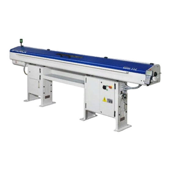
2 - TECHNICAL INFORMATION Elite112_220_Evo_SIII BAR FEEDER GENERAL DESCRIPTION The ELITE automatic bar feeder is used in the machine-tool industry and in particular, for automatic lathe feeding. It is particularly suitable for feeding fixed or sliding headstock lathes, numerical control or cam lathes. The operating cycle is controlled by a PLC, integrated in the electrical control panel, which is able to communicate with the lathe control system. - Page 19 2 - TECHNICAL INFORMATION Elite112_220_Evo_SIII • MAIN PARTS A MOTOR; moves the bar pusher. B SOLENOID VALVE UNIT; sends signals to the pneumatic components. C BAR POSITIONING DEVICE; allows finding the bar loading position on the magazine rack. D MAGAZINE WITH PILGRIM STEP; stores the bars. E LUBRICATION PUMP;...
- Page 20 2 - TECHNICAL INFORMATION Elite112_220_Evo_SIII N OPENING/CLOSING PNEUMATIC CYLINDER; to provide motion to the pneumatic devices that allow the lower guide channel opening/closing for the remnant drop. O MOTOR DRIVE; opens and closes the guide channels. P UPPER GUIDE CHANNELS; drive the bar during the machining. Q LOWER GUIDE CHANNELS;...
-
Page 21: Pneumatic System - Main Components
2 - TECHNICAL INFORMATION Elite112_220_Evo_SIII 2.1.1 Pneumatic system - Main components A - REGULATOR FILTER GROUP B - FACING CYLINDER C - PNEUMATIC CLAMP CYLINDER D - UPPER GUIDE CHANNEL OPENING / CLOSING CYLINDER – REMNANT DROP F - REGULATOR G - SOLENOID VALVE UNIT H - BAR SELECTION UNIT (for Elite 220 only) I - BUSHING DRIVE UNIT (Optional - for Elite 220 only) -
Page 22: Operating Cycle
2 - TECHNICAL INFORMATION Elite112_220_Evo_SIII OPERATING CYCLE In the automatic operation mode, bar feeder movements are controlled in the sequence described below. The bar-pusher (A) feeds bar (B) in the lathe by following lathe impulses until bar end. The bar-pusher (A) and remnant (C) are in their forwards limit stop position. - Page 23 2 - TECHNICAL INFORMATION Elite112_220_Evo_SIII Clamps (D) close again to perform remnant (C) extraction check. If the remnant is still inserted in the bar pusher collet, the bar feeder stops; otherwise, it continues its cycle. Bar Drop from the Horizontal Rack (Pilgrim Step Magazine) Upper guide channels (H) open, magazine bar feeding device (F) rises and lifts first bar (G)
- Page 24 2 - TECHNICAL INFORMATION Elite112_220_Evo_SIII The first feeding carriage (M) starts its stroke When the first feeding carriage (M) completes its stroke, the required space has been created for bar-pusher insertion. The first feeding carriage performs the return stroke. The upper guide channels (H) close; the bar pusher (A) is positioned along the spindle axis.
- Page 25 2 - TECHNICAL INFORMATION Elite112_220_Evo_SIII The bar pusher (A) and bar (G) carry out their facing stroke. A new automatic working cycle is started. 2 - Pag. 9 / 9...
-
Page 26: Machine Phases - Status Of Cycle Control Sensors
2 - TECHNICAL INFORMATION Elite112_220_Evo_SIII 2.2.1 MACHINE PHASES - Status of cycle control sensors PHASE-0 BAR MACHINING A12M_02_026_00 After feeding a long bar (equal to, or slightly shorter than the magazine length) and after the facing phase. The active rack sensors are sensors number 3 and number 4. - Page 27 2 - TECHNICAL INFORMATION Elite112_220_Evo_SIII Following the same sequence, when the bar pusher moves forwards, the guide channel control cam opens the third guide channel stopping on sensors 6+4. A12M01_02_026a_00_6_4 Following the same sequence, when the bar pusher moves forwards, the guide channel control cam opens the fourth guide channel stopping on sensors 7+4.
- Page 28 2 - TECHNICAL INFORMATION Elite112_220_Evo_SIII Following the same sequence, when the bar pusher moves forwards, the guide channel control cam opens the fifth guide channel stopping on sensors 8+4. A12M01_02_026a_00_8_4 Following the same sequence, when the bar pusher moves forwards, the guide channel control cam opens the sixth guide channel stopping on sensors 9.
- Page 29 2 - TECHNICAL INFORMATION Elite112_220_Evo_SIII PHASE-1 BAR PUSHER RETURN A12M_02_027_00 The bar change phase starts and the bar pusher moves back to the removal/feeding value. During the return stroke, guide channels 1, 3, 4, 5 and 6 progressively close by performing the opening procedure in reverse order until the preset values are reached.
- Page 30 2 - TECHNICAL INFORMATION Elite112_220_Evo_SIII PHASE-2/3/4/5/6/7 CLAMP CLOSING - REMNANT REMOVAL - CLAMP OPENING AFTER REMOVAL - CLAMP CLOSING FOR REMNANT CHECK - CLAMP OPENING AFTER REMNANT CHECK - ZERO AXIS A12M_02_028_00 When working in removal mode, the pneumatic clamps close and hold the bar;...
- Page 31 2 - TECHNICAL INFORMATION Elite112_220_Evo_SIII PHASE-8/9 GUIDE CHANNEL FULL OPENING - BAR FEEDING A12M_02_029_00 The guide channel control cam moves until it switches on sensor number 2, which is the only active sensor. All four guide channels open. The magazine performs a step and a new bar is fed into the guide channel.
- Page 32 2 - TECHNICAL INFORMATION Elite112_220_Evo_SIII PHASE-10/11/12 GUIDE CHANNEL PARTIAL CLOSING - BAR FIRST FEEDING - RETURN AFTER FIRST FEEDING A12M_02_030_00 The guide channel control cam moves until it switches on sensor number 1, which is the only active sensor. After the Feeding/Removal clamp device the guide channels close.
- Page 33 2 - TECHNICAL INFORMATION Elite112_220_Evo_SIII PHASE-13/14/15/16 GUIDE CHANNEL AND CLAMP CLOSING - FEEDING - CLAMP WORK POSITION - FACING A12M_02_031_00 The guide channel control cam moves until it switches on sensors 3 and 4, which are the only active ones. All guide channels close and also the clamps close to lock the bar;...
-
Page 34: Safety Devices
2 - TECHNICAL INFORMATION Elite112_220_Evo_SIII SAFETY DEVICES A12M_02_003_01 A EMERGENCY BUTTON; when pressed, all bar feeder and lathe functions are stopped in an emergency condition. C SLIDING GUARD: linked to microswitch C1. according to the cycle setting, its functions are: manual cycle;... - Page 35 2 - TECHNICAL INFORMATION Elite112_220_Evo_SIII A12M_02_003_01 D FIXED GUARD: it is made of transparent material to allow visual inspection of the bar magazine area. H REMNANT RECOVERY BOX: it also acts as a fixed guard to prevent accidental access to moving parts.
-
Page 36: Safety Plates - Location And Description
2 - TECHNICAL INFORMATION Elite112_220_Evo_SIII SAFETY PLATES - LOCATION AND DESCRIPTION The figure indicates the position of the signals put on the bar feeder. A12M_02_004_00 MAX. A- Risk of crushing your arms: do not put hands inside when there are components in motion. B- Do not remove guards: it is forbidden to use the bar feeder without the guards installed and in operating conditions. -
Page 37: Version Description
2 - TECHNICAL INFORMATION Elite112_220_Evo_SIII VERSION DESCRIPTION Maximum - minimum bar length Maximum length Minimum length Model Version mm (ft) 3200 (10,5 ft) 1200 Elite 3700 (12 ft) 1200 Max. bar pusher extension A –Max. Model Version Version extension(mm) Elite 32 - 37 1200 1485... -
Page 38: Technical Data
2 - TECHNICAL INFORMATION Elite112_220_Evo_SIII TECHNICAL DATA 76,5 A12M_02_001_00_220 Overall dimensions 32, 37. Model Version A (mm) B (mm) C (mm) H (mm) 3788 1114 900-1200 Elite 4358 1635 900-1200 2 - Pag. 22 / 22... - Page 39 2 - TECHNICAL INFORMATION Elite112_220_Evo_SIII General technical data Elite 220 Evo Round bar size Ø min. 2 mm (5/64”) Ø max 20 mm (25/32”) Hexagonal bar size (key socket) min.1,7 mm max17 mm Mod. 32 - 3200 Maximum bar length Mod.37 –...
- Page 40 2 - TECHNICAL INFORMATION Elite112_220_Evo_SIII General technical data Elite 112 Evo Round bar size Ø min. 1 mm (3/64”) Ø max 12,7 mm (1/2”) Hexagonal bar size (key socket) min.1,7 mm max11 mm (9/16”) Mod. 32 - 3200 Maximum bar length Mod.37 –...
- Page 41 2 - TECHNICAL INFORMATION Elite112_220_Evo_SIII Working axis height Y (mm) Z (mm) X (mm) Lower screw Pilgrim step Magazine with Model Working axis position magazine sloped rack height max. loading height max.loading height 905÷945 1065 940÷980 1100 975÷1015 1030 1135 1010÷1050 1065 1170...
- Page 42 2 - TECHNICAL INFORMATION Elite112_220_Evo_SIII ELITE guide channel lubricating oils ISO/UNI Brand Name rating Agip Acer 32 Api Cis 32 Energol CS 32 Castrol Magna 32 Chevron Circulating Oil 32 Movixa 32 Esso Nuto 32 Fina Solna 32 IP Hermea 32 CLASSE C Klüber Crucolan 32...
-
Page 43: Noise Levels
2 - TECHNICAL INFORMATION Elite112_220_Evo_SIII 2.6.1 Noise levels The bar feeder does not cause acoustic noise. The noise occurs when the lathe, to which the bar feeder is connected, is working and the bar is rotating into the bar feeder guide channels. In this case, the noise level depends on the following conditions: •... -
Page 44: Device For Sliding Headstock Lathes - Foreword
2 - TECHNICAL INFORMATION Elite112_220_Evo_SIII DEVICE FOR SLIDING HEADSTOCK LATHES - FOREWORD This bar feeder has been designed and manufactured to be coupled to sliding headstock lathes too. To this purpose, the following special device is available. 2.7.1 Axial displacement device (Optional) - Description It allows the bar feeder to be moved away from the lathe to allow maintenance, cleaning or any other servicing of the lathe. -
Page 45: Bar/Headstock Synchronization Device - Description
2 - TECHNICAL INFORMATION Elite112_220_Evo_SIII 2.7.2 Bar/headstock synchronization device - Description It is used to connect the bar-pusher (and consequently, the bar) to the lathe headstock, to obtain their synchronized forwards/backwards movement. 2 - Pag. 29 / 29... -
Page 46: Diaphragm Bushing Device Optional (For Elite 220 Only) - Description
2 - TECHNICAL INFORMATION Elite112_220_Evo_SIII 2.7.3 Diaphragm bushing device OPTIONAL (for Elite 220 only) - Description This device, attached to the front of the bar feeder, reduces bar vibration to a minimum by keeping the bar centered during rotation. It uses three diaphragms, which, when closed, form a semi- circular channel with a diameter slightly larger than that of the bar being machined. -
Page 47: Telescopic Front Nose - Description
2 - TECHNICAL INFORMATION Elite112_220_Evo_SIII 2.7.4 Telescopic front nose - Description A12M_05_03_02_02s It is used to optimize bar guiding between the front portion of the bar feeder and the lathe spindle, example with diaphragm bush (for Elite 220 only). Example Elite 112 Evo Maximum stroke and overall dimension Max stroke Overall dimensions... -
Page 48: Devices For Cam Lathes - Foreword
2 - TECHNICAL INFORMATION Elite112_220_Evo_SIII DEVICES FOR CAM LATHES - FOREWORD This bar feeder has been designed and manufactured to be coupled to cam lathes too. To do this, special devices are available which are listed and then described below. 2.8.1 Cam box - Description Used to synchronize the bar feeder and cam lathe... - Page 49 3 - SAFETY – GENERAL INFORMATION Elite112_220_Evo_SIII INDEX GENERAL SAFETY REGULATIONS ................2 HANDLING AND INSTALLATION - Safety ..............3 ADJUSTMENTS AND SETUP - Safety ................3 USE AND OPERATION - Safety .................. 4 BAR FEEDER MAINTENANCE - Safety ................ 4 EC DECLARATION OF CONFORMITY .................
-
Page 50: General Safety Regulations
Strictly comply with the health and safety regulations at work issued by the relevant authorities in each country. • IEMCA declines any liability for injury to persons or damage to property if the relevant safety regulations are disregarded. • The bar feeder must only be used for the procedures indicated by IEMCA: no other improper use is allowed. -
Page 51: Handling And Installation - Safety
3 - SAFETY – GENERAL INFORMATION Elite112_220_Evo_SIII HANDLING AND INSTALLATION - Safety • The bar feeder must be handled using suitable means and methods only. • Do not stand or transit underneath a suspended load, or within the range of action of the crane, lift truck or other suitable lifting and transport means. -
Page 52: Use And Operation - Safety
• Keep drain oil in suitable containers and deliver it to companies specialized in the storage and disposal of polluting waste products. • Avoid environmental pollution. • Use original IEMCA spare parts only. 3 - Pag. 4 / 4... -
Page 53: Ec Declaration Of Conformity
(2006/42/ EC Regulation, Enclosure II, Part A) Mr. TOMASO TAROZZI, acting as MANAGING DIRECTOR CEO and delegated by the company I G M I S.p.A. DIVISIONE IEMCA with legal office and establishment in Via Granarolo, 167 – 48018 FAENZA (RA) as manufacturer,... -
Page 54: General Description Of Supply
Should the bar feeder be used together with machine tools that do not have the CE marking, Iemca reminds to their clients that they should assess if the device is in compliance with Directive 2009/104/EC and subsequent amendments even after installing the bar feeder. -
Page 55: Residual Risks
3 - SAFETY – GENERAL INFORMATION Elite112_220_Evo_SIII RESIDUAL RISKS • The following residual risks exist: PNEUMATIC POWER Presence of pneumatic energy in the supply system to the machine actuators. Here are some examples of the warnings referenced above: Before doing regular maintenance or any other service on the machine pneumatic actuators it is essential to stop the pneumatic energy supply by disconnecting the supply hose (see chapter 4). - Page 56 3 - SAFETY – GENERAL INFORMATION Elite112_220_Evo_SIII 1)Bush replacement or maintenance work inside the bushing holding equipment should only be performed after switching the bar feeder off. 2)With the bar feeder in automatic mode, there is a potential crushing risk if you reach your hands and arms into the guide channel area (bar pusher movement).
- Page 57 3 - SAFETY – GENERAL INFORMATION Elite112_220_Evo_SIII BAR FEEDER FASTENING IN AN UNSTEADY EQUILIBRIUM 1) If during installation the floor proves not to be level, the authorized technician will level out and align the bar feeder using the levelling screws of the fastening plates in the outer part of the bar feeder and in the anti-vibration plugs in the inner part.
- Page 58 3 - SAFETY – GENERAL INFORMATION Elite112_220_Evo_SIII FIXED GUARDS If you have removed some fixed guards in order to be able to perform maintenance on the bar feeder, put them back in place and secure them soon after completing your work. Make sure they are secured so as to prevent access to moving parts during work.
- Page 59 3 - SAFETY – GENERAL INFORMATION Elite112_220_Evo_SIII 1)The colour loses intensity. 2)Other pieces of equipment or panels placed too close to the warning lamps on the bar feeder. THERE ARE CIRCUITS NOT INTERRUPTED BY THE DISCONNECTING DEVICE There is danger caused by voltages from the lathe signals that are not interrupted by disconnectors in the bar feeder.
-
Page 60: Foreseeable Misuses
3 - SAFETY – GENERAL INFORMATION Elite112_220_Evo_SIII FORESEEABLE MISUSES • Do not tamper with the machine's safety devices (for example, the safety microswitches of the openable guard to access the bar magazine) • Do not use the lubrication pump for other purposes (for example, to pour different liquids) •... - Page 61 4 - HANDLING AND INSTALLATION Elite112_220_Evo_SIII INDEX PACKAGING ...................... 3 4.1.1 BAR SUPPORT DISASSEMBLING ................3 LIFTING ......................3 INSTALLATION AREA - FEATURES (with and without displacement) ..... 5 BAR FEEDER - INSTALLATION ................6 4.4.1 Backing plates and support feet - Installation ............. 6 4.4.2 Height - Adjustment ....................
- Page 62 4 - HANDLING AND INSTALLATION Elite112_220_Evo_SIII 4.8.3 FUNCTION SIGNALS ....................26 PNEUMATIC DEVICE LAYOUT .................. 27 4.9.1 PNEUMATIC CONNECTION ................30 4.10 MACHINING PARAMETERS SETTING ..............32 4.11 BAR FEEDER TESTING ..................32 4 - Pag. 2 / 2...
-
Page 63: Packaging
4 - HANDLING AND INSTALLATION Elite112_220_Evo_SIII PACKAGING There are three possible bar feeder packaging: A WITHOUT PACKAGING. B WITH PALLET: the bar feeder is placed on a pallet and wrapped with protective film. C WITH CRATE: the bar feeder is contained in a crate and wrapped with protective film. 4.1.1 BAR SUPPORT DISASSEMBLING WARNING - CAUTION:... - Page 64 4 - HANDLING AND INSTALLATION Elite112_220_Evo_SIII According to the packaging choice, lifting is carried out as shown in the next page. LIFTING WITH NO PACKAGING • Insert the four eyebolts into the plates inside the bar feeder foot, as shown in the picture. •...
-
Page 65: Installation Area - Features (With And Without Displacement)
4 - HANDLING AND INSTALLATION Elite112_220_Evo_SIII INSTALLATION AREA - FEATURES (with and without displacement) The floor should be stable and levelled to guarantee good fastening to the ground. Provide an area of suitable dimensions according to the type of bar feeder used. The areas (D) (work area), (E) (bar feeding area) and (F) (remnant ejection area) should be properly delimited to prevent collisions between the operator and any handling equipment or transport vehicles travelling near the bar feeder. -
Page 66: Bar Feeder - Installation
4 - HANDLING AND INSTALLATION Elite112_220_Evo_SIII BAR FEEDER - INSTALLATION Before carrying out the bar feeder installation, check the lathe stability; make sure that it is firmly fixed to the ground and that the spindle axis is perfectly in horizontal position. 4.4.1 Backing plates and support feet - Installation •... -
Page 67: Preliminary Positioning
In fixed headstock lathes, its stroke can be reduced to 100 mm to allow the bar feeder to be brought as close as possible to the lathe; contact IEMCA After-sales Service for more information. 4 - Pag. 7 / 7... -
Page 68: Front Nose - Installation
4 - HANDLING AND INSTALLATION Elite112_220_Evo_SIII • Roughly adjust the height of the working axis and the alignment with the lathe by turning the screws of the support feed. A12M_04_016a_00 4.4.4 Front nose - Installation ELITE • Install the front nose (A) on the front plate. •... -
Page 69: Levelling And Alignment
4 - HANDLING AND INSTALLATION Elite112_220_Evo_SIII 4.4.5 Levelling and alignment FOREWORD Alignment between the bar feeder and lathe is the most critical installation phase; therefore, this operation should be carried out by experienced personnel with the greatest accuracy. WARNING - CAUTION: an error during the alignment may be the major cause of a bad operation of the bar feeder and of its consequent... - Page 70 4 - HANDLING AND INSTALLATION Elite112_220_Evo_SIII LEVELLING • Check oil levelling by positioning the level crosswise and lengthwise on the supports of the lower guide channel. • Carry out the required modifications by turning the screws (A) on the support feet 4 - Pag.
- Page 71 4 - HANDLING AND INSTALLATION Elite112_220_Evo_SIII 4.4.6 ALIGNMENT • Insert the supplied (CH8) wrench in the intermediate drive shaft and move the bar pusher to its backwards limit stop. • To access the shaft you need to remove the protection guard (A). •...
- Page 72 4 - HANDLING AND INSTALLATION Elite112_220_Evo_SIII • Loosen screw (C). • Leave screw (E) to support the guard; the microswitch (D) is now free and the display shows the message "18 Error: Bar Feeder Emergency" (see instruction manual). 4 - Pag. 12 / 12...
- Page 73 4 - HANDLING AND INSTALLATION Elite112_220_Evo_SIII • Insert the wrench into the guide channel opening shaft and open the upper guide channels. To obtain alignment lead a (ø 1 mm) nylon thread between the lathe collet and the bar feeder rear plate, then proceed as follows: •...
- Page 74 4 - HANDLING AND INSTALLATION Elite112_220_Evo_SIII • check with a sliding caliper, the alignment near bushing (C) and spindle (D); use a tolerance of ± 0.15 mm in the four directions. • prepare a perfectly straight ground bar, with an external diameter equal to the maximum spindle bar passage and with a length equal to the double coupling distance (see (B) in the “Preliminary Positioning”...
- Page 75 4 - HANDLING AND INSTALLATION Elite112_220_Evo_SIII POSITIONING ADJUSTMENTS After checking the alignment of the bar feeder with either the thread or the bar, any required corrections should be carried out. Adjust height by turning the screws in the support feet; carry out lateral adjustments with calibrated mallet blows on the sides of plates (E).
-
Page 76: Bar Feeder Fastening
Wherever possible, the bar feeder should be fixed to the lathe with a suitable coupling unit according to lathe brand and type. The figure shows a general example of fixing; contact IEMCA service department for more information. 4 - Pag. 16 / 16... -
Page 77: Device For Sliding Headstock Lathes - Installation
Bar-headstock synchronization device • Open the upper guard. INFORMATION: the figure shows a general example of installation; contact IEMCA service department for more information. • Loosen screw (A). • Install the bar (B) and tie-rod (C) and make sure that the headstock (D) can run freely throughout its stroke together with shaft (E). -
Page 78: Telescopic Front Nose - Installation
4 - HANDLING AND INSTALLATION Elite112_220_Evo_SIII 4.5.2 Telescopic front nose - Installation If the bar feeder is equipped with a telescopic front nose, proceed as described below. • Remove the fixed front nose that had been installed to obtain alignment between the bar feeder and the lathe. -
Page 79: Devices For Cam Lathes - Installation
DEVICES FOR CAM LATHES - INSTALLATION 4.6.1 Cam box INFORMATION: the figure shows a general example of installation; contact IEMCA service department for more information. • Install the sleeve (A) on the lathe camshaft (B). • Connect the shaft (C) to the sleeve through the pin (D). -
Page 80: Camshaft Release Device
Elite112_220_Evo_SIII 4.6.2 Camshaft release device INFORMATION: the figure shows a general example of installation; contact IEMCA service department for more information. Radial version • Mount the articulation (A) in the flange (B). • Mount the joint (C) in the articulation (D) and in the lathe control (E). - Page 81 4 - HANDLING AND INSTALLATION Elite112_220_Evo_SIII Axial version • Drill and thread the lathe housing to fix the transmission unit (F). • Fit disc (G) to control (H). • Insert shaft (L) into joint (M) and fix it using a pin (O).
-
Page 82: Lubrication Oil - Filling
4 - HANDLING AND INSTALLATION Elite112_220_Evo_SIII LUBRICATION OIL - FILLING WARNING - CAUTION: wear personal protections according to the regulations in force. • Open the rear base door and pour oil into the tank. • Check the level by means of the indicator (A). See §... -
Page 83: Electrical Connection
4 - HANDLING AND INSTALLATION Elite112_220_Evo_SIII ELECTRICAL CONNECTION DANGER - WARNING: this type of operation should only be entrusted to skilled personnel with precise technical competence and specific abilities to comply with the applicable standards and regulations in force. DANGER - WARNING: the bar feeder must be electrically connected to the lathe, which in turn, must be connected to the plant electrical installation in compliance with the applicable regulations in force. -
Page 84: 4.8.2.1 Emergency Stop
4 - HANDLING AND INSTALLATION Elite112_220_Evo_SIII 4.8.2.1 EMERGENCY STOP 4 emergency channels are available, 2 from bar feeder to lathe and 2 from lathe to bar feeder. · Emergency from bar feeder to lathe (2 channels, contacts off = Emergency activated). - Page 85 4 - HANDLING AND INSTALLATION Elite112_220_Evo_SIII DANGER-WARNING!!! 4 - Pag. 25 / 25...
-
Page 86: Function Signals
4 - HANDLING AND INSTALLATION Elite112_220_Evo_SIII DANGER - WARNING: The bar feeder safety depends on these connections, therefore IEMCA is not responsible for any possible damage to persons or things, caused by improper use of the above mentioned signals. 4.8.3 FUNCTION SIGNALS The bar feeder can send and receive all the signals which are necessary to its correct operation. -
Page 87: Pneumatic Device Layout
4 - HANDLING AND INSTALLATION Elite112_220_Evo_SIII PNEUMATIC DEVICE LAYOUT ABBREVIATION DESCRIPTION FUNCTION Controls the clamp opening and Cylinder closing. Controls the upstroke of the Cylinder remnant drop lower guide channel. Controls the upstroke of the Cylinder remnant drop upper guide channel. - Page 88 4 - HANDLING AND INSTALLATION Elite112_220_Evo_SIII ABBREVIATION DESCRIPTION FUNCTION Controls the bar lifting plate Cylinder upstroke and downstroke. Controls the fore bush opening Cylinder and closing. Dispenses and adjusts the supply Distributor + flow inside the pneumatic pressure switch system. Cylinder or piston control device Solenoid valve (see description Solenoid valve...
- Page 89 4 - HANDLING AND INSTALLATION Elite112_220_Evo_SIII ABBREVIATION DESCRIPTION FUNCTION Remnant drop upper guide channel Remnant drop solenoid valve opening/closing Bar lifting upstroke control Bar selection plate upstroke-downstroke solenoid valve (**) Fore bush control solenoid valve Fore bush opening-closing (*) (**) Clamp device control solenoid Clamp device closing valve...
-
Page 90: Pneumatic Connection
4 - HANDLING AND INSTALLATION Elite112_220_Evo_SIII 4.9.1 PNEUMATIC CONNECTION • Connect the pipe with Ø 8 of the pneumatic network to the quick coupling connection (A). Install an upstream 3-way cock to perform the sectioning and the pressure release. With knob (B), adjust the pressure at 6 bar. - Page 91 4 - HANDLING AND INSTALLATION Elite112_220_Evo_SIII 4.9.2 BAR FEEDER HANDLING WITHOUT POWER SUPPLY Without power supply or in case of an emergency it is possible to move the pneumatic units using the solenoid valves manually: keep button (A) pressed; using a small screwdriver press the buttons (B), present on the individual solenoid valves, to move the unit.
-
Page 92: Machining Parameters Setting
4 - HANDLING AND INSTALLATION Elite112_220_Evo_SIII 4.10 MACHINING PARAMETERS SETTING By means of a handheld keyboard you can assign the different parameter values according to the operating characteristics of lathe - bar feeder coupling and to the working needs. See the "Keyboard instruction manual" to assign adequate values. 4.11 BAR FEEDER TESTING INFORMATION:... - Page 93 5 - ADJUSTMENT AND SETUP Elite112_220_Evo_SIII INDEX ADJUSTMENT AND SETUP - FOREWORD ............2 GENERAL ADJUSTMENTS - FOREWORD .............. 2 5.2.1 Feed chains - Adjustment ..................3 5.2.2 Pressure switch - Adjustment ..................4 SETUP ACCORDING TO THE BAR TO BE MACHINED ..........5 5.3.1 Guide channels, half bushes, bar pusher and collet - Replacement ......
-
Page 94: Adjustment And Setup - Foreword
5 - ADJUSTMENT AND SETUP Elite112_220_Evo_SIII ADJUSTMENT AND SETUP - FOREWORD DANGER - WARNING: do not perform any adjustment when the bar feeder is running unless expressly requested in the manual. In addition to normal adjustments throughout its service life, this bar feeder also needs set-up according to the type of operation. -
Page 95: Feed Chains - Adjustment
5 - ADJUSTMENT AND SETUP Elite112_220_Evo_SIII 5.2.1 Feed chains - Adjustment After operating the bar feeder for some hours you should always check the tensioning of the bar pusher feeding chains. The chains must be adjusted as follows: • loosen two nuts (B) and two screws (C); •... -
Page 96: Pressure Switch - Adjustment
5 - ADJUSTMENT AND SETUP Elite112_220_Evo_SIII 5.2.2 Pressure switch - Adjustment After unscrewing the glass protection, the pressure switch can be properly adjusted by turning the relevant adjusting screw (A). Proper setting is 4.5 bar (0.45 MPa). WARNING - CAUTION: Do not further turn anticlockwise when the green pointer is on 0. -
Page 97: Setup According To The Bar To Be Machined
5 - ADJUSTMENT AND SETUP Elite112_220_Evo_SIII SETUP ACCORDING TO THE BAR TO BE MACHINED According to the "new" diameter of the bar to be machined, a few or several operations must be carried out based on the diameter of the previously machined bar. The table (regarding the ELITE guide channel, bar pusher, bar and pipe diameter) reports the diameters of available guides as well as the range of the bar pushers that can be assembled, and the diameters of the bar to be machined. - Page 98 5 - ADJUSTMENT AND SETUP Elite112_220_Evo_SIII WARNING - CAUTION: barstock diameters for any guide channel are only given as an indication. A diameter of a bar to be machined approximately 6 mm smaller than the guide channel diameter may cause vibration and failure to the bar feeder. Therefore, it may be necessary to slow down the bar rotation speed or to change the guide channel diameter in order to obtain the best performance for a specific application.
-
Page 99: Guide Channels, Half Bushes, Bar Pusher And Collet - Replacement
5 - ADJUSTMENT AND SETUP Elite112_220_Evo_SIII 5.3.1 Guide channels, half bushes, bar pusher and collet - Replacement • When the magazine is empty (no bars) set the feeder to manual mode • Press on the keyboard or use the socket A12M_05_003_00_112EVO screw key to bring the bar pusher backwards to its limit stop. - Page 100 5 - ADJUSTMENT AND SETUP Elite112_220_Evo_SIII • Remove and replace the bar pusher. INFORMATION: case setup (lathe-bar feeder), the bar feeder supports (F) and the first feeding device (G) must not be replaced, even when changing the bar feeder diameter. A12M_05_004_01 •...
- Page 101 5 - ADJUSTMENT AND SETUP Elite112_220_Evo_SIII Telescopic front nose • Remove front nose(C). • Remove the internal front nose. • If necessary, remove the lathe spindle liner and install another one suitable for the diameter of the guide channel. 5 - Pag. 9 / 9...
- Page 102 Choose the right collet for the bar; refer to the "GUIDE CHANNELS - BAR PUSHERS - REVOLVING TIPS - COLLETS" selection chapter. INFORMATION: contact IEMCA service department for further information. Legend: 4 Quick coupling collet for bars To facilitate the bar entry into the lathe collet, if the diameter of the bars to be machined is <...
-
Page 103: Diaphragm Bushing Device - Description (For Elite 220 Only)
5 - ADJUSTMENT AND SETUP Elite112_220_Evo_SIII 5.3.2 Diaphragm bushing device - Description (for Elite 220 only). The diaphrgram bushing device (optional) should be adjusted according to the bar diameter. Perform the operations described below with the open and active cylinder (D) (under pressure). Loosen the nut (A) and adjust the screw (B) A12M_05_03_02_00s until the index (C) reaches the diameter of the... - Page 104 5 - ADJUSTMENT AND SETUP Elite112_220_Evo_SIII 5.3.3 Telescopic front nose adjustment TELESCOPIC FRONT NOSE (STROKE 120/160) When replacing the telescopic front nose, it is not necessary to change completely the unit, but only some parts supplied with the spare parts kit. •...
-
Page 105: Front Nose - Replacement
5 - ADJUSTMENT AND SETUP Elite112_220_Evo_SIII 5.3.4 Front nose - Replacement With diaphragm bushing device (for Elite 220 only) • Remove the oil recovery device (C). • Loosen grub screws (D). • Replace the front nose (A) with another front nose suitable for the bar. Length (B) must cover the distance between the bar feeder and the lathe. -
Page 106: Cam Box - Timing
5 - ADJUSTMENT AND SETUP Elite112_220_Evo_SIII CAM BOX - TIMING If the bar feeder is equipped with a cam box, each cam should be timed to its own microswitch. The timing procedure is as follows. MICROSWITCH FUNCTION S90 - Bar feeding enabling signal It controls the bar feeding motor start/stop. - Page 107 5 - ADJUSTMENT AND SETUP Elite112_220_Evo_SIII CAM TIMING LATHE CAM COMPLETE CYCLE PHASE HEADSTOCK PHASE COLLET LATHE BAR FEEDER CAM COMPLETE CYCLE PHASE MICROSWITCH PHASE MICROSWITCH PHASE MICROSWITCH A STROKE CLOSED B FEEDING OPEN C FORWARD STOP CLOSED D RETURN DISABLED E BACKWARD STOP DISABLED...
- Page 108 5 - ADJUSTMENT AND SETUP Elite112_220_Evo_SIII Microswitches S90 and S91 • Rotate manually shaft (A) up to a distance of 10° approx. from the collet opening, then “S90” microswitch cam until wheel (B) is released. • Turn shaft (A) until the collet opens. •...
-
Page 109: Bar Support Assembly
5 - ADJUSTMENT AND SETUP Elite112_220_Evo_SIII Microswitch S92 • Rotate manually shaft (A) until the headstock starts its return stroke with closed collet. • Release the "S92" microswitch wheel. • Continue rotation until the headstock has completed its return stroke. •... -
Page 110: Removal/Feeding Clamp Device - Adjustment
5 - ADJUSTMENT AND SETUP Elite112_220_Evo_SIII Removal/Feeding clamp device - Adjustment This operation, that is usually not necessary, allows to change vertically the bar position during the feeding phase. It is necessary if bar pushers with reduced diameter are used (e.g. guide channel D=24mm and bar pusher D=22.5mm). -
Page 111: Sloped Rack Magazine Enabling (For Elite 220 Only)
5 - ADJUSTMENT AND SETUP Elite112_220_Evo_SIII Sloped rack magazine enabling (for Elite 220 only) To activate the "Sloped Rack Magazine" and deactivate the "Pilgrim Step Magazine" follow the procedure described below. Loosen the handle (A) at the end of the bar magazine. -
Page 112: Sloped Rack Magazine Disabling (For Elite 220 Only)
5 - ADJUSTMENT AND SETUP Elite112_220_Evo_SIII 5.7.1 Sloped rack magazine disabling (for Elite 220 only) To disable the Sloped Rack magazine and activate the Pilgrim Step magazine follow the procedure described below. Loosen the handle (A) at the end of the bar magazine. -
Page 113: Bar Guide Plates And Bar Selectors - Adjustment (For Elite 220 Only)
5 - ADJUSTMENT AND SETUP Elite112_220_Evo_SIII 5.7.2 Bar guide plates and bar selectors - Adjustment (for Elite 220 only) Bar guide plate adjustment Loosen the handle (A) and lift the backing plate (B) to create the space for inserting the bar (if necessary). - Page 115 6 - USE AND OPERATION Elite112_220_Evo_SIII INDEX PRELIMINARY NOTE ON USE AND OPERATION ............2 CONTROL DESCRIPTION ..................2 KEYBOARD CONTROL DESCRIPTION ................. 5 LIGHT INDICATOR DESCRIPTION ................9 BARS TO BE MACHINED - FEATURES AND PREPARATION ........10 6.5.1 BAR TO BE MACHINED - SOLID BARS ..............
-
Page 116: Preliminary Note On Use And Operation
6 - USE AND OPERATION Elite112_220_Evo_SIII PRELIMINARY NOTE ON USE AND OPERATION INFORMATION: the incidence of injuries cased by the use of machines, depends on many factors that cannot always be prevented and checked. Some accidents can depend on some unpreventable environmental factors, others can be especially due to the operators' behaviour. - Page 117 6 - USE AND OPERATION Elite112_220_Evo_SIII The illustration shows the position of the electrical controls and the keyboard controls. A12G220_01_001_00 1 MAIN SWITCH: turns the power supply on and off. Position 0 (OFF) the machine is not powered. Position I (ON) the machine is powered. 5 EMERGENCY STOP PUSH-BUTTON: stops the bar feeder in case of emergency.
- Page 118 6 - USE AND OPERATION Elite112_220_Evo_SIII 6 - Pag. 4 / 4...
-
Page 119: Keyboard Control Description
6 - USE AND OPERATION Elite112_220_Evo_SIII KEYBOARD CONTROL DESCRIPTION It stops the bar feeder: for restart, manually release the push-button. 2 Start buttons: opposite buttons enabling the keys for some functions. Press both buttons and simultaneously the button corresponding to the desired function. - Page 120 6 - USE AND OPERATION Elite112_220_Evo_SIII 13 Selects the keyboard modes: with LED off ; selects the "message display" mode. with LED on ; selects the "parameter display" mode. 14 Multifunction Selects the next parameter Moves the selection cursor rightwards. 15 Sets the carriage movement motor.
- Page 121 6 - USE AND OPERATION Elite112_220_Evo_SIII 21 Multifunction Sets the numerical value. Moves the bar pusher at a low speed. 22 Multifunction Sets the font. Moves the bar pusher at a high speed. 23 Sets the comma. 24 Multifunction Sets the numerical value. Opens the guide channels.
- Page 122 6 - USE AND OPERATION Elite112_220_Evo_SIII 27 Multifunction Sets the numerical value. Recalls the main menu (MAIN MENU). 28 Multifunction Sets the numerical value. Moves the bar pusher at a low speed. 29 It moves the bar pusher at high speed. 30 Multifunction Stops the selection function.
-
Page 123: Light Indicator Description
6 - USE AND OPERATION Elite112_220_Evo_SIII LIGHT INDICATOR DESCRIPTION Green light: Signals that the bar feeder is working in automatic mode. Red light (OPT): signals that the bar feeder is in stopping conditions, or that it is working in manual mode. -
Page 124: Bars To Be Machined - Features And Preparation
6 - USE AND OPERATION Elite112_220_Evo_SIII BARS TO BE MACHINED - FEATURES AND PREPARATION WARNING - CAUTION: do not load bars having sizes different from those recommended by the manufacturer (see reference table in § “VERSION DESCRIPTION”, Chap. 2). Clean the bar surface before loading bars. INFORMATION: the bar must not have a straightness defect above 0.5 per 1,000. - Page 125 6 - USE AND OPERATION Elite112_220_Evo_SIII When machining bars having a diameter equal to or only slightly smaller than the bar pusher diameter, it is necessary to turn the bar rear ends; diameter "D" should be suitable for the collet installed in the bar pusher.
- Page 126 6 - USE AND OPERATION Elite112_220_Evo_SIII If the bars to be machined have a diameter equal to or only slightly smaller than the bar- pusher diameter, without replacing the guide channels and the bar feeder, bar rear ends should be machine-turned to allow the collet hold.
-
Page 127: Barstock - Pipes
6 - USE AND OPERATION Elite112_220_Evo_SIII 6.5.2 BARSTOCK - PIPES If pipes have to be machined, their rear ends should be chamfered as shown in the figure. 6 - Pag. 13 / 13... -
Page 128: Bar Straightness - Measurement
6 - USE AND OPERATION Elite112_220_Evo_SIII 6.5.3 BAR STRAIGHTNESS - Measurement The bar vibrations are partially due to the state of the bar itself: if the bar is not perfectly straight, it can cause vibrations. Round bars As stated also in the UNI-10233/2 regulation, the bar straightness can be measured by positioning the bar on two V-supports and controlling its straightness. - Page 129 6 - USE AND OPERATION Elite112_220_Evo_SIII Hexagonal, square and section bars With shaped bars, insert some bushes on the bar to be controlled. Position 2 bushings on both V-supports. In that case, the measurement can be carried out as shown in the figure. Rotate the bar on itself and carry out the measurement on a bush external to both V- supports.
-
Page 130: Bar Feeder Setup And Automatic Cycle Start
6 - USE AND OPERATION Elite112_220_Evo_SIII BAR FEEDER SETUP AND AUTOMATIC CYCLE START The following list is a sequence of feeder set-up and automatic cycle start operations required if the feeder has to be started up for the first time. •... -
Page 131: Bar Magazine - Filling
6 - USE AND OPERATION Elite112_220_Evo_SIII 6.6.1 Bar magazine - Filling WARNING - CAUTION: do not manually lift loads with weights exceeding those foreseen by the applicable regulations in force; if necessary use a suitable lifting device. WARNING - CAUTION: wear personal protections according to the regulations in force. - Page 132 6 - USE AND OPERATION Elite112_220_Evo_SIII Prepare the bars according to the diameter and set parameter 16 as shown in the figure. 6 - Pag. 18 / 18...
-
Page 133: Lubrication Oil - Flow Adjustment
6 - USE AND OPERATION Elite112_220_Evo_SIII 6.6.2 Lubrication oil - Flow adjustment Oil flow in the guides is automatically controlled during the feeder automatic cycle. The pump is started when the bar feeder has completed the bar change and stops when the bar pusher approaches the bar end position. -
Page 134: Automatic Cycle Start
6 - USE AND OPERATION Elite112_220_Evo_SIII 6.6.3 Automatic cycle start • Power on the lathe. • Turn the main switch to position I (ON). • Press to start the bar feeder. • Press , to select the manual mode. • If the bar pusher has been moved while power supply was disconnected, the bar feeder zero setting should be performed when... - Page 135 6 - USE AND OPERATION Elite112_220_Evo_SIII WARNING - CAUTION: do not manually lift loads with weights exceeding those foreseen by the applicable regulations in force. WARNING-CAUTION: keep hands out of remnant drop area after the remnant box has been pulled off. WARNING - CAUTION: wear personal protections according to the regulations in force.
-
Page 136: Guide Channel Opening/Closing Procedure
6 - USE AND OPERATION Elite112_220_Evo_SIII 6.6.4 Guide channel opening/closing procedure The following instructions concern guide channel opening and closing in the manual function. OPENING PROCEDURE By pressing with upper guide channels closed, the display will show: 4 Use the STEP by STEP mode To open the guide channels, follow the instructions in section 6.5.5: step by step cycle performing operations. -
Page 137: Cycle Performing Mode In The Step By Step Function
6 - USE AND OPERATION Elite112_220_Evo_SIII 6.6.5 Cycle performing mode in the STEP BY STEP function Foreword This mode may be used for many reasons, as for instance: • to open the guide channels; • to check a complete bar change cycle; •... -
Page 138: Bar Feeder Stop
6 - USE AND OPERATION Elite112_220_Evo_SIII BAR FEEDER STOP BAR FEEDER EMERGENCY STOP WARNING - CAUTION: if the emergency stop is activated whilst the lathe is working, before restarting the machining cycle, check that no dangerous conditions arose due to the sudden stop. -
Page 139: Axis Calibration Procedure
6 - USE AND OPERATION Elite112_220_Evo_SIII AXIS CALIBRATION PROCEDURE Foreword: This procedure is aimed at optimizing the movements of the bar feeder axis. This procedure should not be performed daily, but it is advisable to repeat it at regular intervals (recommended time: once a month) to compensate any wear of the mechanical feeding units that could alter the AXIS control operations. -
Page 140: Machining Change - Quick Guide
6 - USE AND OPERATION Elite112_220_Evo_SIII MACHINING CHANGE - QUICK GUIDE This section aims at providing the operator with a quick guide to the operations to be carried out in order to perform the machining change. In some cases, this can imply changing the guide channels. - Page 141 7 - BAR FEEDER MAINTENANCE Elite112_220_Evo_SIII INDEX PRELIMINARY NOTE ON MAINTENANCE ..............2 SCHEDULED MAINTENANCE ..................2 MAINTENANCE – GENERAL RULES ..............3 SCHEDULED MAINTENANCE ................4 7.4.1 Revolving tip and collet - Check ................4 Lubricating oils - Change ..................5 7.5.1 Lubricating oil - Level check ..................
-
Page 142: Preliminary Note On Maintenance
7 - BAR FEEDER MAINTENANCE Elite112_220_Evo_SIII PRELIMINARY NOTE ON MAINTENANCE INFORMATION: before carrying out any maintenance, start all safety devices provided and check if it is necessary to inform the staff operating around and people close to the area. In particular, it is recommended to adequately signal the adjacent areas and to prevent anyone from approaching any of the devices that, if activated, could cause unexpected dangerous situations and injure people. -
Page 143: Maintenance - General Rules
7 - BAR FEEDER MAINTENANCE Elite112_220_Evo_SIII MAINTENANCE – GENERAL RULES DANGER - WARNING: carry out the cleaning and maintenance operations when the bar feeder is off. Regular cleaning and maintenance are essential to ensure a correct operation and a long bar feeder service life. -
Page 144: Scheduled Maintenance
7 - BAR FEEDER MAINTENANCE Elite112_220_Evo_SIII SCHEDULED MAINTENANCE Scheduled maintenance Frequency Hours Operation to be Machine section Regularl Every carried out Cycles year 1250 2500 Revolving tip and collet Wear check • Oil level check • Lubrication system Oil change •... -
Page 145: Lubricating Oils - Change
7 - BAR FEEDER MAINTENANCE Elite112_220_Evo_SIII Lubricating oils - Change INFORMATION: Use an external pump or when the bar feeder pump is not in use (off). Change with an auxiliary pump Disconnect the oil supply pipe (B) by loosening the clamp (A). -
Page 146: Lubricating Oil - Level Check
7 - BAR FEEDER MAINTENANCE Elite112_220_Evo_SIII 7.5.1 Lubricating oil - Level check WARNING - CAUTION: wear personal protections according to the regulations in force. • Wait until the bar feeder has been off for at least 6 hours. • Check the level by means of the indicator (A). Open the rear base door and pour oil into the machine to top up. -
Page 147: Lubricating Oil - Change
7 - BAR FEEDER MAINTENANCE Elite112_220_Evo_SIII 7.5.2 Lubricating oil - Change WARNING - CAUTION: wear personal protections according to the regulations in force. INFORMATION: store drain oil in special containers to be delivered to companies specialised in pollutant disposal and storage. Avoid environmental pollution. -
Page 148: Greasing Points
7 - BAR FEEDER MAINTENANCE Elite112_220_Evo_SIII GREASING POINTS A12M_06_003_00 Grease 7 - Pag. 8 / 8... -
Page 149: Displacement Device Use
7 - BAR FEEDER MAINTENANCE Elite112_220_Evo_SIII DISPLACEMENT DEVICE USE WARNING - CAUTION: before carrying out this intervention, disconnect the bar feeder power supply. During this operation, take extreme care so as not to damage the connection cables. • Turn the screw counter-clockwise to move the Ete_Uni_07_00 bar feeder body backwards. - Page 151 8 - TROUBLES – CAUSES - SOLUTIONS Elite112_220_Evo_SIII INDEX GENERAL FAILURES ..................2 FEEDING INTO COLLET – Failures ..............2 BAR FEEDING - Failures ..................2 GUIDE CHANNEL IRREGULAR MOVEMENT - Failures ........... 2 8 - Pag. 1 / 1...
-
Page 152: General Failures
GUIDE CHANNEL IRREGULAR MOVEMENT - Failures TROUBLES CAUSES SOLUTIONS Detected bar pusher position The guide channel closes on the Encoder joint replacement. Contact inconsistent with the real bar bar pusher. Iemca service department. pusher position. 8 - Pag. 2 / 2... - Page 153 9 - PART REPLACEMENT Elite112_220_Evo_SIII INDEX FEEDING BELT – REPLACEMENT ................ 2 PLC BATTERY – REPLACEMENT ................3 RECOMMENDED SPARE PARTS ................4 Machine dismantling ..................4 9 - Pag. 1 / 1...
-
Page 154: Feeding Belt - Replacement
9 - PART REPLACEMENT Elite112_220_Evo_SIII FEEDING BELT – REPLACEMENT The replacement of the feeding belt is a very complex operation; contact IEMCA service department. 9 - Pag. 2 / 2... -
Page 155: Plc Battery - Replacement
9 - PART REPLACEMENT Elite112_220_Evo_SIII PLC BATTERY – REPLACEMENT Replace the battery every year, or when the following message is displayed: "PLC battery exhausted" PLC battery exhausted INFORMATION: when this message is displayed, the battery should be replaced within one day, otherwise, the "PLC/NC Software"... -
Page 156: Recommended Spare Parts
9 - PART REPLACEMENT Elite112_220_Evo_SIII RECOMMENDED SPARE PARTS To receive the list of the recommended spare parts, contact IEMCA service department. To order the parts refer to the Spare Parts Catalogue. Machine dismantling This operation is to be carried out by expert operators, according to the safety at work regulations in force. - Page 157 10 - GUIDE CHANNELS-BAR PUSHER-REVOLVING TIPS Elite INDEX 10.1 GUIDE CHANNELS AND BAR PUSHER ................ 2 10.2 REVOLVING TIP - TABLE ..................3 10.3 Revolving tips øGR 5 - Table ..................6 10.4 Revolving tips øGR 7.5 - Table .................. 7 10.5 Revolving tips ØGR 10÷23 - Table ................
-
Page 158: Guide Channels-Bar Pusher-Revolving Tips Elite
10 - GUIDE CHANNELS-BAR PUSHER-REVOLVING TIPS Elite 10.1 GUIDE CHANNELS AND BAR PUSHER The choice of the guide channels and the bar pusher must be made according to the diameter of the bar to be machined. The bar feeder is usually supplied with a bar pusher whose diameter is equal to the maximum bar passage of the lathe. -
Page 159: Revolving Tip - Table
10 - GUIDE CHANNELS-BAR PUSHER-REVOLVING TIPS Elite 10.2 REVOLVING TIP - TABLE The choice of the revolving tip depends on the diameter of the guide channel, and bar pusher and on the version of the collet coupling. 10 - Pag. 3 / 3... - Page 160 Elite Guide channel Bar pusher Revolving tip Revolving tip Collet version– D diameterøB diameterøC diameterøGR code (type of coupling) (mm) (mm) (mm) D00150500 Threaded(IEMCA D00150501 Threaded(IEMCA D73150705 Threaded(IEMCA D73150805 With quick D71151010 10,5 coupling pin D71151011 13,5 D71151310 Threaded(IEMCA 12,5...
- Page 161 Guide channel Bar pusher Revolving tip Revolving tip Collet version– D diameterøB diameterøC diameterøGR code (type of coupling) (mm) (mm) (mm) 18,5 D71151810 Threaded(IEMCA 19,5 D71151910 With quick 18,5 D71151811 coupling pin 19,5 D71151911 20,5 D71152010 Threaded(IEMCA 21,5 D71152110 With quick...
-
Page 162: Revolving Tips Øgr 5 - Table
10 - GUIDE CHANNELS-BAR PUSHER-REVOLVING TIPS Elite 10.3 Revolving tips øGR 5 - Table • For collets with threaded coupling (IEMCA-SCHL) A Collet B See file C See file 001 then 222 D Revolving tip CH*: double-ended fork wrench DIN3110 øGR... -
Page 163: Revolving Tips Øgr 7.5 - Table
10 - GUIDE CHANNELS-BAR PUSHER-REVOLVING TIPS Elite 10.4 Revolving tips øGR 7.5 - Table • For collets with threaded coupling (IEMCA) A Collet B See file C See file 001 then 011 D Revolving tip CH*: double-ended fork wrench DIN3110 øGR... -
Page 164: Revolving Tips Øgr 10÷23 - Table
10 - GUIDE CHANNELS-BAR PUSHER-REVOLVING TIPS Elite 10.5 Revolving tips ØGR 10÷23 - Table • For collets with threaded coupling (IEMCA) A Collet D Pipe collet B See file E Ejector C See file - 001 F Revolving tip then - 011 CH*: double-ended fork wrench DIN3110 10 - Pag. - Page 165 10 - GUIDE CHANNELS-BAR PUSHER-REVOLVING TIPS Elite øGR øB øSP Revolving tip code øF (mm) (mm) (mm) (mm) (mm) (mm) (mm) (mm) (mm) D71151010 M6x0.75 10.5 24.5 D71151210 M7x0.75 12.5 26.5 D71151310 M7x0.75 13.5 26.5 D71151410 M8x1 14.5 26.5 D71151510 M8x1 15.5 26.5...
-
Page 166: Revolving Tips Øgr 10÷23 - Table
10 - GUIDE CHANNELS-BAR PUSHER-REVOLVING TIPS Elite 10.6 Revolving tips ØGR 10÷23 - Table • For collets with quick coupling pin A Collet B See file C See file - 001 then - 602P D Ejector E Pipe collet F Revolving tip 10 - Pag. - Page 167 10 - GUIDE CHANNELS-BAR PUSHER-REVOLVING TIPS Elite øGR øF øB øSP øSP1 Revolving tip code (mm) (mm) (mm) (mm) (mm) (mm) (mm) (mm) (mm) (mm) D71151011 10.5 D71151211 12.5 D71151311 13.5 D71151411 14.5 18.5 D71151511 15.5 18.5 D71151611 16.5 18.5 D71151611 17.5 18.5...
- Page 169 11 - COLLETS Elite INDEX 11.1 HEXAGONAL BARS (unit of measurement "millimetres") - Table ........2 11.2 SQUARE BARS (unit of measurement "millimetres") - Table ........4 11.3 HEXAGONAL BARS (unit of measurement "inches") - Table ......... 5 11.4 ROUND BARS - (unit of measurement "inches") - Table ..........6 11.5 CONVERSION TABLE Inches/Millimetres ..............
-
Page 170: Collets Elite
11 - COLLETS Elite CONVERSION TABLES 001 11.1 HEXAGONAL BARS (unit of measurement "millimetres") - Table Before selecting the steel collet, define the internal diameter øA by referring to the table below. ØA ØA Y=Zx1,154 Y=Zx1,154 1.73 32.33 2.31 33.48 33.2 2.89 34.64... - Page 171 11 - COLLETS Elite Y=Zx1,154 Y=Zx1,154 26.55 26.2 83.08 82.5 27.71 27.5 86.55 28.86 28.5 92.32 91.75 30.02 29.8 98.1 97.5 31.17 11 - Pag. 3 / 3...
-
Page 172: Square Bars (Unit Of Measurement "Millimetres") - Table
11 - COLLETS Elite 11.2 SQUARE BARS (unit of measurement "millimetres") - Table Before selecting the steel collet, define the internal diameter øA by referring to the table below. ØA ØA Y=Zx1,414 Y=Zx1,414 1.41 28.28 27.5 2.12 31.10 30.5 2.82 32.52 3.53 33.93... -
Page 173: Hexagonal Bars (Unit Of Measurement "Inches") - Table
11 - COLLETS Elite 11.3 HEXAGONAL BARS (unit of measurement "inches") - Table Before selecting the steel collet, define the internal diameter øA by referring to the table below. ØA ØA inches inches inches inches 9/64 1”3/8 39.75 1”9/16 3/16 5.25 13/64 1”7/16... -
Page 174: Round Bars - (Unit Of Measurement "Inches") - Table
11 - COLLETS Elite 11.4 ROUND BARS - (unit of measurement "inches") - Table Before selecting the steel collet, define the internal diameter øA by referring to the table below. ØA ØA ØA inches inches inches 1/32 17/32 13.5 1”1/8 28.5 3/64 35/64... -
Page 175: Conversion Table Inches/Millimetres
11 - COLLETS Elite 11.5 CONVERSION TABLE Inches/Millimetres Inch fraction Inch fraction Millimetres 25,400 0 50,800 0 76,200 0 1/64 0,015 625 0,396 9 25,796 9 51,196 9 76,596 9 1/32 0,031 25 0,793 8 26,193 8 51,593 8 76,993 8 3/64 0,046 875 1,190 6... - Page 176 11 - COLLETS Elite Inch fraction Inch fraction Millimetres 11/16 0,687 5 17,462 5 42,862 5 68,262 5 93,662 5 45/64 0,703 125 17,859 4 43,259 4 68,659 4 94,059 4 23/32 0,718 75 18,256 2 43,656 2 69,056 2 94,456 2 47/64 0,734 375...
-
Page 177: Collets For Bars 001P - Table
11 - COLLETS Elite 11.6 COLLETS FOR BARS 001P - Table WARNING - CAUTION: the collet external diameter should be at least 0.5 mm smaller than the bar pusher external diameter. INFORMATION: upon specific request, non standard collets with reduced thickness (which are not mentioned in this table) may be supplied as well. - Page 178 11 - COLLETS Elite Internal diameter(mm) øA External diameter(mm) Diameter(mm) øD øF M5x0,5 M6x0,75 M7x0,75 M8x1 M8x1 M8x1 M8x1 16,2 M8x1 16,2 M10x1 M10x1 11 - Pag. 10 / 10...
-
Page 179: Collets For Bars 222 - Table
11 - COLLETS Elite 11.7 COLLETS FOR BARS 222 - Table Code structure A Collet B Bar diameter Example: 0.8 mm = 08 3 mm = 30 D Category Internal diameter(mm) øA External diameter(mm) Diameter(mm) øD øF M4x0,5 M4x0, 5 11 - Pag. -
Page 180: Collets For Bars 602P - Table
11 - COLLETS Elite 11.8 COLLETS FOR BARS 602P - Table WARNING - CAUTION: the collet external diameter should be at least 0.5 mm smaller than the bar pusher external diameter. INFORMATION: upon specific request, non standard collets with reduced thickness (which are not mentioned in this table) may be supplied as well. - Page 181 11 - COLLETS Elite Internal diameter(mm) øA External diameter(mm) Diameter(mm) øD øF Ø7 G6 Ø8 G6 Ø11 G6 Ø11 G6 Ø11 G6 Ø14 G6 Ø14 G6 16,5 Ø14 G6 11 - Pag. 13 / 13...
-
Page 182: Boring Collets For Square And Hexagonal Bars 601P - Table
11 - COLLETS Elite 11.9 BORING COLLETS FOR SQUARE AND HEXAGONAL BARS 601P - Table INFORMATION: to determine the internal diameter øA, do not refer to file "001 - Conversion Tables", but refer directly to the table below. INFORMATION: upon specific request, non standard collets with reduced thickness (which are not mentioned in this table) may be supplied as well. - Page 183 11 - COLLETS Elite S square bars (S=E/1,414) S hexagonal bars (S=E/1,154) External Diameter(mm) diameter(mm) øF øD M5x0,5 Ø8 G6 Ø11 G6 * 5/16” Ø14 G6 11 - Pag. 15 / 15...
-
Page 184: 11.10 Ejectors 602P - Guide Channels Ø14÷24 - Table
11 - COLLETS Elite 11.10 EJECTORS 602P - Guide channels ø14÷24 - Table WARNING - CAUTION: the external diameter of the ejector must be at least 0.5 mm less than the external diameter of the bar pusher. INFORMATION: upon specific request, non standard collets with reduced thickness (which are not mentioned in this table) may be supplied as well. -
Page 185: 11.11 Pipe Collets 603P - Table
11 - COLLETS Elite 11.11 PIPE COLLETS 603P - Table WARNING - CAUTION: the collet external diameter should be at least 0.5 mm smaller than the bar pusher external diameter. INFORMATION: For the 603P collets..fitted with a quick coupling, allowing the assembly on the revolving tips, are designed with an oversized length. - Page 186 11 - COLLETS Elite External diameter(mm) øA External diameter(mm) Diameter(mm) øD øF Ø8 G6 Ø11 G6 15-16 Ø11 G6 11,5 Ø14 G6 11 - Pag. 18 / 18...
-
Page 187: 11.12 Collets For Bars 22164 - Table
11 - COLLETS Elite 11.12 COLLETS FOR BARS 22164 - Table Code structure A Collet B Code structure C Bar diameter D Example: 0.8 mm = 08 3 mm = 30 E Category Internal diameter(mm) øA External diameter(mm) Diameter(mm) øD øF 11 - Pag.